
In modern commercial and industrial facilities, the industrial switchboard is a critical hub for safe, reliable low-voltage power distribution. Designed under UL 891 and guided by NEC Article 408, these assemblies divide incoming power into smaller branch circuits, protect them with breakers or fuses, and house all components in one enclosure. This expanded guide defines industrial switchboards, clarifies U.S. compliance rules, compares adjacent equipment, and provides sizing, safety, maintenance, and procurement steps engineers and buyers can apply directly.
What Is an Industrial Switchboard?
An industrial switchboard—also called an electrical switchboard or main distribution board (MDB)—is a dead‑front, freestanding assembly that distributes power to multiple feeders at voltages up to 600 V. Typical main bus ratings span 800–6000 A, with short‑circuit current ratings (SCCR) commonly 65–200 kA when paired with listed protective devices.
Core Components & Layout
- Frame & Enclosure: Steel structure with NEMA‑rated housing for the intended environment.
• Busbar System: Copper or aluminum horizontal and vertical buses with neutral/ground bars.
• Overcurrent Devices: MCCBs/ICCBs or fusible switches for mains and feeders.
• Metering & Instrumentation: Power monitoring meters, energy metering CTs, PQ analyzers.
• Dead Fronts, Gutters & Terminations: Touch‑safe operation and wiring management.
Typical Ratings & Applications
| Parameter | Typical Range / Notes |
| Voltage class | ≤ 600 V AC/DC (UL 891 scope) |
| Main bus rating | 800–6000 A (project dependent) |
| SCCR | 65–200 kA with listed devices |
| Access | Front only or front/rear depending on layout |
| Applications | Manufacturing, data centers, hospitals, commercial buildings |
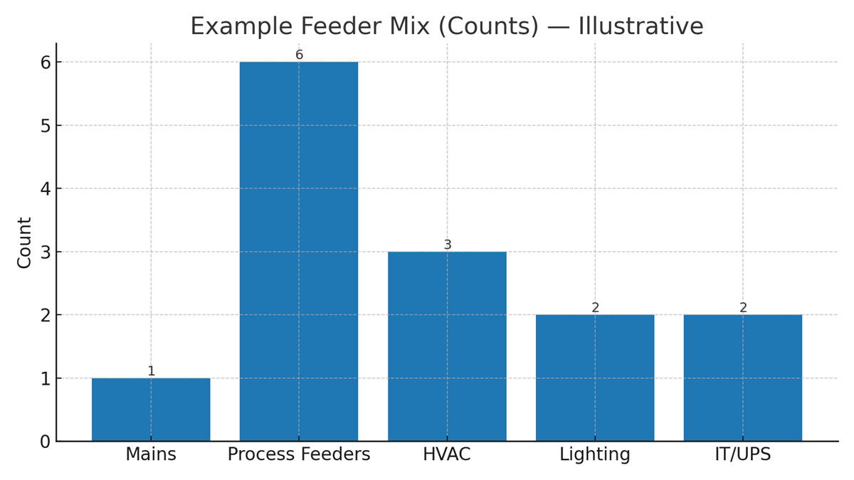
Illustrative Chart — Feeder Mix in an Industrial Switchboard (example)
UL 891 Requirements (U.S.)
UL 891 covers construction and performance criteria including short‑circuit withstand, temperature rise, dielectric strength, and routine production tests. Conductor bracing, creepage/clearance, and thermal limits are verified to ensure safe operation at the specified ratings.
Design & Test Essentials
- Short‑Circuit Withstand: Assembly bracing must survive the rated fault current for the specified duration.
• Temperature‑Rise: Conductors, terminations, and devices remain within allowable limits at rated current.
• Dielectric Tests: Insulation integrity confirmed after mechanical and thermal stresses.
• Production Tests: Routine verifications prior to shipment.
Enclosures & Environment
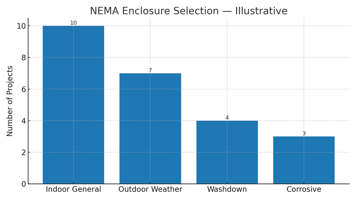
Select NEMA/IP ratings based on indoor/outdoor placement, washdown, dust, and corrosion exposure. Common choices include NEMA 1 (indoor), NEMA 3R (outdoor rainproof), and higher ratings where required.
Illustrative Chart — Common Enclosure Choices by Environment
NEC Article 408 Rules (U.S.)
- 408.3(A)(2): Barriers required at service equipment to isolate service bus/terminals.
• 408.4: Each circuit must be clearly identified; directories kept up‑to‑date.
• Working Clearances: NEC 110.26 applies (depth, width, height) for safe operation and maintenance.
• Markings: Display SCCR per NEC 110.24 and apply arc‑flash labels per NFPA 70E.
Switchboard vs Switchgear
| Feature | Switchboard (UL 891) | Low‑Voltage Switchgear (UL 1558) |
| Breakers | Fixed MCCB/ICCB | Draw‑out ACB/PCB |
| Compartments | Open chassis behind dead front | Fully compartmentalized |
| Short‑Time Withstand | Typically 3 cycles | Typically 30 cycles |
| Voltage | ≤ 600 V | 480 V–38 kV (LV to MV scopes differ) |
Panelboard vs Switchboard
| Feature | Panelboard (UL 67) | Switchboard (UL 891) |
| Mounting | Wall‑mounted | Freestanding |
| Ampacity | Up to ~1200 A | Up to ~6000 A |
| Depth | Typically 3–6 in | ≥ 18 in |
| Access | Front only | Front and/or rear |
MDB vs SDB Structure
- Main Distribution Board (MDB): Receives service power, feeds large loads and SDBs.
• Sub‑Distribution Board (SDB): Fed from MDB to serve areas/floors; improves selectivity and cable runs.
Sizing an Industrial Switchboard
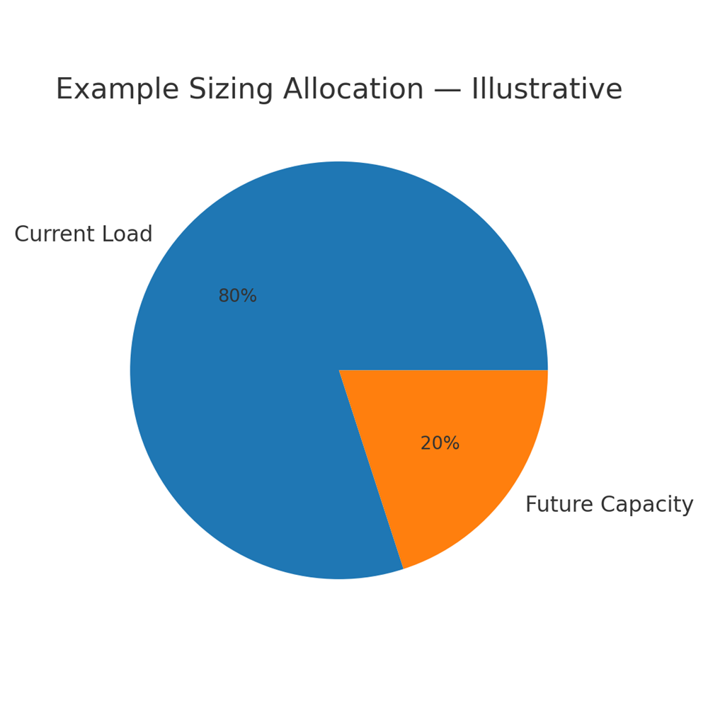
1) Calculate connected and demand loads. 2) Choose main device (breaker or main lugs) sized for continuous load × 125% where applicable. 3) Size busbars for current and temperature rise with acceptable margins. 4) Provide 20–30% spare capacity and space for future devices.
Illustrative Chart — Sizing Allocation (Current Load vs Future Capacity)
SCCR & AIC Ratings
- SCCR (Short‑Circuit Current Rating): Max fault current the assembly can safely withstand.
• AIC (Interrupting Rating): Max fault current a breaker can interrupt. Devices must have AIC ≥ available fault current at their terminals.
Coordinate with utility fault data and transformer impedance to select appropriate ratings; consider series ratings per code where allowed.
Coordination with Upstream
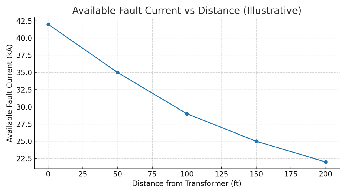
Obtain available fault current at the service from the utility. Use transformer kVA and %Z to estimate downstream levels. Ensure upstream devices don’t exceed assembly SCCR and that protective devices coordinate selectively where required.
Illustrative Chart — Available Fault Current vs Distance from Transformer
Arc‑Flash Safety & Labeling
Perform studies per NFPA 70E / IEEE 1584 to determine incident energy, boundaries, and PPE. Apply equipment labels, maintain working distances (often 18–36 in), and use safe work practices and training to minimize risk.
Selective Coordination & Healthcare Facilities
Emergency and legally required standby systems require selective coordination. Use time‑current curves so the closest device to a fault trips, preserving upstream continuity. Healthcare designs often require special attention to essential system branches.
Enclosure Rating: NEMA vs IP
| Environment | Common NEMA Types | Approx. IEC IP (reference) |
| Indoor, general | NEMA 1 | IP20–IP22 |
| Outdoor, rain | NEMA 3R | ≈ IP24 |
| Washdown | NEMA 4 | ≈ IP66 |
| Corrosive | NEMA 4X | ≈ IP66 + corrosion resistance |
Power Monitoring & Metering
Integrate revenue‑grade meters, energy metering CTs, and PQ analyzers to track consumption, power factor, and harmonics. Measurements support cost allocation, efficiency programs, and predictive maintenance analytics.
Grounding & Bonding
- Bond neutral to ground at the service only; isolate neutrals downstream.
• Size equipment grounding conductors per NEC 250.122 and grounding electrode conductors per NEC 250.66.
• Provide ground‑fault protection where required by code for services/feeders.
Installation & Commissioning
Pre‑energization checklist: verify torque on terminations, insulation resistance, device settings, labeling, clearances, and operation of interlocks. Capture as‑built documentation and update directories for all circuits.
Preventive Maintenance
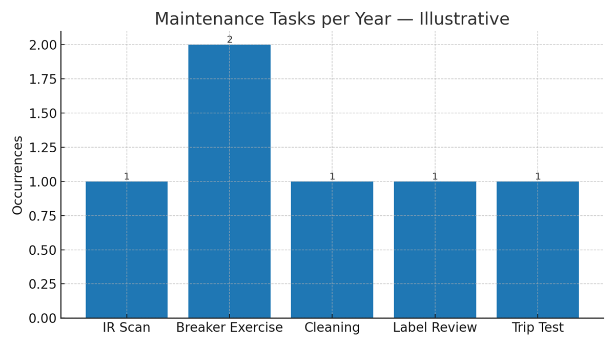
Adopt a program aligned with NFPA 70B: annual IR scans, cleaning, exercising breakers, verifying trip units, and re‑torque where needed. Update arc‑flash studies after significant changes or maintenance impacting protective device settings.
Illustrative Chart — Maintenance Tasks by Frequency (Annualized)
Procurement Specification (RFQ)
Include the one‑line diagram and load schedule; voltage, bus rating, SCCR, and device AIC; enclosure rating; device list and metering; test/certification requirements; and submittals (drawings, nameplate schedule, settings). Clear specifications prevent costly redesigns.
Real‑World Use Cases (U.S.)
- Hospitals: Redundant sources and selective coordination for essential systems.
• Data Centers: High SCCR, live metering of branch circuits, and maintenance access.
• Manufacturing: Modular sections for expansion and dedicated MCC integration.
FAQ: Industrial Switchboard
- What voltage does UL 891 cover? Up to 600 V AC/DC.
• How does UL 891 differ from UL 1558? UL 891 covers low‑voltage switchboards with open chassis; UL 1558 covers compartmentalized low‑voltage switchgear.
• What is SCCR vs AIC? SCCR is an assembly withstand rating; AIC is a device interrupting rating.
• Can a switchboard be used outdoors? Yes, select appropriate NEMA/IP enclosure.
• How do I size the main device? For continuous loads, apply 125% where applicable and verify AIC ≥ available fault current.


