


Busbar Bending Formulas: The Core Calculations Every Fabricator Needs
Every accurate busbar bend starts with a calculation, not a tool selection. Before specifying a CNC busbar bending machine, designing custom tooling, or running a first-article inspection, fabricators must work through four core busbar bending formulas: minimum bend radius, unfolding (developed) length, bend allowance, and bending force. Get these formulas right and the rest of the process — tooling, sequencing, QA — falls into place. Get them wrong and you’ll see cracks at the outer radius, dimensional drift, hole-position errors, and rework loops that destroy production margins.
This section walks through each busbar bending formula in plain terms, with worked examples for copper busbar bending calculations at common thicknesses.
Further exploration of Busbar Fabrication Machine can be found in the following recommended reading.
1. Minimum Bend Radius Formula (R = K × t)
The fundamental busbar bending formula defines the smallest radius you can safely bend a bar without cracking the outer fiber:
R_min = K × t
Where:
- R_min = minimum inner bend radius (mm)
- t = busbar thickness (mm)
- K = bending coefficient based on material and temper
K values for high-conductivity copper busbar:
| Busbar Thickness (t) | Coefficient K | R_min |
|---|---|---|
| Up to 10 mm | 1.0 | 1 × t |
| 11–25 mm | 1.5 | 1.5 × t |
| 26–50 mm | 2.0 | 2 × t |
Worked example: For a 12 mm thick copper busbar, R_min = 1.5 × 12 = 18 mm minimum inner radius. Bending tighter than 18 mm risks outer-fiber cracking, especially in half-hard or work-hardened copper.
For aluminum busbar, multiply K by approximately 1.2 because aluminum’s lower ductility-to-strength ratio demands a slightly larger radius at equivalent thickness.
2. Unfolding Length Formula (Developed Length Calculation)
The unfolding length formula calculates how long the flat busbar blank must be cut before bending so the finished part hits its target leg dimensions:
L = Σ(straight segments) + n × π × (R_inner + R_outer) / 2
Where:
- L = total developed (cut) length
- Σ(straight segments) = sum of all flat lengths between bends
- n = number of bends
- R_inner = inner bend radius
- R_outer = R_inner + t (outer bend radius)
Worked example: A copper busbar with two 90° bends, 100 mm straight segments (a, b, c), thickness 5 mm, inner radius 8 mm:
- Σ straight = 100 + 100 + 100 = 300 mm
- R_outer = 8 + 5 = 13 mm
- Curved contribution = 2 × π × (8 + 13)/2 = 2 × π × 10.5 ≈ 65.97 mm
- Total cut length L ≈ 366 mm
For 45° bevel angles, apply collinear correction — multiply the curved contribution by (angle/180) instead of using the full π factor.
3. Bend Allowance Formula
Bend allowance (BA) accounts for material stretch along the neutral axis when calculating cut length more precisely than the unfolding formula above:
BA = (π/180) × θ × (R + K_factor × t)
Where:
- θ = bend angle in degrees
- R = inner bend radius
- t = busbar thickness
- K_factor = neutral axis location (typically 0.33–0.5 for copper, depending on R/t ratio)
For tight bends (R/t < 2), use K_factor = 0.33. For looser bends (R/t > 4), use K_factor = 0.5. The bend allowance formula is more accurate than the simple π × (R_in + R_out)/2 method when tolerances are tight or when multiple bends compound across a single bar.
4. Bending Force / Pressure Formula
The bending force formula sizes the press or hydraulic machine for your worst-case busbar:
Pressure (MPa) = t × 1.5 to 2.5
Force (tons) ≈ pressure × bar width × safety factor
Worked example: Bending a 3 mm thick × 100 mm wide copper busbar:
- Pressure required ≈ 3 × 1.5 = 4.5 MPa minimum (up to 7.5 MPa for hard-temper)
- Required machine force ≈ 4.5–7.5 tons
Brass busbars (yield strength ~280 MPa) need less force than pure copper at the same thickness. Always size the bending machine for your hardest, thickest, and widest realistic job — not the easiest one.
What a Custom Busbar Bending Solution Includes: Beyond the Bending Formula
A robust custom busbar bending solution doesn’t stop at calculating the right bend radius — it extends to repeatability under real-world shop conditions, integrated workflows, and end-to-end traceability. The core elements of a complete solution include:
- The right bending platform (CNC or hydraulic) matched to your volume, geometry mix, busbar fabrication machine throughput, and team skill level.
- Custom tooling and fixtures designed for edgewise, offset, torsional, or layered bends specific to your part library.
- Angle control and springback compensation, ideally with encoder feedback on CNC systems and recorded springback factors per material/thickness combination.
- Surface-protection strategy — films, shims, polyurethane pads, and radiused clamps prevent clamp marks on conductive faces and visible surfaces.
- Inspection plan covering angle, radii, leg lengths, twist/flatness measurement, and cosmetics with documented gauge calibration.
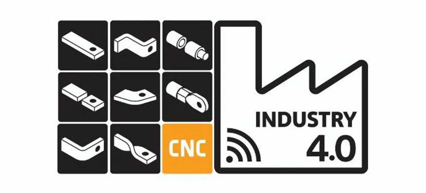
- Integrated punch-bend-mark workflow — modern busbar fabrication machines combine punching, countersinking, ID marking, and thread forming in a single flow, eliminating handling errors and improving throughput for custom bus bar fabrication runs.
For an overview of why integrated systems matter, see The Advantage of 3-in-1 Busbar Machines.
For an overview of why integrated systems matter, see The Advantage of 3-in-1 Busbar Machines.
Busbar Bending Types: Flat, Edgewise, Offset, U/Z, and Torsional Bends Explained
Every busbar bending formula applies differently depending on the bend type. Each geometry uses the same R = K × t and bend allowance equations, but the tooling, fixture orientation, and springback factor change with the axis of deformation. Here are the five primary bend types in custom busbar fabrication:
- Flatwise bends — Everyday L, U, and Z geometries where the bar bends in its thinnest dimension. The most common bend type and the easiest to calculate with standard formulas.
- Edgewise bends — The bending axis rotates 90° so the bar bends in its widest dimension. Used for taller bus sections or where panel layout demands the bar turn on its edge. Requires anti-twist support tooling.
- Offset bends — Two opposing bends create a step that lets the busbar clear obstacles while holding plane alignment. Apply the unfolding length formula twice (once per bend) when calculating the cut blank.
- U and Z bends — Two parallel or anti-parallel bends form U-shaped or Z-shaped routing. Both bends share a single cut-length calculation summing all straight segments and curved contributions.
- Torsional (twist) bends — The bar rotates about its longitudinal axis to align bolt pads with terminals oriented at different angles. Requires specialized torsion tooling and angle-index verification.
Advanced custom busbar fabrication shops also handle space bends (3D out-of-plane geometries) and combination bends (multiple bend types on a single bar). Both require springback compensation factors stored in CNC controller libraries when approaching tight angles.
Minimum Bend Radius for Copper Busbars: Validated Coefficients by Thickness
Your minimum bend radius (Rmin) is a core spec. It depends on thickness (t), temper (e.g., annealed vs half-hard), and die radius. A widely used reference for high-conductivity copper suggests:
- Up to 10 mm: Rmin ≈ 1×t
- 11–25 mm: Rmin ≈ 1.5×t
- 26–50 mm: Rmin ≈ 2×t
Always validate on your actual material and die set, especially near tight radii or cosmetic-critical surfaces. Formability is a trade-off against strength—cold-worked material (higher strength) tends to bend less easily—so Rmin is expressed as a multiple of thickness and “harder” tempers may require larger radii or localized annealing.For practical shop tips, see our new guide Bending Copper Busbar: How to Hit Minimum Radii, Avoid Marks, and Control Springback.
Springback and Angle Compensation in Busbar Bending Calculations
Springback occurs when the material elastically recovers after unloading. To hit nominal angles:
- Match die radius to your target Rmin (too small risks surface cracking; too large increases springback).
- Use encoder-based angle control with iterative compensation on first-article coupons.
- Record a springback factor in your program so subsequent parts repeat.
- For critical geometries, verify with radius gauges and an angle protractor or digital arm.
CNC vs Hydraulic Busbar Fabrication Machine: Including Novopress and Other Brand Comparisons
The choice of busbar fabrication machine drives every downstream cost and quality outcome in custom bus bar fabrication. Two architectures dominate the market, with established brand names anchoring each:
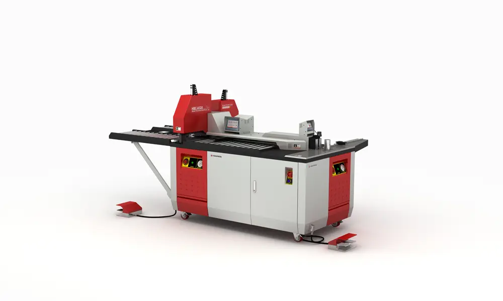
CNC busbar bending machines excel at repeatability, real-time angle feedback, and rapid changeover across many part numbers. They store springback factors, integrate marking and downstream operations, and are commonly deployed in automated cells for high-throughput switchgear and battery production. Brands frequently shortlisted include Novopress, Ehrt, Sahinler, Geka, and PAYAPRESS, each offering different control systems, encoder resolutions, and tooling libraries. The Novopress busbar bending machine range, for instance, focuses on portable and bench-mounted CNC units favored by panel-builders working on-site or in compact production cells.
Hydraulic bench machines and 3-in-1 systems combine cutting, punching, and bending in a single station — cost-effective for moderate volumes and broader shop tasks. Setup skill matters more than on CNC equipment; adding repeatable backgauges, stop systems, and tooling jigs closes most of the precision gap for typical electrical panel work.
When evaluating any busbar fabrication machine — whether a Novopress unit, a 3-in-1 hybrid, or a CNC press brake adapted for busbar work — focus on five specifications: encoder resolution, angle-measurement accuracy, tooling changeover time, controller DXF import support, and after-sales tooling availability.
Buying soon? Get realistic ranges and TCO guidance in Busbar Bending Machine Price (2025): Practical Guide and the broader Busbar Machine Price Guide.
Buying soon? Get realistic ranges and TCO guidance in Busbar Bending Machine Price (2025): Practical Guide and the broader Busbar Machine Price Guide.
Quality, Tolerances & Busbar Flatness Measurement After Bending
Surface condition and dimensional accuracy after bending directly affect electrical conductivity, mechanical fit, and assembly compliance. The four inspection categories every QA station should cover are angles and radii, leg lengths and offsets, surface cosmetics, and busbar flatness measurement across the bend zones.
Busbar flatness measurement standards and tools:
- Recommended flatness tolerance: ±0.05 mm per 1 m length for high-current applications.
- Width tolerance: ±0.2 mm for standard busbars.
- Measurement methods: Granite surface plate with dial indicator (lowest cost), coordinate measuring machine (CMM) for point-by-point verification, laser interferometry or 3D pattern-projection cameras for full-surface scanning, profilometry for high-precision research-grade verification.
- Repeatability target: ≤0.01 mm across 10+ measurements on the same part.
- Reference standards: ISO 1101 and ISO 12781 define geometric flatness tolerances; IEC 61439 and UL 508A provide assembly-level requirements.
Full inspection checklist for bent busbars:
| Inspection Item | Tool | Tolerance Target |
|---|---|---|
| Angle accuracy | Digital protractor or angle gauge | ±0.5° to ±1° |
| Inner bend radius | Radius gauge or template | ±0.5 mm |
| Leg lengths | Steel rule, calipers | ±0.5 mm |
| Offset height | Calipers, height gauge | ±0.3 mm |
| Twist (edgewise/torsional bends) | Surface plate + indicator | ≤0.5° per 100 mm |
| Flatness | Surface plate, CMM, or laser | ±0.05 mm/m |
| Surface marks | Visual + raking light | No visible clamp/die marks |
Surface protection during bending: Use polyurethane films, mark-free pads, shims, and radiused clamps to prevent marking on visible or bolted faces. Deburr edges before clamping to avoid drag scratches. For stacked or complex bend sequences, full-scale paper templates or 1:1 plotted CAD drawings reduce compounding errors across multiple bends.
Standards Context for Custom Bus Bar Fabrication: IEC 61439 and UL 508A
Even a perfect bend must live inside an assembly standard. IEC 61439-1 (2020) defines the general rules and verification framework for low-voltage switchgear/controlgear assemblies—your finished bar must meet the assembly’s construction and verification requirements.In North America, UL 508A includes guidance on supporting live parts (e.g., busbar standoffs, insulating barriers) and component acceptance; ensure your supports/barriers remain compliant after adding offsets/layers.
If your projects involve UL switchboards, you may also find our explainer useful: Industrial Switchboard (UL 891) — Plain-English Guide for Engineers.
Custom Busbar Bending Planner: Geometry-by-Geometry Reference Table
| Geometry / Feature | Typical benefit | Best for (material/size) | Throughput impact | Repeatability focus | Tooling / fixture note | Validation / inspection note |
|---|---|---|---|---|---|---|
| Flatwise bends | Standard L/U/Z parts | Cu/Al up to shop capacity | High | Angle control, springback | Match die radius to spec | Check angle on first-articles; log springback factor |
| Edgewise bends | Narrow width, tall section | Stiff bars that risk twist | Medium | Back-gauge alignment | Edge support & anti-twist | Verify parallelism/planarity after bend |
| Offset bends | Clearance over obstacles | Panel layout constraints | Medium | Stop accuracy | Dedicated offset tooling | Measure offset height and leg lengths |
| Torsional (twist) bends | Rotational alignment of pads | Terminal orientation needs | Low–Medium | Angular index accuracy | Torsion tool with stops | Confirm twist angle with template |
| Layer/space bending | Multi-layer stacks | Compact switchgear | Medium | Stack squareness | Pressure plates/packers | Inspect stack gaps & mark-free surfaces |
| Tight radii (near Rmin) | Compact routing | Thin/annealed Cu preferred | Medium | Surface marking risk | Larger die radius; films/shims | Visual + radius gauge; consider NDT if critical |
| Integrated punch→bend flow | Fewer setups, ID traceability | Repetitive parts libraries | High | Tool path + program control | Shared datum strategy | First-piece FAIR; record CP/CPK where needed |
Notes: “Throughput” and “Repeatability” are qualitative. For high-conductivity copper, indicative Rmin: up to 10 mm ≈ 1×t, 11–25 mm ≈ 1.5×t, 26–50 mm ≈ 2×t—validate on your material and dies.
RFQ Checklist for a Custom Busbar Bending and Fabrication Solution
- Material & temper: Copper/Aluminum; grade; half-hard/annealed.
- Bar size range: Thickness × width; max length.
- Bend types: Flat / Edgewise / Offset (height) / U / Z / Torsional (angle).
- Radii & angles: Target Rmin; ± angle tolerance; leg lengths.
- Sequence: Punch-then-bend, or bend-then-punch; datum strategy.
- Surface protection: Films/shims; mark-free faces.
- Inspection: First-article plan; gauges; documentation.
- Throughput: Parts/hour; mix (no. of SKUs/shift).
- Integration: Marking, countersink/thread forming, measurement.
- Compliance context: IEC 61439-1 / UL 508A; supports/barriers.