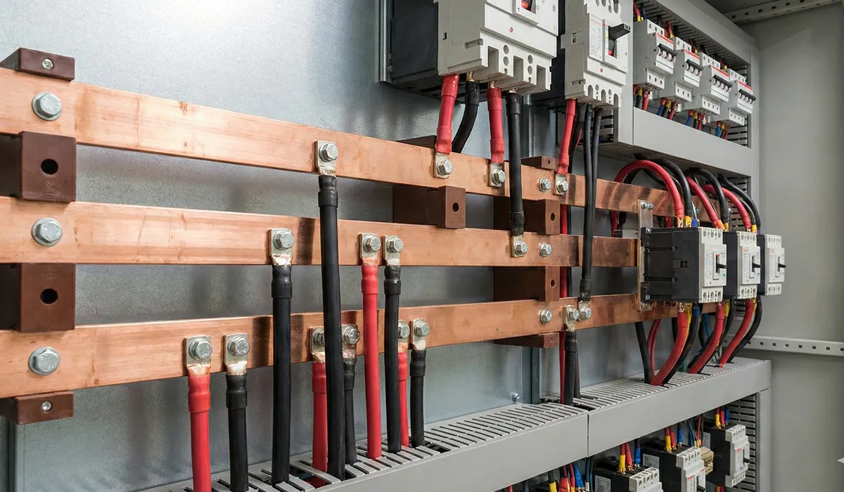


What is a switchboard busbar (and how it works)
A busbar is a metallic bar or strip—typically copper or aluminum—mounted inside switchgear and switchboards to distribute high currents throughout a power distribution assembly. In modern electrical systems, the busbar material, cross-section, and busbar layout are engineered together: flat profiles maximize surface area for cooling and make joints easier to bolt and plate. Depending on construction, bars may be bare or insulated (e.g., heat-shrink sleeve or epoxy coating), and they’re supported on insulators with defined creepage and clearance distances. Understanding busbar meaning in the context of switchboard design goes beyond the conductor itself—it encompasses busbar configuration, busbar specifications, spacing references, and the full busbar wiring system inside the enclosure.
If you are looking for more information about Busbar Fabrication Machine , it is recommended not to miss reading this article.
Switchboard busbar vs. busbar trunking (IEC 61439-6)
“Power busbar” can mean different things depending on the context. Internal switchboard busbars—sometimes called the main busbar or main bus bar of an assembly—are part of a switchgear busbar system verified to IEC 61439-1/-2 (global) or UL 891 (North America). By contrast, busbar trunking systems (busways) are separate enclosed products used to distribute power around a facility and are verified to IEC 61439-6. Switchgear bus bars designed as internal components operate under different design rules than external busbar trunking, so it is essential to reference both regimes when specifying a switchboard that connects to a busway: the switchboard for its internal busbars, and the busway for external distribution.
For projects subject to IS/IEC 61439 or EN 61439-1, confirm which parts of the standard apply to your assembly type. Switchboard busbars inside main distribution boards (MDB) fall under IEC 61439-2; busbar trunking products fall under IEC 61439-6.
For a comprehensive understanding of Busbar bending techniques (design & quality), we highly recommend reviewing this article.
Busbar material: Copper C110 vs. Aluminum 6101 (ASTM-based comparison)
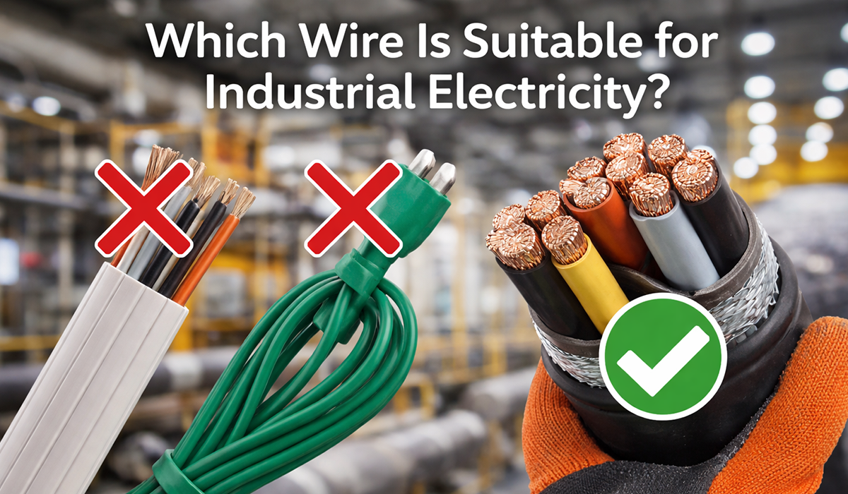
Busbar material selection directly affects size, weight, joints, and total cost of ownership. Use standard designations so suppliers quote apples-to-apples and your documentation remains fully auditable. Bus bar material choice is one of the first decisions in any busbar design guide.
- Copper busbar — Cu C110 (ASTM B187): Benchmark conductivity (~100% IACS), excellent joints, higher density. The copper busbar is the standard choice in high-current switchgear busbars and MDB applications where space is constrained. For the full comparison, see: Copper vs. Aluminum Busbar.
- Aluminum busbar — Al 6101 (ASTM B317): Lower mass and price; requires a larger cross-section for the same ampacity and careful joint design including surface preparation, suitable plating, and controlled contact pressure. Aluminum is common in commercial distribution boards where weight and cost are primary drivers.
When joints matter—and in any live busbar application they always do—specify plating at interfaces: tin plating is common across most busbar systems; silver plating is reserved for demanding, high-cycle, or high-temperature joints. Copper busbar marking at joints and connection points supports field inspection after installation and thermal cycling.
Clearance & creepage in switchboard busbar design (IEC 60664-1, UL 891)
Two distances govern insulation coordination in any busbar design guide for switchboards and switchgear:
- Clearance: the shortest air distance between live busbar sections or between live parts and earth (prevents flashover under transient overvoltage).
- Creepage: the distance along an insulating surface between conductors (prevents surface tracking under contamination).
Minimum values depend on the insulation system, pollution degree, and overvoltage category. In IEC markets, use IEC 60664-1 tables for busbar spacing reference; in North America, UL 891 and NEC Article 408 govern internal switchboard construction and installation details. Engineering specifications must clearly document which table references were applied, particularly for insulated busbar designs where the coating modifies effective clearance.
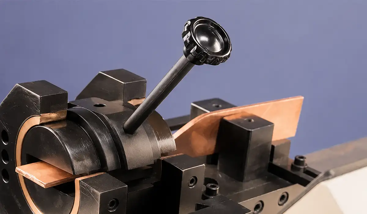
A PAYAPRESS copper busbar machine is a practical solution for producing accurate switchboard busbars that meet the demands of modern electrical distribution systems. Since switchboard busbars must maintain proper clearance, creepage, current capacity, joint quality, and short-circuit strength, precise cutting, punching, and bending are essential during fabrication. By using a copper busbar machine by PAYAPRESS, panel builders and switchboard manufacturers can improve production accuracy, reduce manual errors, and achieve consistent copper busbar processing for IEC- or UL-based switchboard assemblies.
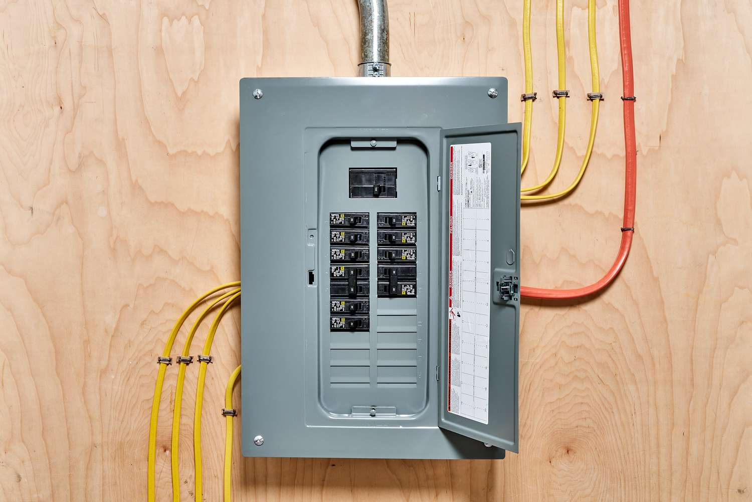
Temperature-rise verification under IEC 61439-1/-2
IEC 61439 modernized type testing into design verification with three permitted methods: test, comparison, or assessment. Temperature-rise limits ensure that busbars, devices, and connections within the busbar panel do not exceed allowable over-temperatures under rated continuous load. Standard busbar ratings at high current levels typically demand physical testing; assemblies at lower ratings may qualify by comparison or assessment within strict rules. Document ambient assumptions, the verification method applied, and all test results. For continuous busbar design at elevated ratings, the thermal performance of the busbar section, its supports, and adjacent devices must all be confirmed together.
Learn more: ABB workbook: IEC 61439 in practice .
Specifying a switchboard busbar: rating, bracing, plating, insulation
Use this framework—effectively a busbar design guide for RFQs—when writing your busbar specifications or issuing an inquiry to suppliers. Each item below maps directly to a design decision that affects busbar calculation, busbar installation engineering standards, and long-term reliability.
- Rated current and duty (continuous, diversity factor) with the required verification method (IEC: test/comparison/assessment, or UL compliance basis). State whether the busbar panel must carry full continuous load or a derated duty cycle.
- SCCR / AIC target and the available fault current at the installation. Available fault current drives busbar supports, bus bar bracing, and bus bracing hardware selection. Inadequate bracing is one of the most common field failures in switchgear bus bar installations.
- Busbar material & standard: Cu C110 (ASTM B187) or Al 6101 (ASTM B317); specify required plating (tin or silver) at all joint interfaces. For fabrication insights, see our production pages: Busbar Bending Machine, Busbar Punching & Cutting Machine, and 3-in-1 busbar Machine.
- Busbar arrangement: single, double, or laminated (sandwich / interleaved busbar) for compactness and lower inductance. The busbar layout inside the switchboard enclosure affects both thermal performance and the creepage/clearance achievable with a given busbar configuration.
- Insulation: bare, heat-shrink, or epoxy-coated insulated bars. State clearly in busbar specifications whether the busbar in switchboard is insulated and specify the creepage/clearance table references applied.
- Assembly & torque: specify the electrical busbar bolt material and follow the device OEM torque tables. Require inspection marks after thermal cycling. Include busbar drawings in the required documentation package so field teams can verify how to inspect busbar dimensions after installation.
- Compliance regime: IEC 61439-1/-2 / IS/IEC 61439 / EN 61439-1 (EU and international) or UL 891 + NEC Article 408 (North America). State this prominently in the engineering specifications and RFQ.
Further exploration of busbar arrangements can be found in the following recommended reading.
When to choose laminated (interleaved busbar) designs
Laminated and interleaved busbar configurations reduce loop inductance and improve thermal performance in compact, high-current, high-harmonic environments—particularly in MDB busbar sections with significant non-linear load content. A DC busbar system design for UPS or rectifier applications may also benefit from laminated geometry. Laminated busbars cost more and require careful interface hardware selection, but they excel where footprint, EMI, and busbar spots design precision all matter simultaneously.
Tapping policy and safe connections to live busbars (NEC/UL)
Uncontrolled tapping of a live busbar is hazardous and typically outside the product’s listing. In North America, follow UL 891 construction rules and NEC Article 408 installation practices: use listed hardware, lugs, or tap-off provisions specifically intended for the bus. All tap-off points should be reflected in the busbar drawings and verified against the busbar installation engineering standards applicable to the project.
High-utility busbar selection matrix
The matrix below helps engineers finalize busbar material, busbar arrangement, plating and insulation, and verification approach for common switchboard busbar use cases. Use it during pre-RFQ reviews to align stakeholders on busbar system design choices before issuing enquiries to busbar machinery suppliers or switchgear OEM partners.
| Use case | Rated current band (A) | Busbar material | Arrangement | Insulation | Plating | Short-circuit target (kA RMS 1s) | Spacing reference | Verification method | Notes |
|---|---|---|---|---|---|---|---|---|---|
| Main LV switchboard / switchgear busbar (industrial) | 1600–4000 | Cu C110 (ASTM B187) or Al 6101 (ASTM B317) | Single or double stack | Bare or heat-shrink | Tin common; silver at joints | 50–100 | IEC 60664-1 or UL 891 |
IEC 61439 test/comparison | Select busbar material by conductivity vs. mass trade-off; confirm bus bar bracing and busbar section supports for available fault current. |
| MDB busbar with high harmonic content | 2500–6300 | Cu C110 (copper busbar preferred) | Double or laminated (interleaved busbar) | Heat-shrink or epoxy | Tin/silver | 65–100 | As above | Test preferred at high currents | Laminated busbars lower stray inductance and temperature rise; busbar system design must account for harmonic derating. |
| Commercial distribution board (internal switchboard) | 800–1600 | Cu or Al 6101 | Single | Bare or heat-shrink | Tin | 25–50 | As above | Assessment/comparison possible ≤1600 A | Verify ambient; derate busbar if >40 °C. Best switchboard instruments for factories and commercial buildings require verified busbar ratings. |
| Busbar trunking interface / busbar section at switchgear bus | 1000–4000 | Per BTS | Per BTS | Per BTS | Per BTS | Per BTS | IEC 61439-6 | As per BTS | Clarify interface hardware and tap-off ratings with the busway vendor; reference IS/IEC 61439 or EN 61439-1 as applicable. |
Notes & assumptions: Current bands and kA targets are typical planning categories to drive verification and procurement conversations; final values must be confirmed by design/testing per IEC 61439-1/-2 or UL 891 and project-specific fault studies. Busbar material standards for RFQs: ASTM B187 (copper C110) and ASTM B317 (aluminum 6101). Sources: ABB (2016), nVent Hoffman guide; IEC 60664-1 (2020); UL 891 program page (ongoing). All values are indicative and subject to change.
Price and TCO factors for busbar systems
- Busbar material & plating: Cu vs. Al; tin vs. silver joints. Use commodity-indexed quotes and specify Incoterms. See busbar material comparison for a full cost and conductivity analysis.
- Verification & testing: Type tests or third-party evidence add upfront cost but significantly de-risk compliance with IEC 61439 design verification and UL 891 requirements. Leading precision copper bus bar manufacturers for switchgear OEMs typically maintain third-party type test evidence across a range of standard busbar ratings.
- Environment: Elevated ambient temperature or corrosive atmospheres may drive insulation, plating, and derating decisions—directly impacting lifetime costs of the busbar wiring system.
- Integration: Interfaces to busbar trunking (IEC 61439-6), metering, and power monitoring equipment add system cost but improve overall visibility and control of the busbar panel.
- Busbar machinery: In-house busbar design and fabrication using dedicated busbar machinery—punching, cutting, bending—can reduce lead times and improve dimensional consistency of busbar drawings versus outsourced supply.
RFQ checklist for switchboard busbar projects
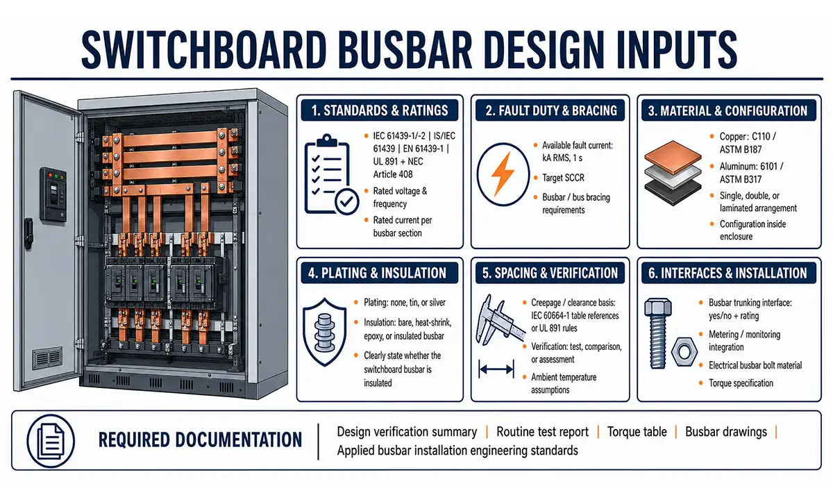
- Standards regime: IEC 61439-1/-2, IS/IEC 61439, EN 61439-1, or UL 891 + NEC Article 408
- Rated voltage and frequency; rated current per busbar section
- Available fault current (kA RMS, 1s), target SCCR, and bus bar bracing / bus bracing requirements
- Busbar material and standard (C110/ASTM B187 or 6101/ASTM B317), busbar arrangement (single/double/laminated), and busbar configuration inside the enclosure
- Plating (none/tin/silver) and insulation type (bare/heat-shrink/epoxy/insulated busbar): state clearly whether the busbar in switchboard is insulated
- Busbar spacing reference and creepage/clearance basis (IEC 60664-1 table references or UL 891 rules)
- Verification method (test/comparison/assessment) and ambient temperature assumptions for busbar calculation
- Interface to busbar trunking (yes/no; rating) and metering/monitoring integration
- Electrical busbar bolt material and torque specification
- Required documentation: design verification summary, routine test report, torque table, busbar drawings, and busbar installation engineering standards applied
Summary: Switchboard busbars are simple in appearance but governed by exacting standards. Lead with the applicable regime (IEC or UL), select busbar material and busbar arrangement for your current and fault duties, lock in busbar spacing and temperature-rise verification early, and confirm bus bar bracing against available fault current. Use the selection matrix and RFQ checklist above to brief suppliers and avoid redesigns later. Whether you are working on a single busbar switchgear panel or a multi-section MDB busbar assembly, the principles of busbar design—material, configuration, insulation, and verification—remain constant.