


For your convenience, if you prefer listening, you can listen to the rest of this article via the audio file below.
What Is Wiring Duct? Meaning, Purpose, and Use in Control Panels
Wiring Duct is an extruded channel, usually made from PVC (polyvinyl chloride), nylon, or halogen-free plastic, that carries electrical wires inside an enclosure. Most versions use a base channel with a wire duct with cover, while some designs use hinged covers or open-top formats. In a control panel, the duct does not replace circuit protection or insulation. Instead, it acts as a cable containment system that holds wiring in planned routes and prevents uncontrolled wire movement near terminals, DIN rail devices, relays, drives, and PLC modules.
Before taking a closer look at duct cutters and their key advantages, we recommend checking out one of the best wiring duct cutters available on the market.
A panel builder uses duct to separate circuits by function. For example, 24 VDC control wiring, analog signal wiring, motor control wiring, and 230/400 VAC power wiring should follow different paths when the panel design allows it. This separation improves electrical panel organization and reduces noise transfer, especially when low-level signal circuits run near contactors, VFDs, or power supplies. Therefore, good duct layout supports both neat assembly and stable machine operation.
Professional wire management inside enclosures also reduces maintenance time. When technicians open a cabinet, clear routing helps them trace conductors without pulling wire bundles apart. Moreover, duct covers protect insulation from abrasion and keep loose conductors away from moving parts, sharp panel edges, or hot components. Standards such as UL 508A for industrial control panels and IEC 61439 for low-voltage switchgear assemblies do not make neatness optional in practice; they push panel builders toward safe spacing, protected wiring, and repeatable workmanship. For a comprehensive understanding of cable management principles.
| Feature | Description |
|---|---|
| Primary Function | Route and protect wiring inside control panels |
| Common Materials | PVC, nylon PA6, halogen-free thermoplastics |
| Cover Type | Snap-on, hinged, flush, or open-top |
| Standard Context | UL 508A, IEC 61439, EN 50085 family references |
| Typical Environments | Control panels, MCCs, automation enclosures, switchboards |
Wiring Duct Types Explained: Solid Wall, Narrow Slot, and Wide Slot
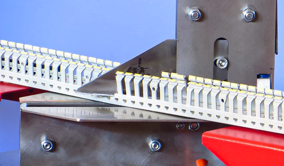
Wiring duct types differ mainly by sidewall design. Solid wall wiring duct has closed sides, narrow slot duct uses many small finger openings, and wide slot duct uses larger openings for heavier bundles. Consequently, the right type depends on routing flexibility, wire diameter, appearance, enclosure density, and the need for future changes. In most panel shops, slotted duct becomes the daily default, while solid wall and specialty profiles solve specific layout or protection problems.
Further exploration of What Is Narrow Slot Wiring Duct? can be found in the following recommended reading.
Solid Wall Wiring Duct — Maximum Protection for Clean Installations
Solid wall wiring duct uses closed sidewalls with no slots along the run. It gives the panel a clean, continuous appearance and keeps dust, debris, and stray wire ends away from the duct interior. This makes it useful for customer-facing cabinets, clean installations, and sensitive signal routing where the designer wants stronger physical separation than a finger duct can offer. However, the installer must plan exits carefully, because wires cannot leave through side slots at arbitrary points.
The main limitation comes from that same closed design. If a technician needs to add a wire later, they may need to remove covers, drill exits, or reroute a longer path. Therefore, solid duct works best when the layout has stable terminal positions and low future rewiring risk. In contrast, slotted duct suits panels that may change during commissioning or after machine upgrades.
Further exploration of Slotted vs Solid Wiring Duct can be found in the following recommended reading.
Narrow Slot Wiring Duct — The Standard Choice for Most Control Panels
Narrow slot wiring duct uses closely spaced fingers that let wires exit along the side while still keeping bundles contained. It is the standard choice for wiring duct for control panels because it balances appearance, flexibility, and wire retention. The narrow slot pattern supports individual control wires, small groups, and terminal-level branching without forcing the installer to cut special openings.
This design also helps during commissioning. If a wire lands on a different terminal than expected, the technician can exit one slot earlier or later without rebuilding the route. As a result, narrow slot duct reduces rework compared with solid wall channel. However, it offers less physical enclosure than solid duct, so designers should still separate sensitive signal circuits from noisy power runs.
Wide Slot Wiring Duct — High-Density Wiring and Easy Routing
Wide slot duct uses larger finger openings, so thicker cables and grouped wire bundles can leave the channel without tight bending. This makes it useful in high-density wiring duct layouts, motor control panels, and large automation cabinets where several conductors must exit together. It also helps when larger wire gauges need more bend space near terminals.
The trade-off is visual openness. Wide slots expose more of the wire bundle and provide less fine retention than narrow slot duct. Therefore, panel builders often use it near contactors, soft starters, VFDs, and larger terminal blocks, while using narrow slot duct around PLC I/O and smaller control devices. This mixed approach keeps the cabinet practical without sacrificing order.
For a comprehensive understanding of Benefits Wiring Duct Cutter, we highly recommend reviewing this article.
| Duct Type | Slot Style | Best For | Wire Exit Flexibility | Appearance |
|---|---|---|---|---|
| Solid Wall | No slots | Signal-sensitive or clean installations | Low | Very clean |
| Narrow Slot | Small slots | General control panel wiring | High | Clean |
| Wide Slot | Large slots | High-density or larger wire gauges | Very high | More open |
Wiring Duct Sizes: How to Choose Width and Depth for a Control Panel
Wiring duct sizes depend on two basic dimensions: width and depth. Width controls how many conductors can sit side by side, while depth affects bundle height and cover closure. Therefore, wiring duct width and depth selection should start with the expected conductor count, wire diameter, routing path, bend radius, and future expansion margin. The practical question is simple: what size wiring duct do I need for a control panel without overfilling it?
Understanding Wire Fill Ratio in Wiring Duct
Wire fill ratio means the percentage of the duct’s usable cross-sectional area occupied by wires. Panel builders commonly keep duct fill around 50–60%, because full ducts create cover closure problems, increase heat concentration, and leave no room for later additions. For a conservative calculation, multiply duct width by depth, adjust for wall thickness, then compare that usable area with the total area of all wires. The National Electrical Code fill rating guidelines offer a useful reference point for understanding maximum conductor fill in enclosed raceways.
To estimate wire area, use the conductor outside diameter, not only copper size. The simple circular-area method is π × radius², or 0.785 × diameter². Then multiply that value by the number of similar wires. For mixed sizes, calculate each group separately and add the results. This method helps answer how to calculate wire fill for wiring duct before the panel builder commits to drilling and mounting.
Common Wiring Duct Sizes and When to Use Each
Common metric sizes range from small 25 × 40 mm duct to large 100 × 100 mm cabinet duct. Small channels suit sensor wiring, door wiring, and compact terminal rows. Medium sizes such as 40 × 60 mm and 60 × 60 mm fit many general control panels. However, MCCs, drive panels, and high-density automation panels often need 80 × 80 mm or 100 × 100 mm duct to maintain cover closure and service space.
| Width × Depth | Typical Wire Fill | Best Application |
|---|---|---|
| 25 × 40 mm | Low | Small panels, signal wiring, door wiring |
| 40 × 60 mm | Medium | General control panels and PLC cabinets |
| 60 × 60 mm | Medium–High | Multi-zone panels and mixed control wiring |
| 80 × 80 mm | High | MCC sections and larger automation panels |
| 100 × 100 mm | Very high | High-density industrial panels and main wireways |
For a wiring duct width selection guide for panel builders, start with the known wire schedule, then add at least 20–30% practical growth allowance. Next, check component spacing and terminal access. A larger duct that blocks terminal screws or device labels can slow maintenance, even if its wire capacity looks correct on paper.
Slotted vs Solid Wiring Duct: Which Type Is Better for Your Panel?
Slotted vs solid wiring duct which is better depends on the panel’s routing complexity. For most industrial control panels, slotted wiring duct is the better default because it gives faster installation, easier wire exits, and simpler future changes. Solid wall duct becomes the better choice when appearance, containment, or signal protection matters more than routing flexibility.
| Criterion | Slotted Duct | Solid Wall Duct |
|---|---|---|
| Wire exit flexibility | High | Low |
| EMI/RFI separation support | Low–Medium | Medium |
| Installation speed | Fast | Medium |
| Appearance | Standard industrial | Premium clean |
| Maintenance access | Easy | Moderate |
| Best for | General control wiring | Sensitive signal wiring or clean layouts |
For power circuits, slotted duct helps installers branch into contactors, breakers, and terminal blocks without special cutouts. For low-level analog, encoder, or communication wiring, solid wall duct can add useful physical discipline when paired with proper separation and shielding practice. However, duct material alone does not replace screened cable, bonding, spacing, or EMC design.
The direct recommendation is clear. Use slotted duct for most panel wiring, especially where changes may occur during commissioning. Use solid wall duct for stable signal routes, display-grade cabinets, or installations where the customer expects a very clean internal finish. In many panels, the best answer combines both types rather than forcing one duct style everywhere.
Wiring Duct in Control Panels: Applications and Basic Layout Best Practices
Wiring duct applications in industrial automation panels begin before component mounting. The layout drawing should define duct routes, DIN rail positions, terminal zones, clearance around devices, and service access. If the duct path comes too late, the assembler may force wires through poor routes, cover terminal labels, or create tight bends near devices. Therefore, duct planning belongs in the mechanical layout phase, not at the end of wiring.
Power and control conductors should not share every route by default. High-current motor wiring, VFD output cables, and mains conductors can introduce heat and electrical noise. Therefore, separate duct channels help protect signal quality and reduce troubleshooting time. Corner pieces, reducers, duct filler, wire retainers, dividers, and wiring duct accessories also improve panel layout wiring when wire paths change size or direction.
- Plan duct routing on the panel layout drawing before drilling.
- Maintain at least 25 mm clearance between duct edge and component terminals.
- Separate 24 VDC control wiring from 230/400 VAC power wiring with dedicated duct runs.
- Use horizontal duct at top and bottom, with vertical duct along both sides.
- Keep wire fill below about 60% to allow cover closure and future additions.
- Label duct sections during installation to simplify future maintenance.
How to Cut Wiring Duct
How to cut wiring duct depends on volume, required finish, available tools, and duct material. Cut quality matters because cracked PVC, uneven ends, and burrs create safety, appearance, and assembly problems. Clean edges help covers seat correctly and reduces the risk of insulation damage. Therefore, panel shops should treat duct cutting as a controlled production step, not as rough plastic trimming.
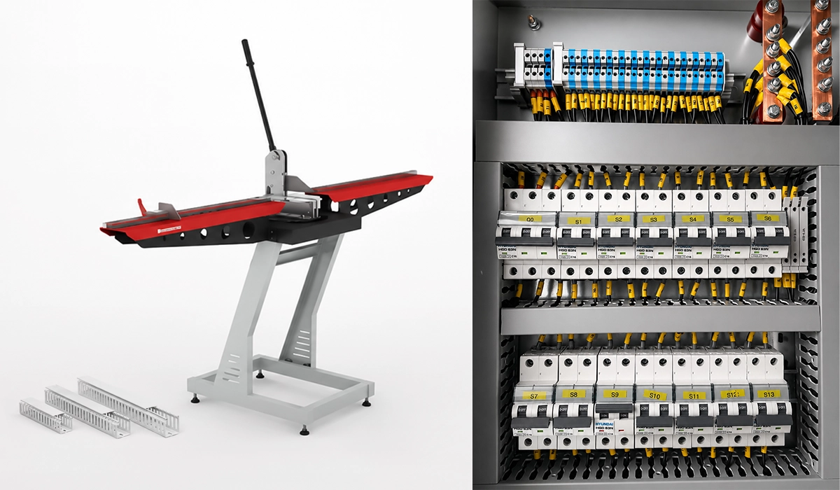
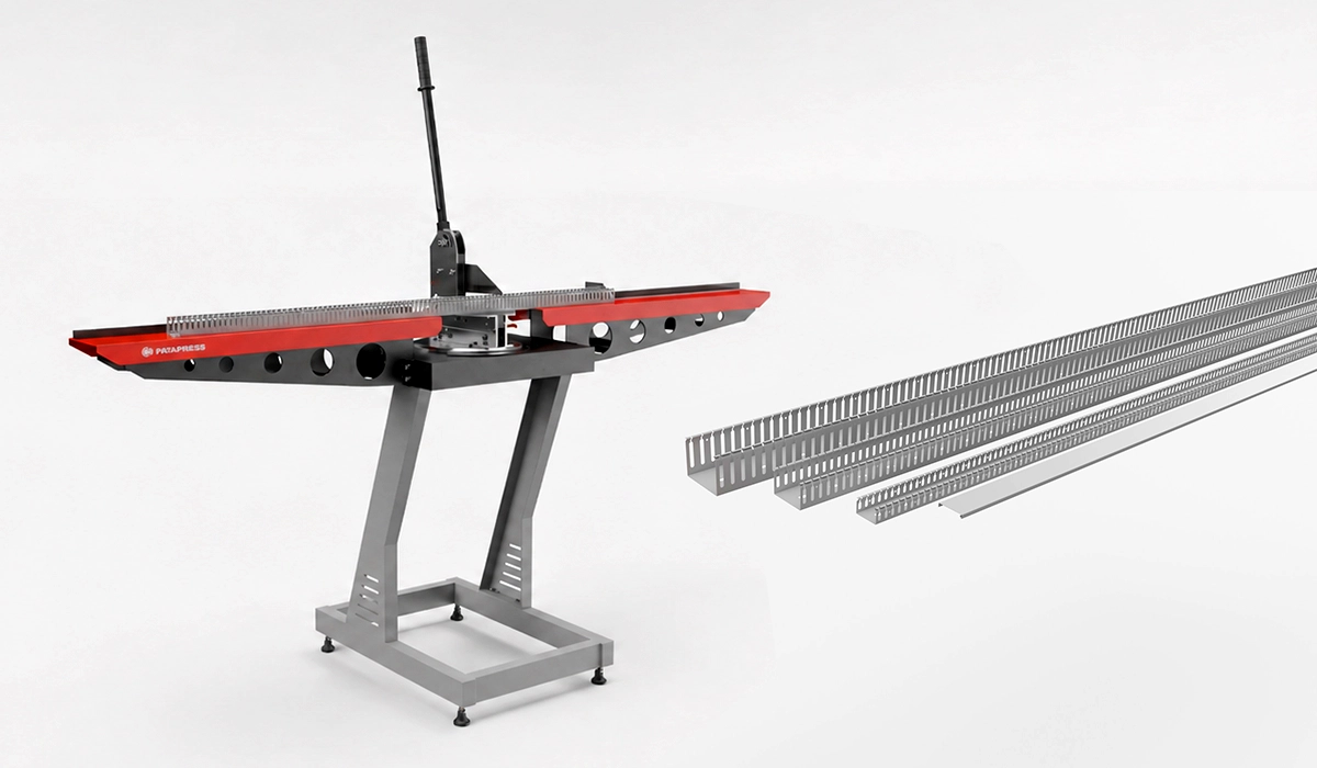
Using a Dedicated Wiring Duct Cutter
A dedicated wiring duct cutter uses a shear or guillotine action to cut the duct squarely with controlled force. This is the preferred method for panel shops because it reduces cracking, improves length repeatability, and produces a cleaner end than a utility knife. A bench tool with a measurement scale and stop block also helps operators cut repeated lengths without marking every piece.
This method directly answers how to cut wiring duct without cracking. The blade supports the plastic during the cut, and the operator applies force through a guided mechanism. As a result, PVC cable duct material properties allow the profile to hold its shape better than it does under twisting or sawing pressure. For daily production, this method gives the best combination of speed, safety, and finish quality.
Cutting Wiring Duct with a Handsaw or Utility Knife
A fine-tooth handsaw can cut duct acceptably when the job volume is low or the installer works in the field. The operator should support the duct fully, mark a square line, and use a straight-edge guide or miter box. After cutting, they should deburr the edge so the cover snaps on cleanly and wires do not contact sharp plastic.
A utility knife works only for thin-wall duct or light trimming. It can score PVC, but it often produces uneven edges if the operator tries to cut through too quickly. Therefore, wiring duct cutter vs utility knife which is better has a practical answer: use a cutter for professional volume, and reserve the knife for small corrections only.
Cutting Wiring Duct with a Miter Saw or Table Saw
A miter saw or table saw can produce accurate cuts in a workshop when the operator uses the correct blade and supports the duct properly. A fine-tooth blade helps reduce chipping, while controlled feed speed limits heat buildup and melting. For repeat production, a stop block gives consistent lengths and reduces measuring errors.
However, powered saws need stronger safety controls than a hand cutter. The operator should clamp or fixture the duct, control offcuts, and avoid forcing the plastic into the blade. This method works well for high-volume pre-cut duct, but it can create dust and noise. Therefore, many panel shops still prefer a dedicated guillotine-style cutter for standard plastic duct work.
| Cutting Method | Cut Quality | Speed | Best For | Risk of Cracking |
|---|---|---|---|---|
| Dedicated duct cutter | Excellent | Fast | Professional panel shops | Very low |
| Fine-tooth handsaw | Good | Medium | Field work and low volume | Low–Medium |
| Utility knife | Fair | Slow | Thin-wall duct only | Medium |
| Miter or table saw | Excellent | Fast | High-volume workshop cutting | Low with correct blade |
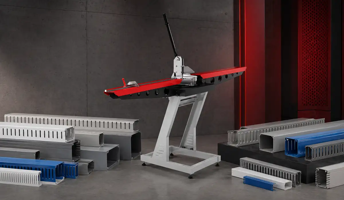
Wiring Duct Cutter: Benefits, Features, and What to Look for Before Buying
A wiring duct cutter is a worthwhile investment when a panel shop cuts duct every week or every day. The best wiring duct cutter for clean cuts reduces rework, improves edge quality, and helps operators repeat dimensions accurately. It also protects the duct profile, so snap-on duct cover sections close more reliably after cutting. For production teams, the time saved across dozens of cuts quickly exceeds the cost of the tool. For a comprehensive understanding of structured wiring systems and enclosure design, we highly recommend reviewing this article on structured cabling.
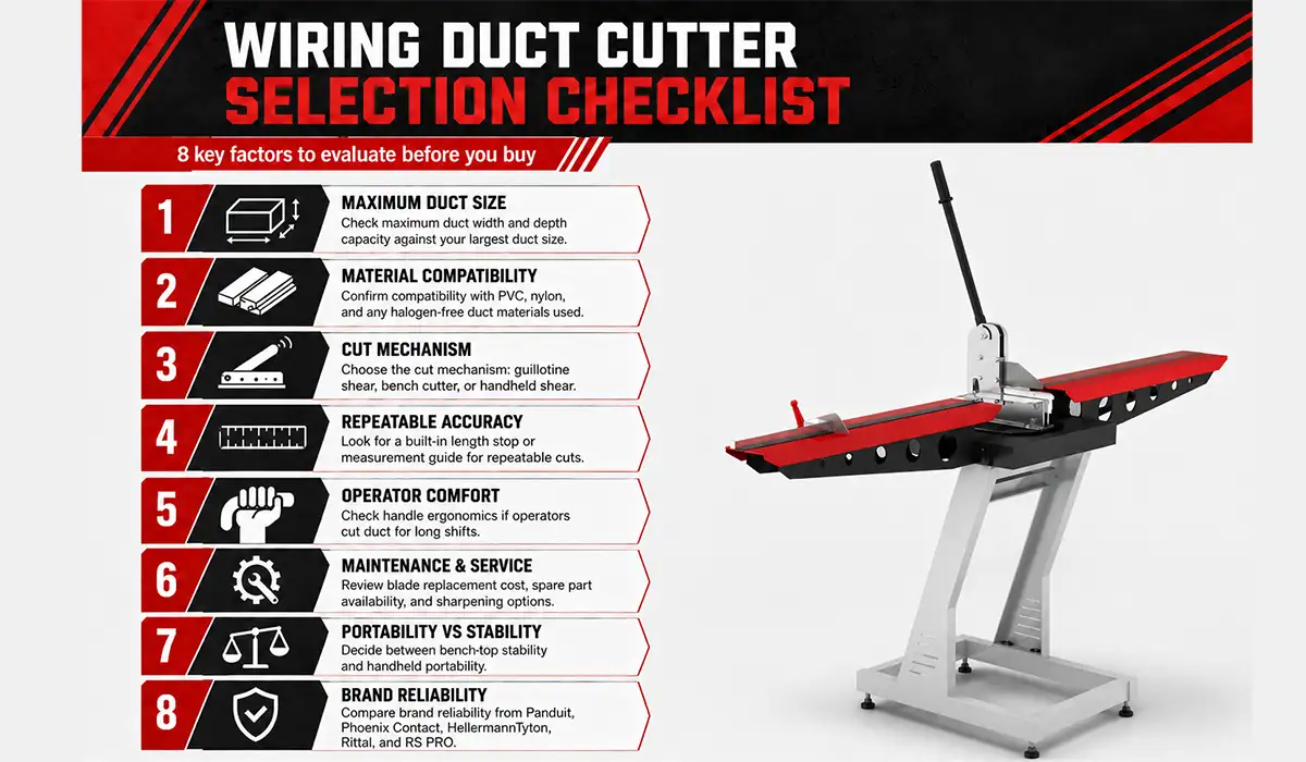
- Check maximum duct width and depth capacity against your largest duct size.
- Confirm compatibility with PVC, nylon, and any halogen-free duct materials used.
- Choose the cut mechanism: guillotine shear, bench cutter, or handheld shear.
- Look for a built-in length stop or measurement guide for repeatable cuts.
- Check handle ergonomics if operators cut duct for long shifts.
- Review blade replacement cost, spare part availability, and sharpening options.
- Decide between benchtop stability and handheld portability.
- Compare brand reliability from Panduit, Phoenix Contact, HellermannTyton, Rittal, and RS PRO.
For panel shops cutting duct daily, a benchtop guillotine-style cutter with an adjustable stop gauge is usually the most efficient investment. It gives consistent length control, clean square ends, and faster workflow than saw-based cutting. However, a handheld cutter or fine-tooth saw may still suit service teams, small workshops, and low-volume maintenance work.
A good duct system starts with the panel layout, not with the cutting bench. First, choose the duct type based on routing flexibility, protection, and appearance. Next, size the duct from wire count, outside diameter, fill ratio, and future expansion needs. Then, separate power, signal, and control runs so the cabinet remains clear and serviceable.
For most control cabinet wiring, narrow slot duct provides the best balance of flexibility and containment. Solid wall duct suits clean or signal-critical routes, while wide slot duct helps with larger bundles and dense panels. Finally, use a dedicated cutter when quality and production speed matter. Clean, organized ducting improves assembly work, reduces troubleshooting time, and gives the final panel a more professional finish.