


Transformer Busbar Fundamentals: Connection Design, Current Flow, and Reliability
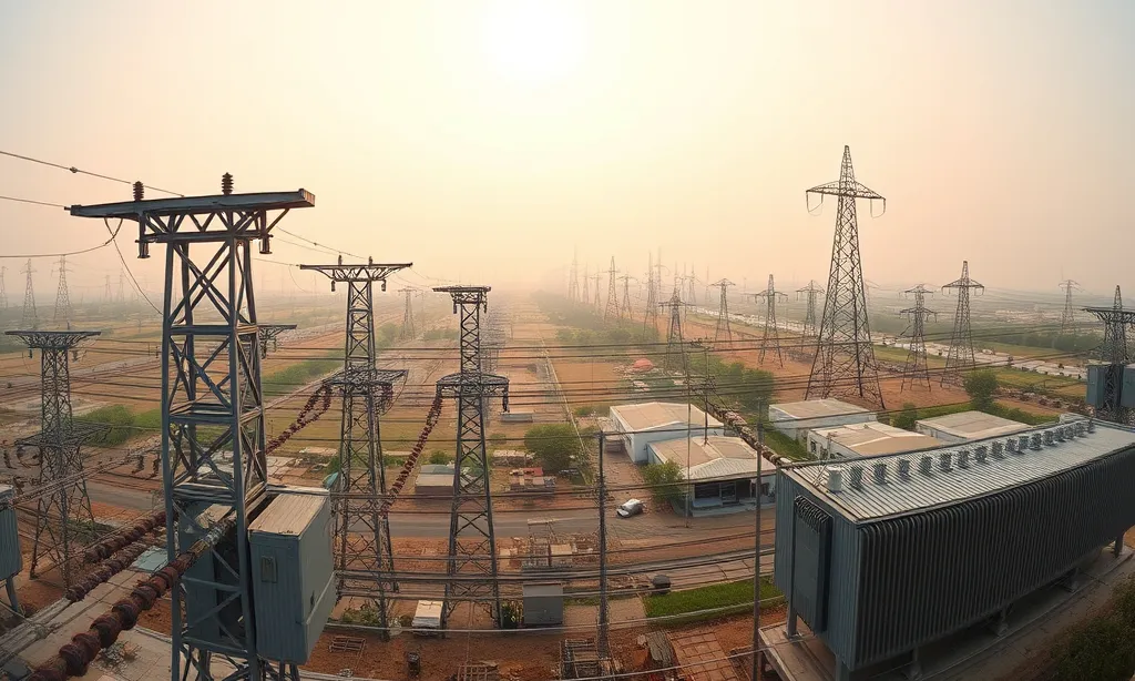
A transformer busbar is the rigid current-carrying link used to connect transformer windings, bushings, tap changers, terminals, and external power circuits. In practical engineering terms, the busbar in transformer assemblies must transfer high current with low impedance while fitting into a restricted internal space. This makes the design more demanding than ordinary panel busbars, because the connection must control heat rise, maintain insulation clearance, withstand vibration, and remain stable during short-circuit forces.
A reliable transformer busbar connection is not only a piece of copper or aluminum shaped to fit the tank. It is a coordinated electrical and mechanical component. Its cross-section must be large enough to limit voltage drop and I²R losses, its surface and joint areas must support low contact resistance, and its geometry must allow thermal expansion without stressing bushings, supports, or insulation materials. Poor busbar design can lead to overheating, loose joints, partial discharge risk, mechanical deformation, or reduced transformer service life.
In high-current transformer applications, every design detail matters. Material selection, bar thickness, bend radius, hole alignment, flatness, edge treatment, plating, and insulation coverage all affect the final performance of the transformer bus bar. This is why transformer busbar design should be evaluated as a complete system: current path, connection quality, thermal behavior, mechanical strength, electrical clearance, and fabrication accuracy must work together before the assembly can be considered reliable.
For a comprehensive understanding of busbar fabrication equipment, we highly recommend reviewing this article.
Material Selection for Transformer Busbar Connections: Copper vs. Aluminum
Material selection is one of the most important engineering decisions in any transformer busbar connection. A busbar inside a transformer must carry high current with low losses, maintain stable joint performance, resist thermal cycling, and withstand mechanical forces during fault conditions. For this reason, the choice between copper and aluminum is not only a cost decision; it affects conductivity, bar size, heat rise, connection design, insulation spacing, fabrication method, and long-term reliability.
In most transformer busbar applications, copper and aluminum are selected according to current rating, available space, weight limits, thermal performance, and joint configuration. Copper is usually preferred where compact size, high conductivity, and mechanical rigidity are critical. Aluminum is often considered where weight reduction and material cost are major design priorities. However, because aluminum has lower conductivity than copper, an aluminum transformer bus bar normally requires a larger cross-section to carry the same current.
For a comprehensive understanding of Busbar Processing Machine, we highly recommend reviewing this article.
Copper Busbars in Transformer Applications
Copper remains the preferred material for many high-current busbar transformer designs because of its excellent electrical conductivity, thermal stability, and mechanical strength. A copper busbar can carry high current in a relatively compact cross-section, which is especially valuable inside transformer tanks where space is limited and insulation clearances must be carefully controlled. This makes copper suitable for connections between windings, bushings, terminals, tap changers, and other high-load current paths.
From a technical point of view, copper also provides strong mechanical support in rigid transformer busbar connection assemblies. Its stiffness helps reduce movement under vibration and electromagnetic forces during short-circuit events. Copper also performs well at bolted joints when the contact surfaces are properly prepared, plated, and tightened to the correct torque. For critical applications, tin-plated or silver-plated copper contact areas may be used to reduce oxidation, stabilize contact resistance, and improve long-term connection reliability.
The main disadvantage of copper is cost and weight. Copper is heavier and usually more expensive than aluminum, which can increase material cost, handling effort, and total assembly weight. However, in applications where compact design, lower resistance, reduced heat generation, and high fault-duty performance are priorities, copper often provides better long-term value than a lower-cost material with larger size requirements.
For a comprehensive understanding of bending machine price, we highly recommend reviewing this article.
Aluminum Busbars in Transformer Applications
Aluminum is a practical alternative for some transformers with busbar connections, especially where weight reduction, cost control, and easier handling are important. Compared with copper, aluminum is much lighter, which can be beneficial in large transformer assemblies, transportation, and installation. This advantage becomes more significant when the busbar system is physically large or when multiple internal connections are required.
However, aluminum has lower electrical conductivity than copper, so an aluminum busbar in transformer design generally needs a larger cross-sectional area to achieve similar current-carrying performance. This can affect available space, bend geometry, support design, and insulation clearance. Engineers must also consider aluminum’s higher thermal expansion rate, lower mechanical stiffness, and greater sensitivity at connection interfaces.
The most critical point in aluminum busbar design is joint reliability. Aluminum naturally forms an oxide layer on its surface, which can increase contact resistance if not properly managed. When aluminum is connected to copper components, the design must also address galvanic corrosion risk. Proper surface preparation, compatible plating, joint compound, spring washers, and controlled tightening torque are essential for stable performance. In many cases, welded or specially treated aluminum connections may be preferred over simple bolted joints.
| Factor | Copper Transformer Busbar | Aluminum Transformer Busbar |
|---|---|---|
| Conductivity | Higher conductivity; supports compact high-current design | Lower conductivity; usually requires larger cross-section |
| Weight | Heavier | Much lighter |
| Mechanical strength | Better rigidity and joint stability | Lower stiffness; may need additional support |
| Thermal behavior | Lower resistance and better heat performance in compact sections | Higher expansion; careful thermal design required |
| Joint reliability | Strong performance with proper plating and torque | Requires oxide control, joint compound, and corrosion protection |
| Space requirement | More compact for the same current rating | Larger bar size may be needed |
| Cost profile | Higher material cost | Lower material cost, but may need larger sections and special joint treatment |
| Best use case | High-current, compact, high-reliability transformer busbar connections | Weight-sensitive or cost-sensitive transformer busbar systems |
For best engineering results, copper and aluminum should not be compared by raw material price alone. The correct choice depends on the complete transformer busbar system: current rating, voltage level, available tank space, short-circuit force, heat rise limit, joint design, surface treatment, insulation layout, and fabrication process. A lower material cost can become expensive if it causes oversized geometry, difficult bending, unstable joints, or higher maintenance risk.
| Specification | Copper | Aluminum |
|---|---|---|
| Conductivity (MS/m) | 58 | 35 |
| Density (g/cm³) | 8.9 | 2.7 |
| Thermal Expansion (10⁻⁶/°C) | 17 | 23 |
| Current Capacity (A/mm² at 50°C rise) | 1.2 | 0.8 |
| Relative Cost (per kg) | 3.5x | 1.0x |
| Typical Surface Treatment | Tin/Silver Plating | Oxide Removal + Compound |
Cross-Section Design for Transformer Busbars: Current Capacity, Flatness, and Edge Treatment
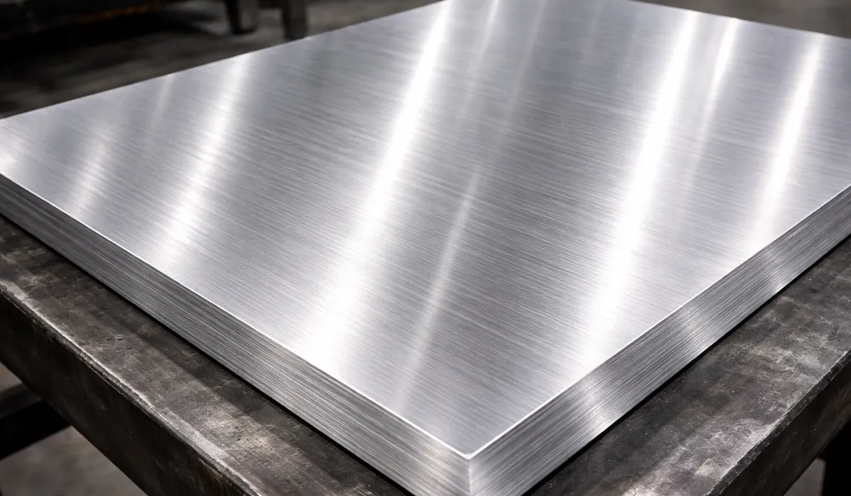
The cross-section of a transformer busbar directly affects current-carrying capacity, heat rise, voltage drop, short-circuit strength, and available installation space inside the transformer. Most transformers with busbar connections use flat rectangular copper or aluminum bars because this profile provides a large conductive area, efficient heat dissipation, and predictable mechanical behavior during fabrication. In a high-current busbar in transformer assembly, the width, thickness, and aspect ratio must be selected according to load current, allowable temperature rise, insulation clearance, bending requirements, and connection geometry. A compact cross-section may reduce space usage, but if it is undersized, it can increase resistance, create hotspots, and reduce long-term reliability.
Edge treatment is equally important in transformer bus bar design. Sharp corners, burrs, poor cut quality, and uneven surfaces can create electrical stress points, damage insulation sleeves, and weaken joint performance. For this reason, radiused edges, controlled deburring, smooth contact surfaces, and proper busbar flatness measurement should be part of the quality control process before final assembly. A reliable transformer busbar connection depends not only on material conductivity, but also on how accurately the bar is cut, punched, finished, and inspected. Proper cross-section design and edge finishing help improve electrical performance, reduce partial discharge risk, support stable bolted connections, and extend transformer service life.
Further exploration of Cross section can be found in the following recommended reading.
Radiused Edges and Burr Control in Transformer Busbars
Radiused edges and burr control are critical in any transformer busbar design because the edge profile affects both electrical insulation performance and mechanical reliability. Sharp corners on a busbar in transformer assemblies can concentrate electric stress, especially near bends, bolt holes, joint areas, and phase-to-ground clearances. In higher-voltage transformer applications, these stress points may increase the risk of partial discharge, insulation tracking, sleeve damage, or premature dielectric failure. For this reason, a properly finished transformer bus bar should not be treated as a simple cut metal strip; its edge condition is part of the insulation and reliability design.
After cutting, punching, or slotting, all edges should be deburred and inspected before the busbar is plated, insulated, or assembled. A small radius is usually preferred over a sharp edge because it reduces electric field concentration and lowers the chance of cutting into insulation sleeves or tapes during thermal movement. In many transformer busbar fabrication processes, edge radii, burr height limits, and inspection methods should be defined directly on the drawing or RFQ. This is especially important for transformer busbar connection points, where bolt holes, slots, and joint landing zones must remain smooth, flat, and free from raised burrs that could affect contact pressure or alignment.
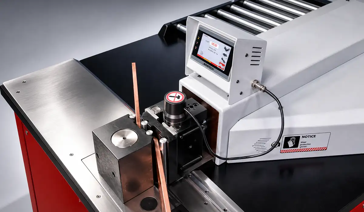
For high-quality production, burr control should be verified with a consistent inspection method rather than visual checking alone. Dial gauges, tactile inspection, magnification, and surface comparison checks can help confirm that punched holes, cut ends, and bend areas meet the required finish level. When busbar flatness measurement is also required, burrs must be removed first, because raised edges can distort measurement results and create false contact points on the inspection surface. Proper edge finishing improves insulation life, joint stability, assembly accuracy, and long-term transformer reliability.
Surface Finish for Reliable Transformer Busbar Connections
Surface finish plays a major role in the performance of a transformer busbar connection because electrical current must pass through bolted, clamped, or welded contact areas with minimal resistance. Even when the busbar material has high conductivity, poor surface preparation can create localized heating at the joint. Oxidation, contamination, uneven contact surfaces, scratches, plating defects, and insufficient flatness can all increase contact resistance and reduce long-term reliability.
For copper transformer busbars, tin plating is commonly used on joint areas to improve corrosion resistance and stabilize electrical contact over time. Silver plating may offer higher conductivity, but it is usually selected only for applications where the performance benefit justifies the additional cost and environmental considerations. For aluminum busbars, surface preparation is even more sensitive because aluminum oxide can quickly form on exposed surfaces and interfere with electrical contact. In aluminum-to-copper connections, plating selection, joint compound, washer design, and tightening torque must be carefully specified to reduce galvanic corrosion risk and maintain stable joint pressure.
A reliable bus bar transformer connection depends on more than plating alone. The contact area should be clean, smooth, flat, and properly compressed during assembly. If the surface is warped, contaminated, or uneven, the actual contact area may be much smaller than the visible joint area, causing higher resistance and heat concentration. For this reason, surface finish, contact flatness, plating thickness, cleaning procedure, and torque control should be treated as part of the same quality system. When specified correctly, these details help the transformer bus bar maintain low contact resistance, reduce hotspot formation, and support stable operation throughout the transformer’s service life.
Hole Patterns, Slots, and Tolerance Management in Transformer Busbars
Precise hole location enables repeatable assembly and ensures proper alignment with mating bushings and terminals. For transformer busbar connection designs, establish a clear datum scheme—typically the intersection of two machined edges—and dimension all features from this reference.
If you are looking for more information about Transformer types, it is recommended not to miss reading this article.
Thermal Expansion Slots
Busbars can experience temperature swings of 80-100°C between cold start and full load. A 1-meter long copper bar expands approximately 1.7mm over this range. Slotted holes (oval slots with length 3-5mm greater than bolt diameter) at one end of the connection allow movement without stressing the joint or insulation.
Real-world implementation: A 138 kV transformer builder uses 12mm diameter bolts in 18mm × 12mm slots for connections exceeding 500mm length. The long axis of the slot aligns with the thermal expansion direction, and hardened washers distribute clamping force across the slot width.
Transformer busbars typically require multiple bends to route current through the tank while maintaining electrical clearances. For cold bending, half-hard copper (H02) needs a minimum radius of 1.5× material thickness, while hardened aluminum requires 2-3×. Always run sample bends before production — real-world performance often differs from supplier recommendations.
All metals spring back 2-6° after bending. Modern hydraulic benders compensate automatically, but the first article should always be measured under both no-load and bolted conditions to confirm the final angle. For multi-plane parts, bend sequence matters — each bend shifts reference edges and carries cumulative error forward. Punch all holes in the flat pattern before any bending to preserve hole-to-hole accuracy.
Insulation must keep the busbar electrically isolated from adjacent phases, grounded walls, and structural parts. Poor insulation leads to flashover, partial discharge, or full dielectric failure. Fiberglass sleeves, polyester tapes, and epoxy barriers are common choices. The insulation system must survive oil, heat, vibration, and thermal cycling — and must remain intact after cutting, punching, and bending.
Clearance and creepage requirements depend on voltage level and environment. A 35 kV indoor busbar needs at least 75mm air clearance and 100mm creepage. Outdoor or polluted sites require 50-100% more. Sharp edges concentrate electric fields and trigger corona — rounding edges from 2mm to 5mm radius can eliminate discharge risk entirely.
RFQ Guide for Transformer Busbar Connections: Drawings, Tolerances, and Quality Requirements
A complete RFQ for a transformer busbar connection should give the supplier enough technical information to understand the part geometry, material requirements, processing sequence, inspection needs, and delivery expectations before quotation. In transformer applications, a busbar is not a generic metal component. A busbar in transformer assembly must carry high current, fit within limited internal space, maintain insulation clearance, and align accurately with bushings, terminals, supports, and winding connections. Missing details in the RFQ can lead to inaccurate pricing, longer lead times, repeated revisions, and costly manufacturing errors.
For the most accurate quote, the RFQ should describe the complete transformer busbar system, not only the bar size. Suppliers need to know the required material, thickness, width, bend geometry, hole pattern, slot dimensions, surface finish, plating, insulation, flatness tolerance, and inspection standard. When these details are provided from the beginning, the supplier can evaluate manufacturability, select the correct punching, cutting, and bending process, estimate tooling requirements, and calculate a realistic production cost.
Technical Documentation for Transformer Busbar RFQs
A strong RFQ should include a 3D STEP or IGES model when available, along with a detailed 2D drawing or flat pattern. The drawing should clearly show all dimensions, bend lines, bend direction, inside bend radius, hole locations, slot geometry, datum references, and tolerance requirements. For complex transformer bus bar parts, the bend sequence should also be defined because multi-plane bending can affect final alignment and accumulated dimensional error.
Material specification should be precise. Instead of writing only “copper” or “aluminum,” define the material grade, temper, conductivity requirement, thickness, width, and dimensional tolerance. For example, a copper transformer busbar connection may require a specific copper grade, half-hard or annealed temper, tin-plated joint areas, and controlled burr height after punching. These details help prevent supplier assumptions that could affect current-carrying performance, mechanical strength, and long-term reliability.
Finish, Plating, Insulation, and Edge Requirements
The RFQ should clearly define all finishing and processing requirements because they directly affect the performance of transformers with busbar connections. Edge treatment should include the required corner radius, maximum burr height, deburring method, and whether edges must be hand-finished, tumbled, or machined. This is especially important near bolt holes, bend radii, and joint landing areas, where burrs or sharp edges can damage insulation or increase electrical stress.
Surface finish and plating should also be specified. If tin or silver plating is required, state the plating type, thickness, coverage area, and whether plating is applied to the full busbar or only to contact surfaces. Insulation requirements should include material class, sleeve or tape type, number of layers, overlap distance, clearance zones, and whether sleeving must be applied before or after bending. For high-reliability busbar transformer assemblies, these details reduce the risk of oxidation, poor contact resistance, insulation failure, and field rework.
Quality Control, Flatness Measurement, and Delivery Parameters
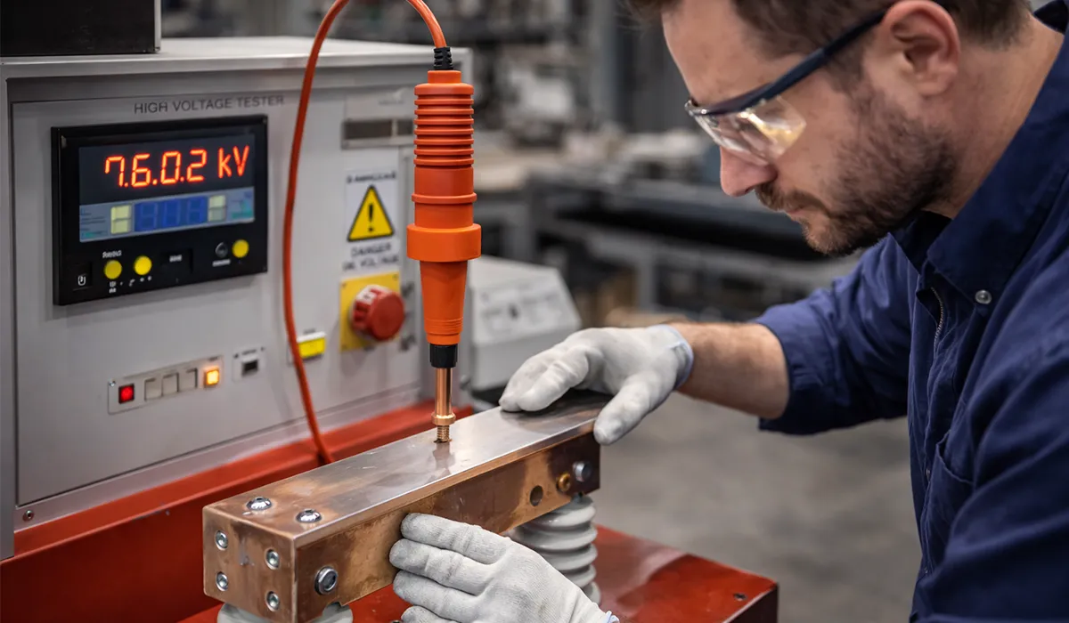
Quality expectations should be part of the RFQ, not added after production begins. The buyer should define required inspection records such as dimensional reports, material certificates, plating thickness reports, burr-height checks, bend-angle verification, and hi-pot or dielectric testing where applicable. If the design requires busbar flatness measurement, the acceptable flatness tolerance, measurement method, and inspection surface should be stated clearly. This is important because poor flatness can reduce contact area, create uneven bolt pressure, and increase heating at the transformer busbar connection.
Commercial details are also necessary for accurate pricing. The RFQ should state prototype quantity, pilot batch quantity, production volume, delivery schedule, packaging requirements, labeling method, and traceability expectations. For copper and aluminum busbars, packaging should prevent oxidation, surface scratches, bending damage, and contamination before assembly. A well-prepared RFQ allows the supplier to quote faster, reduce uncertainty, and deliver transformer bus bar components that meet both electrical and mechanical requirements.
Conclusion
From my engineering point of view, a transformer busbar connection should never be treated as a simple conductive link. It is a critical current-carrying structure that directly affects transformer efficiency, thermal behavior, insulation reliability, mechanical stability, and long-term service life. Throughout this guide, I have explained how material selection, copper versus aluminum performance, cross-section design, edge treatment, hole tolerances, bending accuracy, surface finish, insulation, flatness control, and quality inspection all work together to determine the reliability of a busbar in transformer applications. A well-designed transformer busbar reduces losses, prevents hotspots, withstands fault forces, and supports safe operation under demanding electrical conditions. For manufacturers, panel builders, and electrical engineers, the best results come from specifying every detail clearly—from drawings and tolerances to plating, sleeving, testing, and RFQ documentation—so the final transformer bus bar is not only manufacturable, but also reliable, safe, and ready for decades of operation.
Frequently Asked Questions


Transformer busbars are essential for handling high currents safely and efficiently. Their solid design improves conductivity and helps reduce power losses in electrical systems.