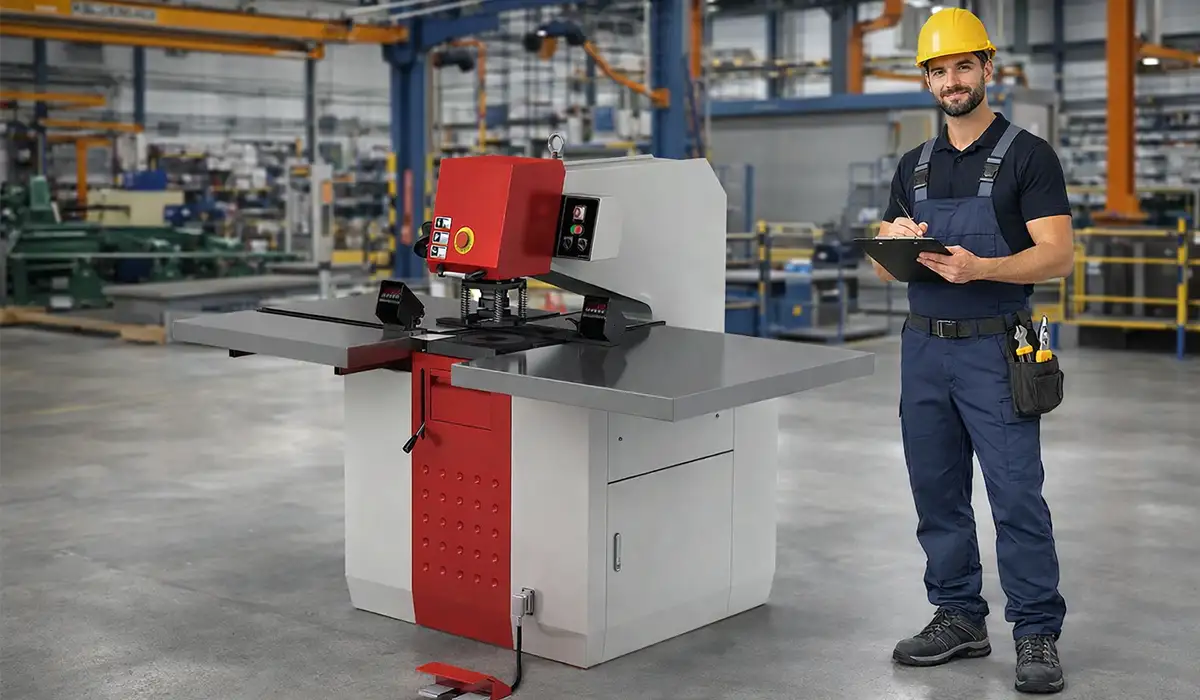
What Is a Punching Machine Tool? (And How Punch Press Tooling Works)
A punching machine tool is the complete cutting assembly — punch, die, stripper, and guide — installed in a mechanical, hydraulic, or servo-driven press to shear or form sheet metal. The punch (male) drives material through the die (female), and the gap between them, called die clearance, controls whether the slug separates cleanly or tears.
Punch press tooling is engineered for impact loads that can exceed 200 kN on a single 12 mm hole in mild steel. When the ram descends, the punch tooling penetrates roughly one-third of the material thickness before fracture propagates across the remaining cross-section. That fracture line, not the punch itself, defines edge quality — which is why punch press tools must be matched to the material, not just the hole size.
Compared to laser or waterjet, punch press tools win on three fronts: cycle time (hits per minute), the ability to form features like louvers, lances, dimples and knockouts in one stroke, and lower cost-per-hole at volume. That’s why the punching machine tool remains the backbone of HVAC, electrical enclosure, automotive bracket, and steel building component production.
The two factors that decide whether punch press tooling delivers on that promise are press rigidity and tool hardness. Tooling is typically D2 or M2 tool steel at 60–62 HRC for general work, or tungsten carbide for abrasive stainless and high-volume runs.
Further exploration of topic Punching Machine Tooling and Dies can be found in the following recommended reading.
Anatomy of a Punching Machine Tool: Punch, Die, Stripper & Guide
Every punching machine tool, regardless of brand or station style, is built from four critical components — and weakness in any one of them shows up as burr, slug pulling, or premature tool failure.
Punch: the male cutting member, usually with a shear angle ground into its face to reduce peak tonnage by 20–40%. Die: the female counterpart, sized larger than the punch by the calculated die clearance. Stripper plate: holds the sheet flat against the die during the upstroke so the punch retracts cleanly; spring-loaded strippers also reduce burr by maintaining contact pressure. Guides and guide bushings: maintain punch-to-die concentricity within 0.01–0.02 mm — anything looser and the punch will eventually contact the die wall, chipping both. Together, these four elements form the punch and die tooling assembly that defines your part quality.
Punch vs Die: The Difference Between Punch and Die Explained
One of the most-searched questions in metal fabrication is also the most misunderstood: what’s the difference between a punch and a die? The short answer — the punch moves and cuts; the die stays still and shapes.
In any punching machine tool, the punch is the active, male component mounted to the press ram. It descends under load and drives into the sheet. The die is the passive, female component fixed to the bolster or turret station. It supports the sheet from below and gives the punch a precisely sized opening to push the slug into.
The practical implications matter on the shop floor:
- Sizing: the punch is sized to the desired hole; the die is sized to the punch plus 2× die clearance.
- Wear pattern: punches typically dull at the cutting edge first; dies usually fail at the entry radius or by enlargement from slug abrasion.
- Cost: a punch is usually replaced 2–3× before its matching die — useful to know when ordering spares.
- Forming vs cutting: in a forming punch and die set (covered in the next section), the same logic applies, but neither component cuts — they deform the sheet between them.
If you remember nothing else: in the punch vs die relationship, the punch is what you swap most often, and the die is what you protect most carefully.
Forming Punch and Die: When Tooling Shapes Instead of Cuts
Not every punching machine tool removes material. A forming punch and die set deforms the sheet — bending, drawing, embossing, or extruding — without separating a slug. This is how single-station turret punches produce louvers, countersinks, dimples, hinges, knockouts, threaded extrusions, and ribs that would otherwise require a separate brake or press operation.
A forming punch and die works on a fundamentally different stress regime than a cutting tool. Instead of driving fracture, it applies controlled plastic deformation. That means:
- Die clearance is typically larger than for cutting (often 1.0–1.5× material thickness, vs 15–25% for cutting).
- Up-form vs down-form matters: most CNC turrets are limited to ~6 mm of up-form height because the formed feature has to clear adjacent stations.
- Material flow must be considered — high tensile materials (stainless, HSLA steel) crack at sharp inside radii; the forming punch radius should be ≥1× material thickness for safe forming.
- Spring-back can reach 3–8° on harder grades, requiring over-form compensation built into the punch geometry.
Forming punches are usually shorter and stubbier than cutting punches, with polished radii rather than ground cutting edges. The single biggest mistake we see in the field: shops trying to form 3 mm stainless on a turret rated for 2 mm — the tooling survives one or two hits, then galls or cracks. Always verify the press tonnage against the forming load curve before committing to a forming punch and die.
Types of Punch and Die Tooling: Blanking, Piercing, Progressive & Compound
Punch and die tooling is not one product — it’s a family of designs, each optimized for a different operation. Choosing the right type is the single biggest lever on cost-per-part for any punching machine tool, and getting it wrong is the most common reason job shops over-tonnage their presses.
The five categories every fabricator should know:
- Blanking dies — the punched-out piece is the part; the surrounding sheet is scrap. Used for washers, gaskets, and stamped blanks.
- Piercing dies — the hole is the feature; the slug is scrap. Used for vent holes, bolt holes, and electronic chassis cutouts.
- Progressive dies — a strip travels through multiple stations on a single press, gaining a new feature at each stroke until a finished part drops at the end.
- Compound dies — perform two or more operations (typically blanking + piercing) in one station, one stroke. Best when concentricity between features must be near-perfect.
- Forming/embossing dies — shape rather than cut (see forming section above).
A separate axis worth understanding: punch press tooling vs stamping dies. Punch press tools are usually modular cartridges sized for turret or single-station presses (Thick Turret, Thin Turret, Trumpf Multi-Tool). Stamping dies are dedicated, custom-built tool sets bolted into a stamping press for one part number. Punch press tools win for variety; stamping dies win for volume.
Tooling kits for punch presses allow operators to switch between punch die types and functions quickly. This versatility is essential for job shops that handle precision punching dies for different clients on the same shift.
Blanking Dies vs Piercing Dies
Blanking and piercing look identical from across the shop floor — both use a punch driving through a die — but they’re optimized for opposite outcomes. In blanking, the slug is the product; in piercing, the slug is the scrap.
That single difference changes everything downstream. Blanking dies are designed with the die opening sized to the finished part dimension, with clearance applied to the punch (smaller than the die). Piercing dies are the reverse — the punch is sized to the hole, and clearance is applied to the die (larger than the punch). Get this backward and your parts will be 1–2× the die clearance out of spec.
Both operations use the same punch press tooling family, but blanking typically runs slightly tighter clearance (15–18% of material thickness) to maximize blank edge quality, while piercing can tolerate 20–25% clearance because the slug quality doesn’t matter.
Progressive Dies Explained
A progressive die is the high-volume answer to the question “how do I make 10,000 finished parts a shift without 10,000 setups?” A coiled strip feeds through 4–20 stations in a single die set, and every press stroke advances the strip one pitch while every station simultaneously performs its operation — pierce, blank, form, bend, draw, coin, cut-off.
The math is unforgiving in progressive’s favor: a 12-station progressive die at 120 strokes per minute outputs 14,400 finished parts per hour — work that a single-station punching machine tool would need a full shift to match. Used in automotive clips, terminal blocks, electrical contacts, and brackets, progressive dies cost more upfront (often $30k–$150k for tooling) but cut piece-cost to a fraction of stand-alone punch press tools at the right volume.
How to Select Punch Press Tooling for Your Machine
Selecting punch press tooling is a four-variable problem: part geometry, material, machine, and volume. Mishandle any one and you’ll either over-spend on tooling or under-spec it and chase failures for the next 12 months.
1. Part geometry first. The punch shape (round, square, obround, D-sub, hexagon, custom) is dictated by the feature you need. But minimum hole-to-thickness ratio matters: most tooling makers require hole diameter ≥ 1× material thickness for standard tool steel punches, or ≥ 0.5× for carbide.
2. Material decides tool steel grade. Match the punch press tools to what you’re cutting (see next section).
3. Machine compatibility is non-negotiable. Punch press tooling must match your station style — Thick Turret (Style A/B/C/D/E), Thin Turret, or Trumpf-style. Wrong style = the tool simply will not fit the turret.
4. Tonnage budget. Required tonnage = perimeter × thickness × shear strength × 0.0098 (for kN). If the calculated load exceeds 80% of press rated tonnage, downsize the hole or add a shear angle to the punch face.
5. Clearance. A calculated percentage of material thickness, typically: mild steel 15–20%, stainless 20–25%, aluminum 10–15%, copper/brass 8–12%. Too tight → secondary shear, high tonnage, fast wear. Too loose → rollover, large burr, slug pulling.
The best practical strategy for a new setup: invest in a punch tooling kit covering standard rounds (3 mm to 50 mm) plus the four most-used custom shapes for your work — then add specialty tools as orders demand.
Punch and Die Material in Press Tool Selection: Steel Grades, Carbide & Tonnage
Choosing the right punch and die material in press tool design is where most shops either save thousands or burn through tooling budget. Tool steel and carbide each solve different problems, and using the wrong one for your workpiece is the fastest route to premature failure.
A2 tool steel (air-hardened, ~58–60 HRC): a forgiving general-purpose grade. Good toughness, moderate wear resistance. Use for short runs on mild steel and aluminum.
D2 tool steel (high carbon/chromium, 60–62 HRC): the workhorse grade for most punch and die tooling. Excellent wear resistance, acceptable toughness. Standard choice for mild steel, galvanized steel, and most stainless under 3 mm.
M2 high-speed steel (62–64 HRC): higher hot-hardness; resists tempering when running fast cycle rates or hot workpieces. Used on high-strength steels and high-speed turret applications.
PM (powder metallurgy) grades like CPM-10V, ASP-23, Vanadis 4: 2–5× the wear life of D2 on abrasive stainless. Costs 30–50% more but worth it on volume runs.
Tungsten carbide: 8–20× the wear life of D2 on stainless and silicon steel. Brittle — will chip if alignment, clearance, or stripping is wrong. Use only on stable, well-maintained machines.
Coatings (TiN, TiCN, TiAlN, CrN): add 2–4× life on the right combinations. TiCN for galvanized; TiAlN for stainless; CrN for aluminum (prevents galling).
Tonnage logic runs alongside material choice. Press tonnage required = (punch perimeter in mm) × (material thickness in mm) × (shear strength in N/mm²) ÷ 1000, expressed in kN. Always keep working tonnage at ≤80% of press rating to preserve bearings, ram alignment, and die life.
Manual vs CNC Punch Press Tools: Which System Fits Your Shop?
The split between manual and CNC punch press tools isn’t about modernity — it’s about volume, repeatability, and labor cost.
Manual punch press tools sit in single-station ironworkers, hand-loaded fly presses, and notchers. They’re simple, robust, and cheap (a basic punch and die set runs $80–$400). They make sense for prototyping, repair work, on-site fabrication, and runs under 100 parts.
CNC punch press tools live in turret presses (Amada, Trumpf, Prima Power, Mate) and are housed in indexable cartridges — Thick Turret, Thin Turret, or Trumpf Multi-Tool. They self-rotate (auto-index) for slot orientation, support nibbling (overlapping hits to cut any shape), and change automatically between stations in under one second.
Decision rule of thumb: under 500 parts/year per geometry, manual punch press tools usually win on capital cost. Over 2,000 parts/year, CNC wins on labor and consistency. In between, the deciding factor is how many different part geometries you run — CNC’s setup advantage compounds the more SKUs you handle.
Punch Tooling for Steel Building Structures: Beams, Plates & Connection Holes
Steel building fabrication has different requirements than sheet metal work, and punch tooling for steel building structures is a specialty category in its own right. The workpieces are thicker (typically 6–25 mm), the holes are larger (often M16 to M30 bolt clearance), and the tooling must survive thousands of cycles on hot-rolled structural steel (S275, S355, A36, A572).
The dominant machines in this segment are structural CNC line drills/punches and hydraulic ironworkers like the Geka, Sunrise, Peddinghaus, and similar lines. Their punch tooling shares core design principles with sheet metal tools but with key differences:
- Heavier punch shanks (Ø 40–80 mm) to handle 60–150 ton hits.
- Larger shear angles (4–8°) ground into the punch face to spread the load across the stroke and reduce peak tonnage by 30–50%.
- Carbide-tipped or PM steel construction because mill scale on hot-rolled steel is highly abrasive.
- Generous clearances (20–25% of material thickness) — structural connections don’t need cosmetic edges, just bolt clearance to AISC or EN 1090 tolerances.
- Slug ejection design matters more — slugs from 20 mm plate weigh hundreds of grams and must drop clear of the die without jamming.
The most common failure mode in punch tooling for steel building structures isn’t wear — it’s chipping at the cutting edge when the operator tries to punch material harder than the tool was rated for (e.g., S460 high-strength steel on tools spec’d for S275). Always verify the steel grade against the tooling manufacturer’s hardness rating before the first hit.
How Tooling Managers Reduce Downtime in Punching and Piercing Operations
Tooling managers who reduce downtime in punching and piercing operations don’t do it with one big change — they do it through a small set of disciplined practices that compound. Unplanned tooling failure typically accounts for 15–30% of total downtime on a CNC punch press; cutting that in half is a realistic, measurable goal.
1. Scheduled sharpening at hit-count thresholds, not on failure. Set re-sharpening intervals based on hits-per-tool (typically 50,000–150,000 hits for D2 on mild steel; 200,000+ for coated tooling). Sharpening before the burr exceeds 10% of material thickness preserves the punch geometry — sharpening after it dulls removes 3–5× more material and shortens tool life by half.
2. Per-tool log books. Every punch press tool gets a card: install date, hit count, sharpenings, material used, observed issues. Without this, you’re guessing.
3. Standardize clearances and grade across SKUs. Every unique clearance means a unique die, more sharpening drift, more inventory, longer changeovers. Consolidating tooling cuts downtime more than buying faster machines.
4. Treat slug pulling as an emergency. A pulled slug that returns up through the die and lands on the sheet will destroy the next punch, next die, and possibly the turret station. Use slug-retention dies (knurled or stepped die openings) on stainless and oily material.
5. Storage discipline. Tools stored loose in drawers chip within weeks. Use foam-cut cases or labeled cabinet positions. Oil before storage. Inspect under magnification at insertion, not at failure.
6. Operator training as a downtime lever. Operators who can recognize the four early-warning signs — rising noise pitch, burr asymmetry, slug pulling, and tonnage drift — flag tools before catastrophic failure, not after.
Shops that adopt all six see typical downtime reductions of 20–40% within two quarters, with no capital spend.
Preventing Punch Press Tool Wear and Extending Tool Life
Wear on punch press tools is rarely sudden — it’s the accumulation of micro-cracks, edge rounding, and heat-induced tempering loss over thousands of hits. Three practices flatten that wear curve.
Lubrication. Every hit generates heat at the punch-to-material interface, often reaching 200–400°C locally. Without lubrication, that heat tempers the punch surface and accelerates wear. Automated lubrication on CNC presses handles the punch shank; on manual presses, a light film of forming oil or chlorinated paraffin lubricant on the punch body before each batch is sufficient.
Pre-emptive sharpening. Sharpening at 80% of expected tool life — not at failure — removes only 0.1–0.2 mm of material per cycle, leaving 8–15 total sharpenings possible per punch. Sharpening after visible burr or chip damage removes 0.5 mm+ and yields only 3–5 sharpenings before the punch goes below minimum working length.
Alignment checks. Quarterly dial-indicator checks of punch-to-die concentricity (target ≤0.02 mm runout) catch misalignment before it shows up as one-sided edge wear or chipped die corners.
Troubleshooting Punch and Die Setup Errors
Most “tooling problems” on a punch press are actually setup problems. Five symptoms account for nearly all field service calls:
- Asymmetric burr (high on one side, low on the other): punch and die are misaligned. Check turret station seating, debris under the die, and worn punch guide bushings.
- Uniform large burr all around: die clearance is too loose for the material. Recalculate using the correct shear-strength factor for the actual grade.
- Excessive tonnage for the hole size: clearance too tight, or punch face dull. Add a shear angle (single or double) to drop peak tonnage by 30–40%.
- Slug pulling: vacuum effect on thin or oily sheet. Switch to slug-retention dies (knurled, stepped, or shimmed) or apply slug-ejector pins to the punch.
- Punch sticking (stripping failure): stripper spring weak, stripper plate misadjusted, or the punch face is so dull the material galls onto it. Replace springs first; sharpen punch second.
The diagnostic sequence in the field is always: clean the station, verify clearance, check alignment, sharpen — in that order. Jumping straight to sharpening masks the root cause.
Punch and Die Tooling Comparison Table
Use the comparison below to match the right punch and die tooling category to your part geometry and production volume. Each row reflects real-world selection criteria used by tooling managers when specifying punch press tools for new jobs.
| Common Uses | Benefits | Material Compatibility | Application | Function | Die Type |
|---|---|---|---|---|---|
| Washers, flat gears, brackets | High material efficiency, minimal scrap | Steel, Aluminum, Copper | Creating standalone shapes where the cutout is the product | Cuts out a complete part/shape from the sheet | Blanking Dies |
| Vents, bolt holes, electronic chassis | High precision, faster than drilling | All fabrication metals (esp. thin sheets) | Drilling holes, slots, or cutouts where the sheet is the product | Makes holes or openings in sheets | Piercing Dies |
| Automotive clips, electrical connectors | Extremely fast production, low labor cost per part | Coiled Steel, Brass, Alloys | High-volume production of complex parts | Performs multiple operations (cut, bend, form) in one stroke sequence | Progressive Dies |
| Flanges, washers with holes | Reduces tool changeover, ensures concentricity | Ferrous and Non-ferrous metals | Simultaneous cutting and hole making | Combines blanking and piercing in one station | Combination Dies |
| Intricate mechanical parts, clock gears | High accuracy for flat parts, saves time | Flat materials, Steel | Parts requiring complex geometry in one hit | Performs cutting and forming (bending) in one tool | Compound Dies |
Conclusion
The punching machine tool is the most leveraged investment in any fabrication shop — not because the tooling itself is expensive, but because every decision around it (material grade, clearance, alignment, sharpening interval) compounds across millions of hits. Shops that understand the difference between punch and die, match punch and die material in press tool selection to the workpiece, choose between manual and CNC punch press tools by volume, and run a disciplined downtime-reduction program for punching and piercing routinely cut cost-per-part by 20–40% over shops that don’t. Whether you’re tooling up for sheet metal, structural steel building components, or progressive high-volume work, the principles are the same: select with intent, set up with precision, and maintain with discipline. The punching machine tool rewards both.