


What Is Copper Busbar Bending and Why It Matters in Electrical Assemblies
Copper busbar bending is the controlled cold-forming process used to shape copper conductors into the specific angles, offsets, and curves required by switchgear, panelboards, battery packs, and power distribution assemblies. Done correctly, busbar bending produces clean 90-degree corners, tight offsets, and edge-wise turns without cracks, surface marks, or dimensional drift. Done poorly, even a single bad bend can cause hot spots, mechanical fatigue, or full electrical failure once the busbar is under load.
Three forces work against every copper busbar machine bend:
- Work hardening — Copper stiffens as it deforms, raising yield strength but reducing ductility.
- Springback — The bar partially returns toward its original shape once the bending force is released.
- Surface marking — Clamps, dies, and pressure pads can leave scratches that compromise plating, insulation contact, or aesthetic finish.
This guide walks through every variable that controls bend quality: minimum bend radius, springback compensation, annealing temperatures, mark-free tooling, and the CNC copper busbar bending machines that automate the entire process. By the end, you’ll have the practical framework to specify, validate, and inspect copper busbar bends with confidence.
If you are looking for more information about Busbar processing machine, it is recommended not to miss reading this article.
Copper Busbar vs Aluminum Busbar Bending: Material Behavior Compared
The choice between copper and aluminum drives every downstream decision in busbar bending — die selection, force calculation, springback compensation, and mark-prevention strategy. Here is how the two materials compare in real bending operations:
Copper busbar behavior:
- High electrical conductivity (~58 MS/m) and high tensile strength
- Work-hardens rapidly during deformation
- Hard-temper copper allows only ~5% elongation before cracking
- Annealed copper can deform up to ~45%
- Surface marks easily — cosmetic finish is harder to maintain
Aluminum busbar behavior:
- Lower conductivity (~37 MS/m) but ~70% lighter than copper by volume
- Softer, more ductile, easier to bend at the same thickness
- Springs back less than hard copper
- Surface oxidizes quickly — bending must be followed by joint preparation
- Lower tooling force requirement, longer die life
For copper busbars, three operational rules emerge from this comparison:
- Anneal between successive bends. Heating copper to 400–700°C restores ductility lost to work hardening. Important: many shop standards cap in-process heating at 250°C to avoid altering surface plating — full annealing happens separately.
- Use mark-free tooling. Protective films, polyurethane pads, shims, and radiused clamps distribute pressure and prevent permanent surface scratches.
- Apply lubrication for high-speed bending. Drawing oil or PTFE film reduces friction between the bar and tooling, extending both die and busbar surface life.
For engineers verifying bending rules beyond vendor catalogs, the U.S. National Electrical Code (NEC) — specifically NFPA 70 Article 366 — defines required busway clearances and conductor bends for copper and aluminum busbars used in switchgear and panel assemblies.
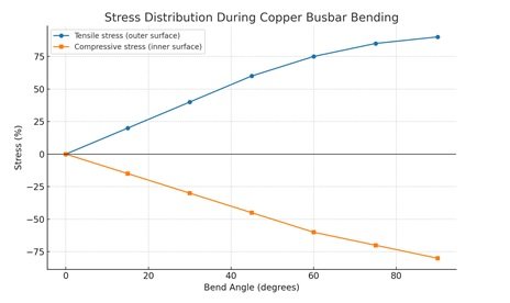
Chart 2: Stress Distribution During Bending
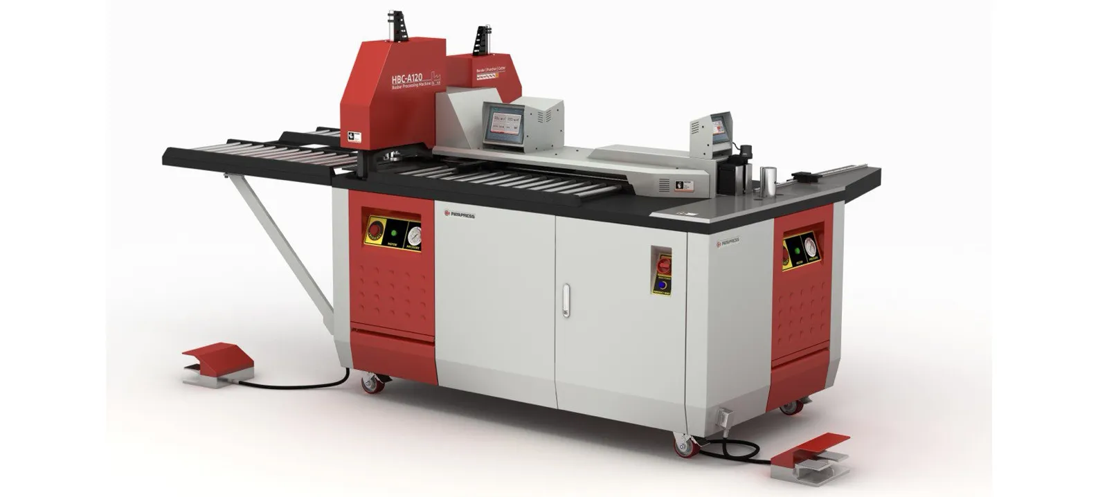
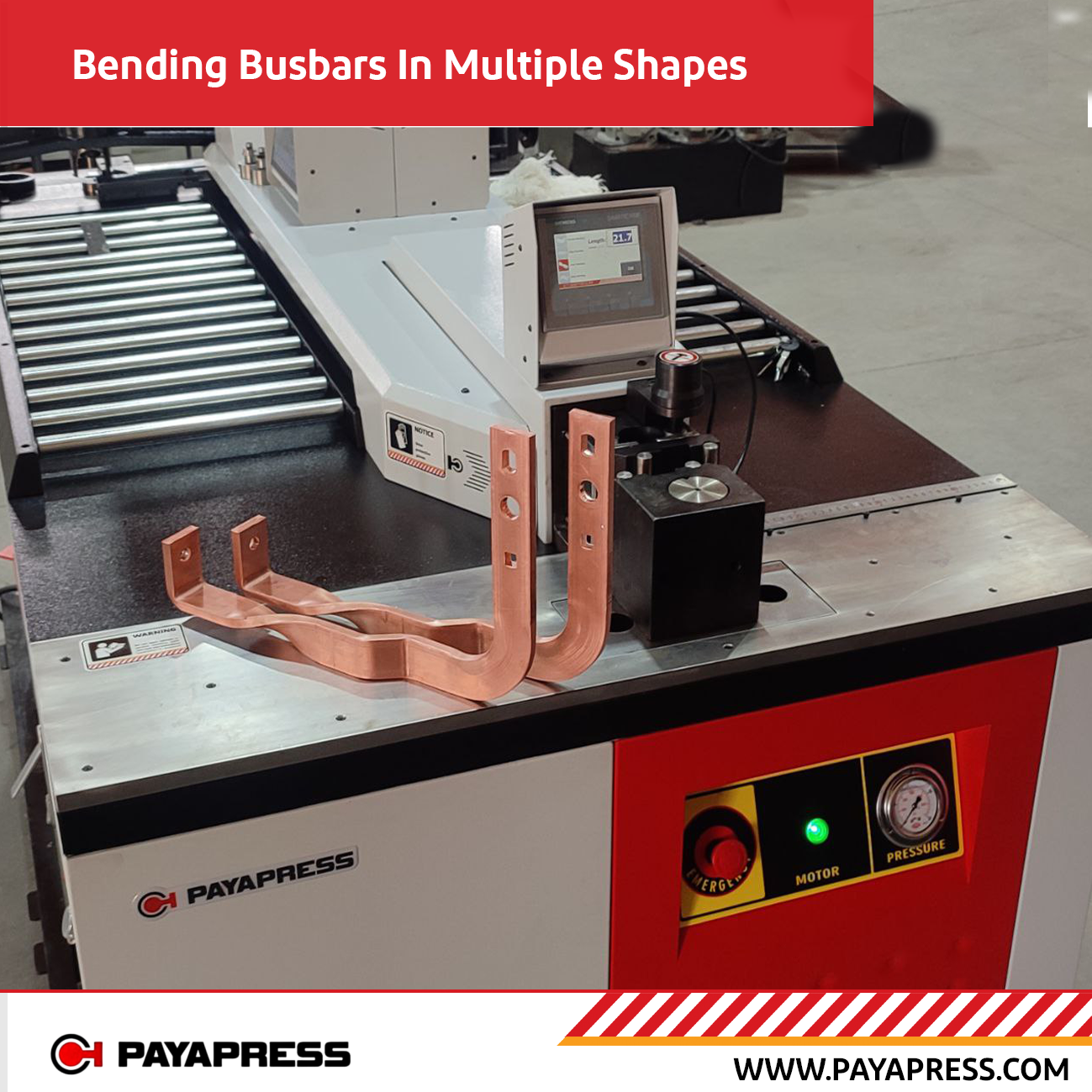
A Busbar Bending Machine is essential for producing accurate copper busbar bends used in switchgear, panelboards, battery systems, and power distribution assemblies. Since copper can work-harden, spring back, or develop surface marks during bending, the right machine helps control bend radius, angle accuracy, tooling pressure, and repeatability. Whether hydraulic, CNC, or hybrid 3-in-1, a quality busbar bending machine improves bend consistency, reduces cracks and rework, and supports reliable electrical performance in demanding busbar fabrication projects.
Minimum Bend Radius for Copper Busbar: How to Calculate R_min Without Guesswork
The minimum bend radius (R_min) is the single most critical specification in copper busbar bending. Pick a radius too tight and the outer fibers crack; pick it too loose and dimensions drift, fitment fails, and the busbar consumes more enclosure space than designed. The widely accepted industry rule for copper busbar bending is:
R_min = 1× to 2× busbar thickness (T)
The exact multiplier depends on three variables:
| Busbar Thickness | Recommended R_min | Why |
|---|---|---|
| Thin copper busbar (1–3 mm) | ~1× thickness | High ductility-to-thickness ratio handles tight radii |
| Medium copper busbar (3–10 mm) | 1.5× thickness | Balanced stress distribution |
| Thick copper busbar (10 mm+) | 1.5–2× thickness | Higher outer-fiber strain requires larger radius to avoid cracking |
Temper also matters. Annealed copper tolerates radii close to 1× thickness. Hard-temper or half-hard copper requires 1.5× or more to avoid surface cracking on the outer bend.
Practical workflow for hitting R_min reliably:
- Start with the vendor’s published minimum radius for your specific temper and thickness.
- Run trial bends on coupons cut from the same lot as production stock.
- Inspect outer-fiber surface under magnification for micro-cracks.
- Add a 10–15% margin for dynamic applications such as EV battery packs or systems exposed to vibration.
- Enforce QA gates on the first article, mid-run, and final inspection.
Hole-to-edge spacing matters too. Holes and slots placed too close to the bend line act as stress concentrators, causing tear-out or distortion under bending force. Design hole centers at least 2× hole diameter away from the inside bend tangent line, and review bend-line clearance early in the CAD stage to prevent costly rework.
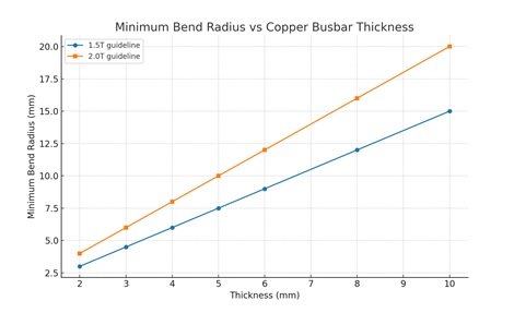
Chart 1: Minimum Bend Radius vs Thickness
How to Anneal Copper Busbar for Bending and Shaping Machines
Annealing copper before or between bends restores the ductility that work hardening removes — the difference between a busbar that bends cleanly and one that cracks on the outer radius. For shops running copper through bending and shaping machines, annealing is one of the most reliable techniques to push past R_min limits without damage.
Recommended annealing parameters for copper busbar:
| Parameter | Target Range |
|---|---|
| Heating temperature | 500–700°C (the most common production range) |
| Soak time | 30 minutes to 2 hours, depending on thickness |
| Cooling method | Slow air cooling — quenching is acceptable but unnecessary for pure copper |
Step-by-step process to anneal copper for bending:
- Clean the busbar. Remove oils, oxides, and surface debris that could carbonize during heating.
- Heat uniformly. Use a furnace, induction heater, or oxy-fuel torch with a defocused flame. Copper transfers heat extremely fast, so the entire bar must reach soak temperature — not just the bend zone.
- Hold at temperature. Maintain 500–700°C for 30 minutes to 2 hours. Watch for a dull cherry-red glow as a visual cue around 700°C.
- Cool slowly. Let the bar return to room temperature in still air. Unlike steel, copper does not require quenching — and slow cooling produces the softest, most ductile result.
- Deburr and inspect. Check for surface oxidation, scale, and dimensional warping before sending the bar into the bending machine.
Important production note: In-process bending operations on already-finished busbars should stay below 250°C to protect tin or silver plating. Full 500–700°C annealing is performed before plating or as a separate restoration step on bare copper.
After annealing, hard-temper copper that allowed only 5% elongation can deform up to 45% without cracking — making complex geometries, tight radii, and multi-axis bends practical on standard CNC busbar bending machines.
How to Prevent Copper Busbar Marking During Bending: Mark-Free Tooling & Edge Quality
Copper busbar marking — visible scratches, clamp impressions, or die marks left on the bar surface during bending — is one of the most common rejection reasons in switchgear and battery assembly inspections. Marks not only fail cosmetic standards; they can also breach plating, create corrosion initiation sites, and disrupt insulation contact in laminated assemblies.
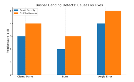 Chart 4: Busbar Bending Defects — Causes vs Fixes
Five proven techniques to prevent copper busbar marking:
- Mark-free pads — Polyurethane or rubber bending pads spread clamp force across a large area instead of concentrating it on a sharp edge. They’re the single most effective upgrade for cosmetic-critical work.
- Protective films — Adhesive-backed PE or PI films applied to the bar before bending leave the underlying copper untouched. Remove the film after the final bend.
- Radiused clamps — Sharp clamp edges leave straight-line impressions. Specify clamp tooling with a small chamfer or radius at every contact point.
- Deburr before bending — Burrs from prior shearing or punching create micro-pressure points that drag across tooling surfaces, leaving long parallel scratches. Always deburr before the bar enters the bending machine.
- Inspect under angled light — Surface marks are easiest to detect with raking light from a flashlight at a low angle, not overhead lighting. Build this into the QA station setup.
A short defect-vs-fix reference for copper busbar marking:
| Defect | Likely Cause | Fix |
|---|---|---|
| Long parallel scratches | Burr drag during clamping | Deburr edges before bending |
| Localized clamp impression | Sharp-edge clamp | Switch to radiused or padded clamp |
| Wavy surface scuffs | Dry tooling at high speed | Apply drawing lubricant |
| Cracks at outer radius | R below R_min | Increase die radius or anneal bar |
| Inside-radius wrinkles | No wiper support | Add wiper pad or reduce thickness/width ratio |
Controlling Springback in Copper Busbar Bending: Overbend Strategy & Angle Accuracy
Springback is the partial elastic recovery that happens after a copper busbar is released from the bending tool. The bar relaxes back toward its original shape by a few degrees — and if that recovery isn’t compensated for, every bend will fall short of its target angle. For hard-temper copper, springback can exceed 5–8 degrees on a 90-degree bend. For annealed copper, it drops to 1–3 degrees but never disappears entirely.
Three techniques to control springback in copper busbar bending:
- Overbend strategy — Bend the bar slightly past the target angle. The bar then relaxes to the correct final angle once force is released. The overbend amount is determined by trial bends on coupons from the same material lot.
- Angle-measurement systems — Modern CNC copper busbar bending machines include real-time angle sensors that measure the bar mid-bend and auto-adjust ram travel. Teach-and-learn systems store the springback offset for each material/thickness combination, eliminating manual compensation after the first article.
- Servo-driven backgauges — Repeatable angle accuracy depends on repeatable material positioning. Servo backgauges position the bar within ±0.05 mm bend-after-bend, while manual stops drift over a production run and introduce angle variation independent of springback.
For laminated or thick copper busbars, an additional technique is incremental bending — applying the total bend in two or three small strokes rather than one large stroke. This reduces peak strain, lowers springback magnitude, and extends die life on tight-radius work.
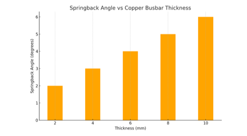
Chart 3: Springback Angle vs Thickness
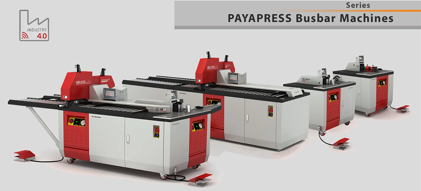
Choosing a Copper Busbar Bending Machine: Hydraulic, CNC, and Hybrid Bar Benders Compared
The right copper busbar bending machine depends on production volume, tolerance requirements, and how often bend programs change. Three machine categories dominate the market today:
1. Hydraulic copper busbar bending machine Manual or semi-automatic. Uses hydraulic pressure to drive the bend tool. Low capital cost, high force capacity, ideal for repair shops and low-volume custom work. Operator handles material positioning and angle compensation. Best for shops bending fewer than 50 busbars per shift.
2. CNC copper busbar bending machine Fully programmable. Servo-driven ram, backgauge, and angle compensation. Stores bend sequences, springback offsets, and tool libraries. Achieves angle accuracy to ±0.1° on a calibrated machine and delivers consistent results across thousands of parts. Best for switchgear OEMs, EV battery pack producers, and any shop running repeat orders.
3. Hybrid copper bar bender (3-in-1 busbar processing machine) Combines bending, punching, and cutting on a single platform. The bar moves through three stations without re-fixturing, eliminating the alignment errors that occur when bars are transferred between standalone machines. Hybrid copper bar benders are the fastest-growing category in busbar fabrication because they cut floor space, reduce handling time, and improve end-to-end accuracy — particularly for high-mix, medium-volume electrical panel production.
Quick comparison:
| Machine Type | Precision | Throughput | Best For |
|---|---|---|---|
| Hydraulic | Medium (±1°) | Low | Job shops, repair work |
| CNC | Excellent (±0.1°) | High | OEM production, repeat orders |
| Hybrid 3-in-1 | Excellent (±0.1°) | Very High | Integrated punch-bend-cut workflows |
When evaluating a copper busbar bending machine, look beyond tonnage and bed length. The decisive specs are angle-measurement system, backgauge resolution, tool changeover time, and whether the controller supports DXF import for offline programming.
Setup & Changeover: Fast, Consistent Copper Busbar Bending
Quick-Change Dies
Quick-change dies and repeatable zeroing reduce downtime and increase consistency in production runs.
Offline Programming vs SOPs
CNC machines support offline programming for greater precision. Hydraulic/manual machines rely on detailed SOPs.
First-Article Approval
First-article approval ensures early detection of errors before scaling production.
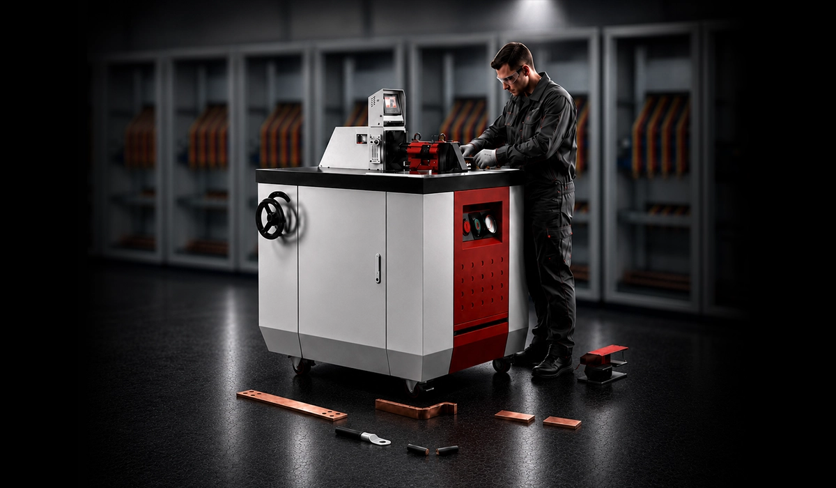
Safety & Ergonomics for Copper Busbar Bending Operations
Interlocks & Controls
Safety systems include interlocks, light curtains, and two-hand/foot controls to protect operators.
Handling Risk Reduction
Lifting aids, Personal Protective Equipment, and safe handling reduce ergonomic risks.
Maintenance & Total Cost of Ownership for Copper Busbar Bending Machines
Preventive Maintenance
Scheduled checks (daily, weekly, annual) extend equipment life and sustain bend accuracy.
Spare-Parts Strategy
Maintain stock of key spares like pads, sensors, encoders, and dies to minimize downtime.
Training & Documentation
Train operators and document procedures to ensure accuracy over time.
Copper Busbar Bending Buyer & Tooling Checklist
When planning or purchasing, consider:
1. Material and thickness/width (Cu/Al)
2. Minimum bend radius (R_min)
3. Angle tolerance & repeatability
4. Mark-free requirements
5. Hole/slot plan vs bend lines
6. Die set & quick-change
7. Angle measurement system
8. Backgauge/servo positioning
9. QA plan & sampling
10. Maintenance & spares
11. Safety & guarding features
Conclusion: Mastering Copper Busbar Bending for Reliable Electrical Performance
Accurate copper busbar bending is what separates a switchgear assembly that passes inspection on the first article from one that gets rejected at the QA gate. By respecting minimum bend radius (1–2× thickness), annealing between aggressive bends, controlling springback with overbend and angle sensors, and protecting surfaces with mark-free tooling, fabricators can eliminate the three most common copper busbar defects: cracks, marks, and angle drift.
Whether you’re running a single hydraulic press for one-off battery busbars or a fleet of CNC and hybrid 3-in-1 copper bar benders for a switchgear production line, the principles in this guide apply equally. Specify the right machine for your volume, validate the first article on real material coupons, and lock in QA checkpoints across the run.
For help specifying a copper busbar bending machine for your application — including hydraulic, CNC, and hybrid 3-in-1 configurations — download our RFQ checklist or request a consultation.