








If you’d rather listen than read, feel free to play the audio file below for the rest of this article.
What Programming Actually Means on a Busbar Machine
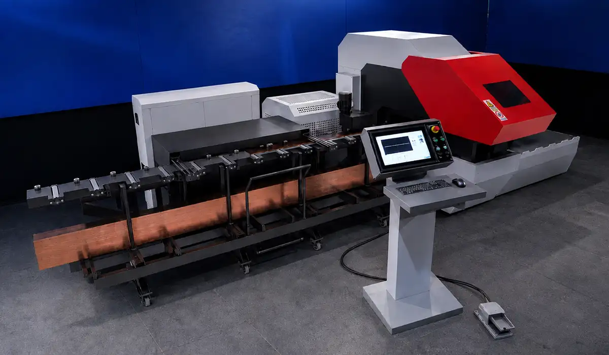
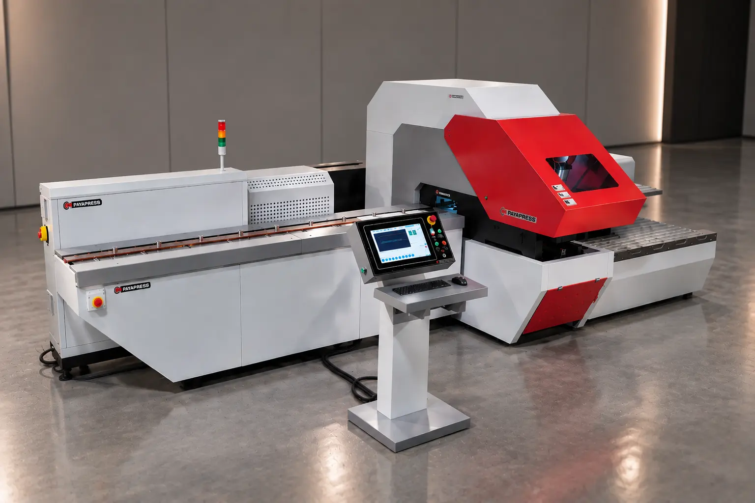
Learning how to program a CNC busbar machine means learning data discipline, not code syntax: correct setup data gives a correct part on the first bar. The control layer is a PLC or CNC platform, commonly Siemens, Fanuc or Beckhoff, with an HMI touch panel on top. Ladder logic or function blocks run underneath, and the operator never edits them. CNC busbar machine programming therefore splits into two routes. You either type parameters on the panel, or you import a drawing and let software convert it.
| Criterion | Parametric HMI entry | Drawing import (CAD/CAM) |
|---|---|---|
| Best fit | Flat or single-bend parts in repeat batches | Multi-bend parts and parts from a 3D panel model |
| Developed length | You calculate it | Software calculates it from the model |
| Main error source | Retyping numbers off the drawing | Dirty or unlayered DXF files |
| Pre-cut check | Dry run | On-screen simulation plus dry run |
| Choose it when | Parts have one bend or fewer and no 3D model exists | Parts carry two or more bends or arrive as 3D models |
Parametric entry on the HMI
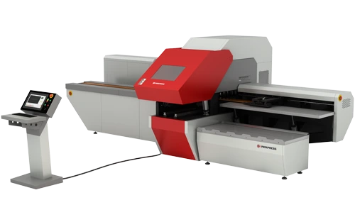
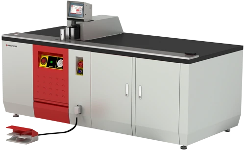
Parametric entry turns one typing session into repeatable batches, because the stored busbar machine program recalls every value by name. You enter bar width, thickness, material, temper and cut length. Then add hole X and Y coordinates, hole size or die number, and each bend angle and position. The control saves these under a name or number, so you type once per part, not once per bar. Pick absolute or incremental positioning and keep it; mixing them mid-program causes drift. Simpler programmable stoppers hold around 20 stored positions. Full CNC lines use servo drives with ball-screw length measurement and store complete part programs. Once you confirm parameters and tooling, the foot pedal starts the cycle.
Importing a drawing instead of typing
Importing a drawing removes the biggest shop error source, retyping numbers off paper, by generating machine code from geometry. For DXF import, the software accepts DXF and DWG for 2D, plus STEP and IGES for 3D models from AutoCAD, SolidWorks or EPLAN. Busbar CAD/CAM software then calculates punch, shear and bend positions without manual transcription. It also plays the sequence on screen, exposing collisions and impossible tool orders before copper moves. Busbar nesting software arranges parts across standard 6 m (about 20 ft) stock and tracks offcuts. Software vendors report utilization above 98% with good nesting. Still, a messy DXF with poor layers needs manual cleanup.
A program can only use what the machine physically carries, from servo axes to punch stations. Before you plan your first programs, see which CNC busbar machine equipment a complete line needs.
What the Drawing Must Tell You Before You Program
Run this checklist before you touch the panel, because scrapped bars usually trace back to one item someone assumed instead of confirmed. Any CNC busbar processing machine executes wrong data perfectly.
Material and temper come first. C110 copper behaves differently from 6101 or 6063 aluminum, and soft-annealed stock differs from hard-drawn. Temper shifts springback and minimum radius together, so record it in the program.
Next, check the cross-section. Confirm width and thickness against the machine’s rated capacity.
Then read the hole pattern. You need diameter and shape, coordinates, and the datum behind them. Round dies commonly run M6 to M20, while oblong and rectangular dies are optional extras.
After that, sort the dimensions. Mark which lengths are finished dimensions and which one is the blank. That distinction separates a good part from scrap, and Step 2 covers it.
Tolerances matter too. Hole position and angle tolerances decide how much first-article measurement you need.
Finally, check the clamp no-go zone. Every machine has an area near the bar ends where the clamp sits and no hole can go. Check the part against it now.
If any item is missing, call engineering instead of guessing.
For a clearer and more complete explanation, this page goes into far more depth than we can cover in a short text.
Programming the Job Step by Step
Here is how to program a CNC busbar machine in four steps. The order matters: jump to hole coordinates before you set the datum, and you lose the bar.
Step 1: Set the reference edge and zero point
One confirmed datum keeps every hole in the busbar machine program where the drawing puts it. Each coordinate measures from one physical feature, and the machine needs to know which. Usually that means the leading bar end against the stop, plus one long edge. Watch for the mirror trap. A symmetric-looking bar programmed from the wrong edge looks fine until it meets the panel with every hole reversed. Use a laser center finder or optical reference where fitted. Either way, confirm zero on the first bar instead of trusting the last job’s setting. Never switch datums mid-program to fix a problem; re-dimension from one datum.
Step 2: Enter the developed length, not the finished length
Entering the developed length lands bent parts on size, because the machine cuts a flat blank longer than the finished legs. It equals the straight legs plus one bend allowance per bend: BA = (π/180) × angle × (R + K × t). Rules of thumb: K ≈ 0.33 when R/t is below 2, 0.35 for annealed copper, 0.40 for quarter- or half-hard C110, and 0.5 above R/t 4. Example: a 10 mm bar, 10 mm inside radius, 90° bend and K = 0.33 gives BA ≈ 20.9 mm. With 200 mm and 150 mm straight legs, you cut 370.9 mm. Import-based systems calculate this from the 3D model.
Step 3: Assign punch stations and hole coordinates
Checking the tool table before you enter busbar punching coordinates stops a proven program from punching the wrong hole. The program calls a tool station, not a hole size, and the tool table links each station to its die. Swap a die without updating that table, and a perfect program punches the wrong diameter. Then check three rules of thumb. Hole diameter should at least equal bar thickness. Hole edge to bar edge should be at least one thickness, and two is safer. A hole center should sit at least 2.5 thicknesses plus the inside radius from a bend line, or forming distorts it. Order holes to cut carriage travel, and re-check the clamp no-go zone against the real coordinates.
Step 4: Program the bends, angles and springback
A logged springback offset turns one trial bend into repeatable angles for every later batch. In your busbar bending program, set the sequence first, because it decides whether you can still grip the last leg without hitting the frame. For flat bends in half-hard copper, the industry guide sets minimum bend radius at 1 × thickness up to 10 mm. It rises to 1.5 × to 25 mm and 2 × to 50 mm, while edgewise bends need 1.5–2 × bar width. Springback compensation corrects elastic recovery, which varies with temper and radius. Set each value by trial bend per material and temper, then log it. Expect roughly ±0.3° repeatability from servo CNC benders and ±0.5° from digital angle sensors.
Verifying the Program Before You Cut Copper
A program is finished only when a part off it measures right, and a five-minute check costs less than one scrapped bar. Treat verification as the last stage of how to program a CNC busbar machine, not a separate QA task.
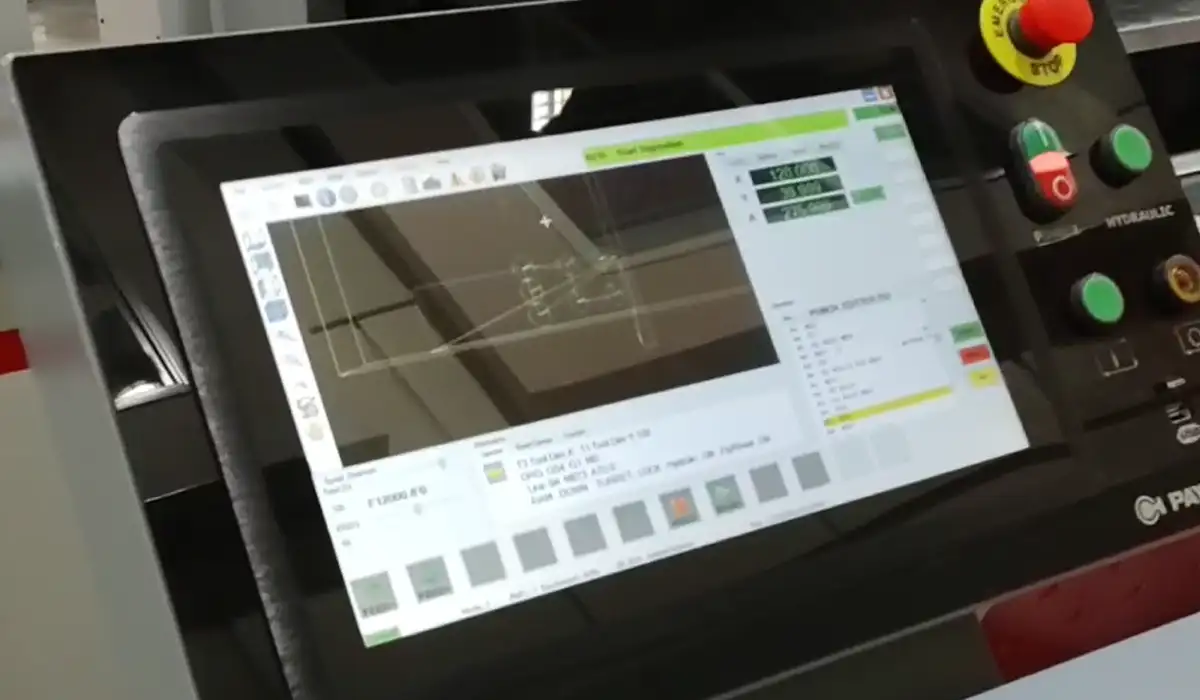
First, simulate. Where the software supports it, play the sequence on screen and read it for collisions, tool order and reachability.
Second, dry run. Cycle the program without material, or on a scrap offcut of the same section, to confirm travel, stops and tool calls.
Third, run a first article inspection. Produce one complete part and measure overall length, hole-center distances from the datum, hole diameters, bend angles and leg lengths.
Then read the results as diagnostics. A part short by the same amount everywhere points to developed length. A pattern that drifts progressively points to mixed absolute and incremental positioning. A mirrored pattern points to the datum.
Fourth, release. Run the batch only after the first article passes, and record the measured result against the program.
A dry run pays for itself the first time it catches anything.
Readers who want to understand the reasoning behind this will find this detailed article very useful.
Programming Mistakes That Cost Bars
CNC busbar machine programming errors repeat across shops, and each leaves a measurable symptom.
- Finished length instead of developed length. Symptom: every bent part is short by the same amount. Fix: enter the flat blank with bend allowance.
- Die changed, tool table not updated. Symptom: correct coordinates, wrong hole size. Fix: update the table at every die swap.
- Datum on the wrong edge or end. Symptom: a mirrored pattern that appears only at assembly. Fix: mark the datum on both drawing and bar.
- Absolute and incremental positioning mixed. Symptom: errors grow along the bar. Fix: use one positioning mode per program.
- Clamp no-go zone ignored. Symptom: the last hole becomes unreachable after every other operation. Fix: check coordinates against the zone before saving.
- Springback offset from another temper. Symptom: angles run consistently over or under target. Fix: store offsets per material and temper.
- Hole too close to a bend line. Symptom: the hole turns oval during forming. Fix: keep 2.5 thicknesses plus the inside radius.
- Proven program overwritten. Symptom: the next order for the old part won’t run. Fix: save every change as a new revision.
- First article skipped on a familiar part. Symptom: a full batch of scrap. Fix: verify every new program; this habit costs the most.
Not every bad part is a programming error; a worn die or a drifting axis leaves the same symptoms. Rule out the hardware first with a regular CNC busbar machine maintenance routine.
Saving, Naming and Reusing Programs
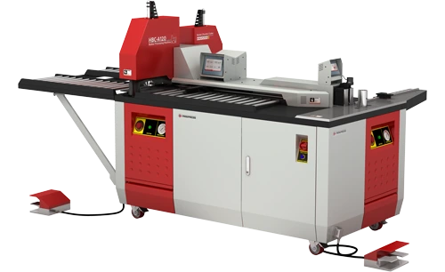
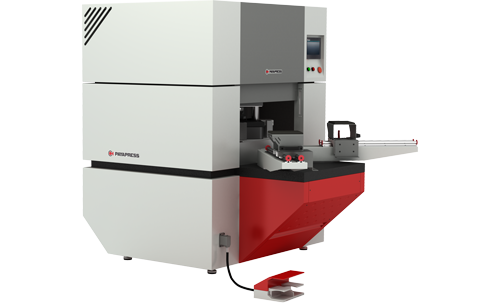
The return on CNC comes from the second run of a part, not the first, and it exists only if you can find the program again. Name every program by part number plus revision, never “job1” or a customer’s first name. Store material and temper with it, plus tooling and station assignment. Add the springback offset proven on the first article and the date of the last good run. That record makes programming a busbar machine a one-time effort per part. When a part changes, create a new program instead of editing the old one. Machine memory is not a backup, so export the program library to a network location on a schedule. On lines linked to MES, ERP or a warehouse control system, programs and job orders arrive from the production schedule. The naming discipline above keeps that link working.
Every reused program cuts setup time and scrap, and that is where the payback on a CNC line comes from. To put real numbers on it for your shop, work through our guide to CNC busbar machine ROI.
Conclusion about How to Program a CNC Busbar Machine
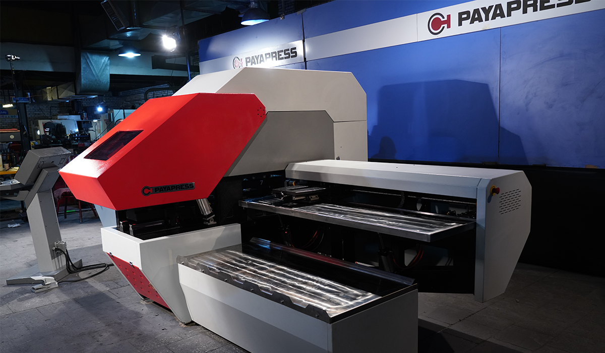
Knowing how to program a CNC busbar machine comes down to one repeatable order: datum, developed length, tooling, bends, then a measured first article. The shops that get real value from CNC treat every program as a controlled document. If you sell to panel builders and switchgear makers, become a PAYAPRESS representative and bring that discipline to your market.



Rate this article
Choose a rating from 1 to 5 stars.
No ratings yet