IEC 62271-200 is the IEC standard covering AC metal-enclosed switchgear and controlgear for rated voltages above 1 kV and up to 52 kV. It replaced IEC 60298 and aligns with IEC 62271-1 to prioritize personnel safety and service continuity over cabinet terminology.
For your convenience, if you prefer listening, you can listen to the rest of this article via the audio file below:
Medium voltage (MV) metal-enclosed switchgear
IEC 62271-200 applies to medium voltage (MV) metal-enclosed switchgear and controlgear — specifically AC systems rated above 1 kV and up to and including 52 kV. This covers the vast majority of primary distribution switchgear used in industrial facilities, data centers, utility substations, and infrastructure projects worldwide.
The term “medium voltage metal-enclosed switchgear” is used throughout this guide to refer to the equipment class governed by IEC 62271-200. Equipment below 1 kV falls outside this standard’s scope (see IEC 61439 series for low voltage assemblies). Equipment above 52 kV is governed by separate IEC 62271 parts covering high-voltage switchgear.
Key point for specifiers: IEC 62271-200 does not prescribe a specific enclosure layout or cabinet construction style. Instead, it defines performance requirements — for safety, insulation, arc resistance, and service continuity — that the medium voltage switchgear assembly must demonstrate through type testing. The manufacturer’s design is their responsibility; compliance with the standard is what you are buying.
For further reading on Impact of IEC, UL, and CE Standards on Switchgear and Busbars, see our related article here.
What’s IEC 62271-200 Covers
- Field Of Application: AC Metal clad switchgear and control gear, indoor or outdoor. replaces current IEC 60298 and aligns with IEC 62271‑1.
- Typical Format: Ratings; Design & Construction; Type Tests; Routine tests.
- Key concept: Put people’s safety and service continuity first, rather than cabinet makeup.
Metal‑enclosed vs Metal‑clad
• Metal‑enclosed is the general family: live parts are behind an earthed metal enclosure.
• Old style terms like “metal‑clad/compartmented” are now less important. IEC uses LSC (Loss of Service Continuity) and Partition Class (PM/PI) to describe safety and access.
For more information, read this.
Internal Arc Classification (IAC) Explained
• Goal: protect PEOPLE during an internal arc fault (very hot gas, high pressure, particles).
• Test: create a 3‑phase arc with an ignition wire. Vents and ducts must control pressure and gas.
• Pass criteria (all five must be OK): 1) doors/covers stay closed; 2) no dangerous fragments; 3) no holes on accessible sides up to 2 m; 4) indicators do not ignite (note: 1‑second rule in 2025 edition); 5) earthing stays effective.
• Marking example: IAC A FLR 31.5 kA 1 s (accessibility type A; protected at Front, Lateral, Rear; arc current and duration).
IAC AFLR Notation and Sides
• IAC = Internal Arc Classification.
• A or B = accessibility (A for authorized locations; B for public).
• Sides: F = front, L = lateral, R = rear. Show all sides that passed the test.
• Current I and time t must appear on the nameplate.

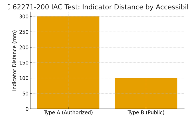
Accessibility Types A vs B
• Type A (authorized personnel): test indicators at 300 mm distance.
• Type B (public access): indicators at 100 mm.
• Type C (out of reach) is handled in other IEC parts and not used for typical metal‑enclosed MV switchgear.
For comprehensive insights into IP55 vs NEMA 12: What’s the Difference?, check out this article.
LSC Categories and Service Continuity
• LSC shows how much of the system can stay in service when you open a compartment for work.
• LSC1: lowest continuity; opening one accessible part requires isolating the whole panel/section.
• LSC2A: you can open a compartment while busbar and adjacent panels stay energized; incoming cable is isolated.
• LSC2B: highest continuity; when you open a compartment, the incoming cable, busbar, and adjacent panels can stay energized. Needs partitions and proper isolating distances.
Partition Class PM vs PI
• PM (Partitions of Metal): metal shutters/partitions between live parts and the open compartment. Best for personnel safety and earthing continuity; also reduces electric‑field exposure.
• PI (Partitions of Insulating material): discontinuity of metal is covered by insulating material. Acceptable in some cases, but safety philosophy is different from PM.
• LSC choice and PM/PI are linked: many utilities and data centers prefer LSC2B, PM.
Ratings You Must Specify
• Rated voltage Ur and insulation levels: select Up (lightning impulse) and Ud (power‑frequency withstand) using IEC 62271‑1 tables, per your system overvoltage level.
• Short‑time withstand current (Ik, e.g., 25 kA 3 s): thermal and dynamic endurance of main/earth circuits.
• IAC current and duration: e.g., 31.5 kA 1 s, sides AFLR, type A or B.
• Nameplate fields: IAC code, Ur, Ik (time), frequency, IP/IK, mass, serial, manual references.
Type Tests vs Routine Verification
• Type Tests (on a prototype): internal arc test, dielectric withstand, switching capabilities (breaker and earthing switch tested inside the panel), temperature rise (where applicable), mechanical operations, interlocks, degrees of protection.
• Routine Tests (on every delivered unit): high‑potential/insulation checks per rating, control circuits, interlocks, mechanical function, wiring/marking, routine verification records. Keep reports for handover.
Marking, Labeling, and Documents (EU/UK focus)
• Show IAC label with accessibility, sides, current, time.
• Provide operation/maintenance manual, routine test records, wiring diagrams, nameplate data, IP/IK references.
• Many owners request a compliance checklist attached to the FAT dossier.
Want to dive deeper? Our article on AS/NZS 61439 vs IEC 61439 – Practical Guide for Low Voltage Assemblies explains it thoroughly.
Arc Detection and Mitigation Options
• Faster clearing reduces damage but does not replace IAC testing.
• Options: optical arc relays, high‑speed shorting devices, pressure relief ducts/exhaust routing, fast earthing switches, zone‑selective interlocking.
• Plan duct orientation to move hot gas away from the operator corridor.
For further details, please read this article.
IEC 62271-200 vs IEEE C37.20.7: full comparison for global projects
Both IEC 62271-200 and IEEE C37.20.7 address arc-resistant behavior in metal-enclosed medium voltage switchgear, but they use different test methodologies, accessibility classifications, and marking conventions. Ratings are not directly interchangeable — never assume a unit tested under one standard satisfies the other without verification.
| Comparison point | IEC 62271-200 | IEEE C37.20.7 |
|---|---|---|
| Governing body | IEC (International Electrotechnical Commission) | IEEE (Institute of Electrical and Electronics Engineers) |
| Primary market | Europe, Middle East, Asia, international projects | North America (US and Canada) |
| Voltage scope | >1 kV up to and including 52 kV | Up to 38 kV (class E2) |
| Arc test ignition method | 3-phase arc initiated with an ignition wire | 3-phase arc initiated with a copper wire fuse |
| Test current & duration | Specified by purchaser (e.g. 31.5 kA, 1 s); stated on nameplate | Typically tested at 40 kA or 50 kA for 0.5 s or 1 s |
| Accessibility classification | Type A (authorized, 300 mm) / Type B (public, 100 mm) | Type 1 (accessible to authorized personnel) / Type 2 (accessible to public) — measured at 914 mm (36 in) |
| Pass criteria — indicators | Indicators must not ignite within 1 second (IEC 62271-200:2021) | Indicators must not ignite within 2 seconds |
| Protected sides notation | F (front), L (lateral), R (rear) — e.g. AFLR | Front, sides, rear tested; no per-side letter notation on label |
| Nameplate marking example | IAC A FLR 31.5 kA 1 s | “Arc resistant, Type 1, 40 kA, 1 s” |
| Service continuity concept | Formal LSC categories (LSC1, LSC2A, LSC2B) | Not formally defined; addressed through design intent |
| Partition class | PM (metal) / PI (insulating) — formally specified | Not classified under equivalent terminology |
| Pressure relief | Duct must route gas away from accessible sides; performance verified in arc test | Similar requirement; duct routing guidance is less prescriptive in the standard itself |
| Type test evidence | Full test report from accredited laboratory required; report must reference the edition | Full test report required; KEMA, CESI, Intertek, and similar labs accepted |
For dual-market projects (IEC and IEEE both required):
- Specify both standards explicitly in the procurement document: “Equipment shall comply with IEC 62271-200:2021 and IEEE C37.20.7. Where requirements differ, the more stringent shall apply.”
- Require separate type-test certificates for each standard — a single test campaign rarely satisfies both simultaneously due to differences in indicator distance and arc ignition method.
- Confirm the arc current and duration are tested at the same values for both certificates; test campaigns are often conducted at different currents.
- Verify the indicator ignition pass time explicitly — IEEE allows 2 seconds, IEC 62271-200:2021 requires 1 second. A unit with only an IEEE certificate may not satisfy the IEC criterion.
- Review nameplate marking conventions with the end client before finalizing — operators in IEC markets will expect AFLR notation; IEEE-trained operators will not recognize it without explanation.