




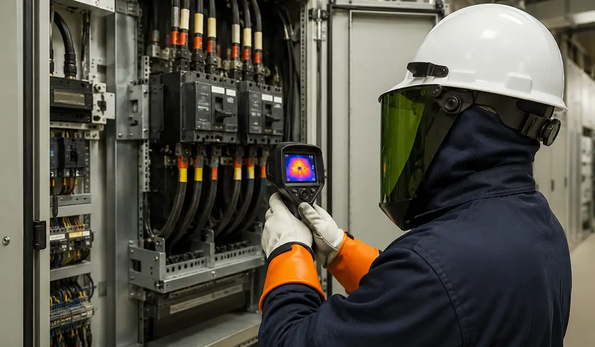





How to Read Arc Flash Labels: A Field-by-Field Walkthrough
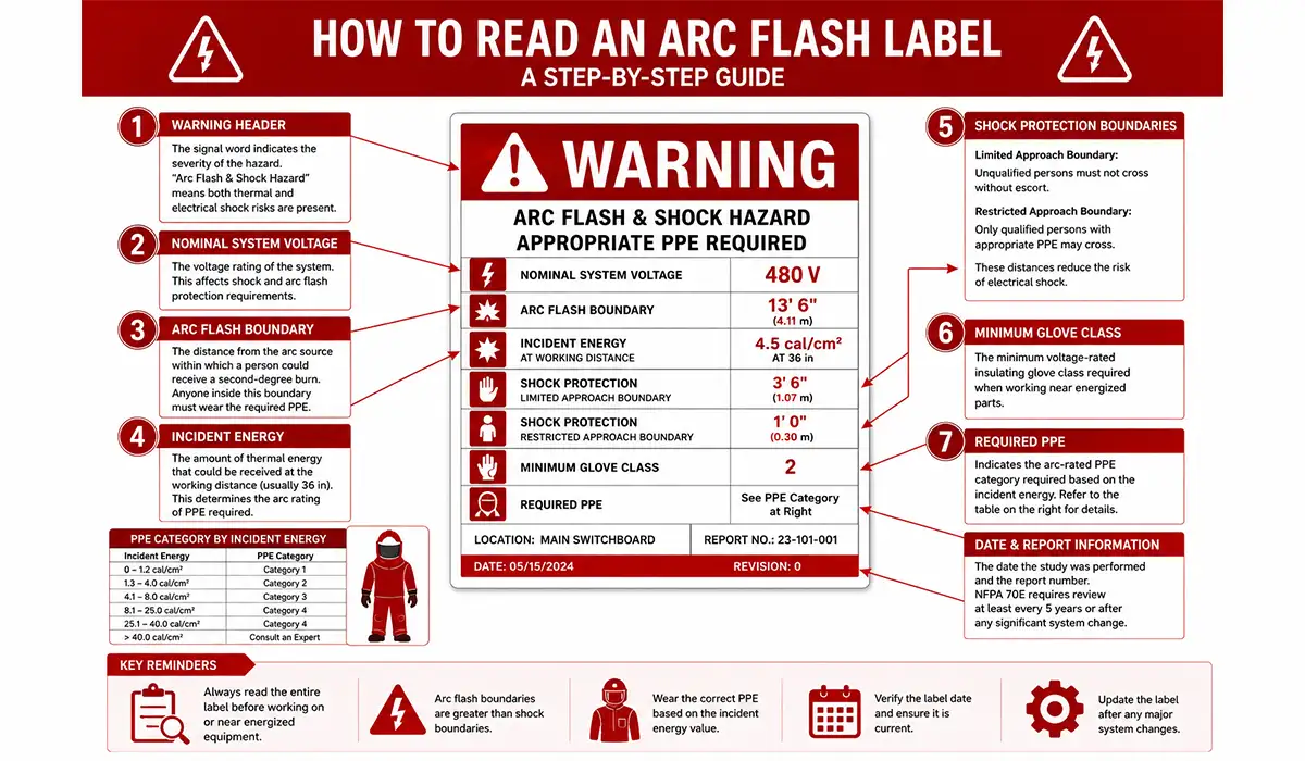
Most arc flash labels share one layout. Read them top to bottom:
- a signal-word header
- an arc flash protection block
- a shock protection block
- an identification strip with the equipment name, study reference and date
The fields below appear on labels produced from an incident energy analysis. A PPE category label replaces the incident energy line with a category number.
What an Arc Flash Label Is — and What It Is Not
An arc flash label is a hazard marking on electrical equipment. It tells a qualified person how severe an arc flash could be at that spot and what protection is needed to work there while energized. It summarizes the arc flash risk assessment; it is not the assessment itself.
The label also doesn’t make energized work acceptable. NFPA 70E still expects an electrically safe work condition unless energized work is justified. Arc flash injuries are uncommon but severe, and they happen in milliseconds, so read the label before the door opens.
Signal Word on an Arc Flash Label: WARNING or DANGER?
The header uses an ANSI Z535.4 signal word:
- WARNING (orange) marks a hazard that could cause death or serious injury.
- DANGER (red) marks one that will.
NFPA 70E sets no threshold between the two, so the choice belongs to the owner’s labeling policy. A common convention is DANGER where incident energy exceeds 40 cal/cm², where no PPE category applies, or above 600 V, and WARNING everywhere else. The header usually reads “Arc Flash and Shock Hazard,” because the label covers both hazards.
Nominal System Voltage: The First Number to Check
The nominal voltage (for example, 480 V or 208Y/120 V) decides which shock boundaries, glove class and test instruments apply. Both NFPA 70E 130.5(H) and the 2026 NEC require it on the label. If it doesn’t match what you expect for that equipment, stop: the label may belong to another study or to replaced equipment.
Arc Flash Boundary: Where Incident Energy Drops to 1.2 cal/cm²
The arc flash boundary is the distance from the arc source at which incident energy falls to 1.2 cal/cm². That is the level associated with the onset of a second-degree burn on bare skin. Anyone inside the boundary while parts are exposed and energized needs arc-rated PPE.
Some labels give separate boundaries for the line side and load side of a main device. The line side is cleared by the upstream device and can carry far more energy.
Incident Energy and Working Distance: Always Read Them Together
Incident energy, in cal/cm², is the heat expected at the worker’s face and chest at the stated working distance. The two values belong together: the same arc delivers more energy closer in, so the number is valid only at the printed distance.
IEEE 1584 uses these typical working distances:
- 18 in (455 mm) for low-voltage panelboards and MCCs
- 24 in (610 mm) for low-voltage switchgear
- 36 in (910 mm) for medium-voltage switchgear
If your task puts your body closer than the printed distance, the label understates your exposure.
Shock Boundaries on the Label: Limited and Restricted Approach
- Limited approach boundary: unqualified persons may cross it only while continuously escorted by a qualified person who has warned them of the hazards.
- Restricted approach boundary: only qualified persons with shock protection, such as rubber insulating gloves, may cross it.
Shock and arc flash boundaries are calculated separately. At low incident energy, the arc flash boundary can be shorter than the limited approach boundary; at high energy, it can be many times longer. Observe each boundary for the hazard it covers.
Glove Class and PPE: Two Different Hazards on One Label
Glove class is shock protection. It is chosen from the voltage and tells you which rubber insulating gloves to wear inside the restricted approach boundary. For example, Class 00 is rated for up to 500 V ac and Class 0 for up to 1,000 V ac.
The PPE line is arc flash protection. It comes from the incident energy or the PPE category tables and tells you which arc-rated clothing and face and head protection to wear inside the arc flash boundary.
The two lines are independent, and energized work on exposed parts needs both.
How Is Arc Rating Derived? NFPA 70E, ATPV and EBT
The arc rating on your clothing is the number you compare with the label. NFPA 70E defines arc rating as a material’s performance when exposed to an electric arc, expressed in cal/cm² and derived from one of two test values:
- ATPV (arc thermal performance value): the incident energy at which there is a 50% probability that heat through the fabric causes the onset of a second-degree burn, based on the Stoll curve.
- EBT (energy of breakopen threshold): the incident energy at which there is a 50% probability that the fabric breaks open, leaving a hole of at least 1.6 cm² (0.5 in²).
Both values come from testing to ASTM F1959/F1959M. The lower of the two becomes the garment’s arc rating, which is printed on the garment label under ASTM F1506.
To use it, compare it with the label. The arc rating must be at least the incident energy printed at the working distance, or at least the minimum arc rating the label states.
For PPE category labels, the minimum arc ratings are:
- Category 1: 4 cal/cm²
- Category 2: 8 cal/cm²
- Category 3: 25 cal/cm²
- Category 4: 40 cal/cm²
A layered clothing system has its own tested rating; the ratings of individual layers don’t simply add together.
Equipment ID, Study Date and Revision: Is This Label Still Valid?
The identification strip ties the label to its source: equipment name, report number, revision and date. NFPA 70E requires the data behind the label to be reviewed at intervals of no more than five years, and the label updated whenever a change makes it inaccurate. Where the 2026 NEC is adopted, the marking must show the date the assessment was completed, not just the date the label was printed.
Treat a label as unverified if:
- its study date is more than five years old, or
- it names equipment that has since been replaced.
Which Arc Flash Label Applies? Four Questions That Decide It
To select which arc flash warning label applies, work through four questions in order.
- Is the equipment likely to be examined, adjusted, serviced or maintained while energized, in other than a dwelling unit?
If yes, both NFPA 70E and the NEC apply. Testing for absence of voltage is itself done while the equipment is treated as energized, so “we always de-energize” rarely removes the need for a label. - Which NEC edition does your jurisdiction enforce?
- 2023 NEC: a general arc flash warning on the equipment. Service and feeder-supplied equipment rated 1,000 A or more also needs a detailed, dated label.
- 2026 NEC: a permanent marking on service and feeder-supplied equipment, with no ampere threshold. It must show nominal voltage, arc flash boundary, incident energy or minimum PPE, and the date the assessment was completed.
- What does NFPA 70E 130.5(H) require?
A label with the nominal voltage, the arc flash boundary, and one PPE basis. The PPE basis is one of:- incident energy with its working distance, or the PPE category (never both)
- the minimum arc rating of clothing
- a site-specific PPE level
- Does an exception apply? See the exceptions section below.
The answer usually points to one of these label types:
| Label type | What it shows | Typical use |
|---|---|---|
| General warning label | Hazard warning only, no values | 2023 NEC minimum; not enough for NFPA 70E energized work |
| Incident energy label | Voltage, boundary, cal/cm² at working distance, shock data | Equipment covered by an incident energy analysis |
| PPE category label | Voltage, boundary, PPE category 1–4, shock data | Equipment inside the NFPA 70E table limits |
| High-energy DANGER label | Voltage, boundary, energy above 40 cal/cm² or “no PPE category” | Energized work avoided; most programs require de-energizing |
| Documented-data label | Hazard warning, with the data held in a readily available system | Supervised industrial installations (Exception No. 2) |
Worked Example: Which Label Goes on a 100 A Fused Switch?
Take a 100 A, 480 V fused disconnect in a factory. It is fed from a feeder and opened now and then for energized troubleshooting.
- 2023 NEC: at 100 A it is below the 1,000 A threshold, so the general warning is the NEC minimum.
- 2026 NEC: it is feeder-supplied equipment likely to be worked on energized, so it needs the full marking, including the assessment date.
- NFPA 70E: it needs a full 130.5(H) label, whatever its ampere rating.
Two engineering points set the numbers on that label:
- The fuses protect only the load side. The line-side terminals are cleared by the upstream device, so the label should reflect whichever side carries more energy, which is usually the line side.
- Current-limiting fuses aren’t always fast. They clear high fault currents very quickly, but at lower arcing currents they can take much longer. The incident energy must therefore come from the study at that location, not from the fuse rating.
The PPE category method works only if the available fault current and clearing time at the switch fall inside the table limits for that equipment type.
Arc Flash Exception Labels: What NFPA 70E’s Exceptions Really Allow
There is no standard product called an “arc flash exception label.” The term usually refers to the two exceptions in NFPA 70E 130.5(H):
- Exception No. 1: labels applied before the current edition took effect remain acceptable if they met the edition in force at the time, unless system changes have made them inaccurate.
- Exception No. 2: in supervised industrial installations where only qualified persons monitor and service the system, the voltage, boundary and PPE data may be documented in a readily available system instead of printed on the label. QR-code and database label programs rely on this exception. The equipment still carries a hazard warning.
Neither exception lets you skip the risk assessment.
The old IEEE 1584 “125 kVA exception” for equipment below 240 V is also gone. The 2018 edition replaced it with a statement that sustained arcs are possible but less likely at 240 V or less when available short-circuit current is below 2,000 A. That is guidance for the engineer doing the calculation, not a labeling exemption.
Arc Flash Labeling: NFPA 70E, IEEE 1584 and the NEC Each Do One Job
Arc flash labeling draws on three documents, each answering a different question:
- NFPA 70E says what a label must tell workers and who owns it.
- IEEE 1584 supplies the calculation behind the incident energy and the boundary.
- The NEC decides which equipment must be marked at installation.
(Keep the table and change two cells: NFPA 70E “Enforced By” becomes “Employers; OSHA uses it as the consensus benchmark,” and the NEC row becomes “AHJ, where adopted.”)
A generic NEC warning is not the same as a calculated NFPA 70E label. For the clause-by-clause detail, see our guide to arc flash label requirements and EC&M on why NFPA 70E contains no installation requirements. (The EC&M link is the existing one, re-anchored.) The wider picture is in our switchgear and busbar standards overview.
| Framework | Scope | Applies To | Enforced By |
|---|---|---|---|
| NFPA 70E | Work practices, PPE, risk assessment | Employers and workers | OSHA influence |
| IEEE 1584 | Arc flash calculations | Study engineers | Referenced practice |
| NEC 110.16 | Equipment warning labels | Installers and owners | AHJ |
NEC 110.16 and Your Label: 2023 Code vs 2026 Code
The NEC edition your state enforces changes what the label must show.
| 2023 NEC | 2026 NEC | |
|---|---|---|
| Section title | Arc-Flash Hazard Warning | Arc-Flash Hazard Marking |
| What gets marked | General warning on equipment likely to be worked on energized (non-dwelling). Detailed label on service and feeder-supplied equipment rated 1,000 A or more. | Permanent marking on service and feeder-supplied equipment likely to be worked on energized (non-dwelling). No ampere threshold. |
| Required content | Detailed label per applicable industry practice, plus the date the label was applied | Nominal voltage, arc flash boundary, incident energy or minimum PPE, and the date the assessment was completed |
| Durability and visibility | 110.21(B); clearly visible before work | Same |
Both editions give switchboards, switchgear, enclosed panelboards, industrial control panels, meter socket enclosures and motor control centers as examples. Because the 2026 marking needs study results and an assessment date, a generic sticker can’t satisfy it.
- 2026 changes in detail: EC&M’s summary of the 2026 changes. (This replaces the 2024 Schneider blog link, which predates the 2026 code.)
- Industrial control panels: see our UL 508A compliance guide.
NFPA 70E 130.5(H): The Data Behind Every Arc Flash Label
NFPA 70E 130.5(H) covers equipment such as switchboards, panelboards, industrial control panels, meter socket enclosures and motor control centers that are likely to be worked on while energized. The label must show:
- the nominal system voltage
- the arc flash boundary
- at least one of the following:
- available incident energy with its working distance, or the PPE category (not both)
- the minimum arc rating of clothing
- a site-specific level of PPE
The 2024 edition also requires labels durable enough for their environment. The method and data behind the label must be documented, and the equipment owner is responsible for documenting, installing and maintaining the label. For the full breakdown, see our arc flash label requirements guide.
Arc Flash Label Fields: Required, Alternative or Good Practice
| Information | Role | Source |
| Working distance | One of the PPE bases | IEEE 1584 study |
| PPE category | One of the PPE bases; never alongside incident energy | NFPA 70E tables |
| Minimum arc rating | One of the PPE bases | Study |
| Site-specific PPE level | One of the PPE bases | Owner’s program |
| Assessment date | Required under the 2026 NEC; good practice otherwise | Study report |
| Equipment ID, report number | Good practice | Site records |
| Shock boundaries, glove class | Good practice | NFPA 70E tables |
Available fault current and clearing time are study inputs. They drive the numbers but are not required label fields. Clearing times come from the protective devices; see our overcurrent protection methods guide.
Incident Energy Label vs PPE Category Label: How to Tell Them Apart
- An incident energy label prints a calculated value, for example 6.2 cal/cm² at 18 in. You choose PPE with an arc rating at least that high.
- A PPE category label prints a category from 1 to 4. The category comes from NFPA 70E tables that are valid only when the equipment’s available fault current, clearing time and working distance fall inside the table limits. You wear the PPE listed for that category.
NFPA 70E forbids putting both on one label, because two different bases invite the wrong choice. Most facilities with a full study now use incident energy labels, since the values are specific to each piece of equipment.
For how equipment class affects which tables apply, see panelboard vs switchboard vs switchgear.
Where the Numbers Come From: IEEE 1584-2018
IEEE 1584 is not a label standard. It is the calculation guide that turns system data into the incident energy and arc flash boundary printed on the label. The 2018 model uses:
- voltage
- available bolted fault current and arcing current
- protective device clearing time
- electrode gap and electrode configuration
- enclosure size
A label is only as current as those inputs. For an accessible overview, see the IEEE chapter’s introduction to the 2018 edition.
Why Old Arc Flash Labels and New Studies Disagree
Labels from IEEE 1584-2002 studies often differ from today’s results for three reasons:
- Electrode configuration. The 2018 model uses five configurations: VCB, VCBB, HCB, VOA and HOA. Horizontal electrodes direct more energy toward the worker.
- Enclosure size. Box dimensions now move the result up or down.
- The 125 kVA exemption is gone. The 2002 statement excluding equipment below 240 V unless fed by a 125 kVA or larger transformer was deleted.
If your labels predate the 2018 model, review them at the next study update. See ETAP’s summary of the 2018 model.
Arc Flash Label Design: ANSI Z535.4 Layout and Durable Materials
NFPA 70E and the NEC decide what the label says. ANSI Z535.4 guides how it looks: a signal-word panel, a safety symbol and a message panel.
The NEC adds field-marking rules in 110.21(B). The marking must:
- warn effectively
- be permanently affixed
- not be hand-written, except for values that vary
- withstand its environment
NFPA 70E 2024 adds its own durability requirement.
In practice, that means thermal-transfer printed polyester or vinyl on UL 969 label stock, resistant to UV and chemicals, and large enough for the values to stay legible. A 4 × 6 in label is a common size.
For layout guidance, see ANSI’s overview of Z535.4-2023. For outdoor or washdown locations, match the label material to the enclosure environment; our IP vs NEMA ratings guide explains those environments.
Label Format: What a Readable Arc Flash Label Looks Like
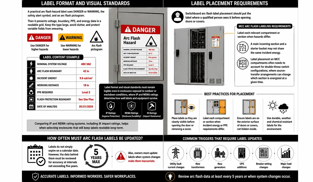
A readable label is laid out top to bottom:
- the signal word and safety alert symbol
- the arc flash block: boundary, incident energy or PPE category, and working distance
- the shock block: voltage, limited and restricted approach, and glove class
- the equipment ID, study reference and date
Use large type for the values workers act on, leave out marketing text, and print variable fields instead of writing them by hand.
Where the Arc Flash Label Goes
Place the label where a qualified person will see it before opening a door or removing a cover; both NEC editions require the marking to be clearly visible to qualified persons. On lineups, label every section or access point whose hazard differs.
Where a transfer arrangement lets a section be fed from more than one source, the study should label the worst credible case or document each configuration. See our double throw switch guide for how source transfer works.
When an Arc Flash Label Goes Stale
A label doesn’t expire on a set date, but its data does. Review the study at intervals of no more than five years, and sooner after any change that alters fault current or clearing time.
For a practical checklist, see Clark Dietz on confidence in arc flash labeling. New PV or battery systems also change fault contributions; see our solar power system wiring guide.
| Trigger | Review Action |
|---|---|
| Utility fault current change | Recalculate affected buses |
| Breaker setting change | Recheck downstream labels |
| New generator or UPS | Review source contribution |
| MCC expansion | Update section labels |
| IEEE 1584 model change | Evaluate recalculation |
Arc Flash Labeling by Equipment Type
Incident energy depends on available fault current, clearing time, enclosure size and working distance, so labels vary by equipment. A service switchboard usually sees more fault current than a branch panelboard. Still, low voltage doesn’t guarantee low energy: a slow upstream device can make a small panel dangerous. Label each task location from the study.
For how panel types differ, see our electrical panel types guide.
Switchboards and Switchgear: One Label per Hazard, Not per Lineup
Service switchboards and switchgear often carry the site’s highest incident energy. This is especially true on the line side of the main, which only the utility’s protection clears.
Label the main section and each distribution section separately where the values differ. A single worst-case label on a long lineup overstates the hazard at most sections and teaches workers to ignore it.
Arc-resistant switchgear limits exposure while doors are closed and latched. It is rated to IEEE C37.20.7 in North America and to the IEC 62271-200 internal arc classification elsewhere. Once a door is open, the label values apply.
For construction details, see our UL 891 switchboard guide and IEC 62271-200 internal arc guide. (Keep the first link; the second is moved here with an accurate rationale.) For the OSHA PDF, confirm its title, then re-anchor it descriptively or remove it.
Motor Control Centers: Label the Section and the Bucket
An MCC’s incoming section, horizontal bus and individual buckets can carry very different incident energy, because different protective devices clear faults at each point. A fault on the line side of a bucket breaker is cleared by the MCC main or the upstream feeder device, not by the bucket breaker. Label the access points separately wherever the study shows different values.
Panelboards at 208 V and 240 V: What Changed with IEEE 1584-2018
Older studies often skipped panelboards below 240 V fed by transformers under 125 kVA, relying on IEEE 1584-2002. The 2018 edition removed that exemption. It now says only that sustained arcs are possible but less likely at 240 V or less when available short-circuit current is below 2,000 A.
Treat that as a judgment call within the calculation, not a reason to leave a panel unlabeled. Where the 2026 NEC applies, feeder-supplied panelboards likely to be worked on energized need the full marking anyway. See e-Hazard’s analysis of the 125 kVA change.
Who Owns the Arc Flash Label?
NFPA 70E 130.5(H) is explicit: the equipment owner is responsible for documenting, installing and maintaining the label. The other roles around it:
- Study engineer: calculates the incident energy, boundaries and PPE, and documents the method and data.
- Manufacturer: may apply a factory marking, but can’t know site fault current or upstream clearing times.
- Installer: applies the NEC-required marking at installation, and should record any labeling decisions the owner makes at project closeout.
- Employer: trains workers to read the labels and act on them.
OSHA publishes no label format, but it treats NFPA 70E as the consensus benchmark for safe electrical work practices.
Conclusion: Read the Arc Flash Label, Then Question It
An arc flash label turns an engineering study into four facts a worker can act on:
- the voltage
- how close is too close
- how much energy to expect
- what to wear
Read every field. Check that the date and equipment match, and confirm the label type fits both the equipment and the code edition you work under. If any check fails, treat the label as unverified and go back to the study before the door opens.



Rate this article
Choose a rating from 1 to 5 stars.
No ratings yet