








In simple everyday language, The clearest analogy is the one the term came from: railway points. A single-throw switch is a level crossing barrier — the train goes or it stops. A double-throw switch is a set of points — the train continues either way, onto one track or the other, depending on which way the lever is thrown. “Throw” is literally the lever movement.
The industrial nuance comes from how many circuits it controls and how robust the mechanism is, especially when handling high currents or safety-critical roles. This guide walks you from basic definitions through wiring patterns and industrial use cases, explains how a DPDT switch works, shows where double throw safety switches fit, and highlights key standards like IEC 60947-3 you’ll see on many spec sheets.
For your convenience, if you prefer listening, you can listen to the rest of this article via the audio file below.
What Is a Double Throw Switch?
DPDT full form: Double Pole, Double Throw. Two independent circuits (poles), each able to connect to either of two outputs (throws). Six terminals — two commons and four throws — with one actuator moving both poles together.
The related acronyms: SPST (Single Pole, Single Throw), SPDT (Single Pole, Double Throw), DPST (Double Pole, Single Throw).
A double throw switch is a type of electromechanical device where each pole can connect to one of two outputs. Instead of just connecting point A to nothing (off) or one output (single throw), a double throw switch lets you choose between two circuits or sources.
Take the DPDT switch (“Double Pole Double Throw”) — it essentially packs two independent SPDT sections into one body. You get six terminals: two inputs (one per pole) and four outputs (two throws per pole), so flipping the actuator changes both circuits at the same time.
This structure is useful when you need to control two separate circuits at once (like line and neutral) or when you need multiple output choices from one actuation. The term “double pole double throw explained” basically boils down to “two circuits that can each go to two outputs.”
Poles vs Throws — Quick Primer
Every switch has poles and throws. Poles are how many independent circuits the device controls, and throws are how many outputs each pole can connect to. A single throw switch only has one output for each pole — essentially an ON/OFF job. In contrast, a double throw has two possible outputs, think of it as a choice between Source A and Source B with one handle.
Where Double Throw Switches Are Used
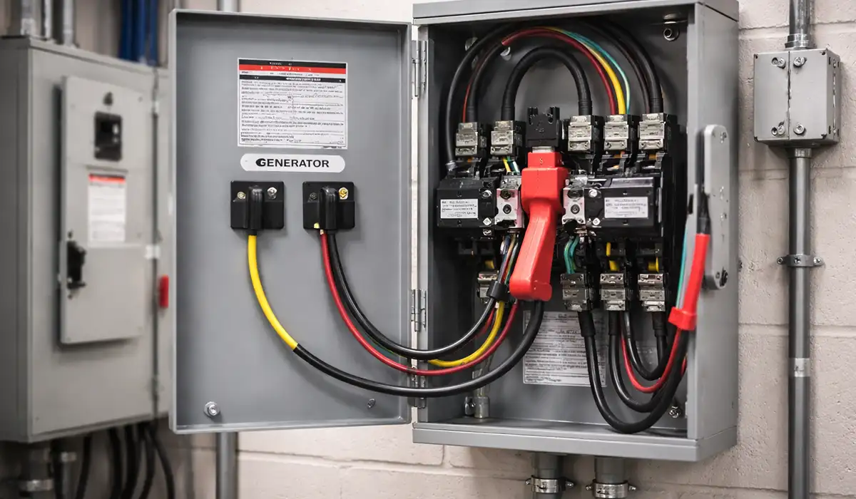
Double throw switches appear across electrical designs whenever there’s a need to choose between two circuits or power sources. One of the most common scenarios is switching between utility and backup generator power in industrial or commercial settings, where safe, manual changeover is critical.
In distribution panels and motor control centers, changeover switches help you isolate a load from one source and connect it to another without resorting to messy jumper wiring or unsafe workarounds. They’re also used in systems that must alternate between two loads from the same source or in control panels with complex logic paths.
On generator projects, a double throw changeover device may stand in a panel to ensure that only one power source is connected at a time, eliminating backfeed into another source — a requirement in many electrical codes.
Where the changeover sits inside a switchboard rather than a standalone enclosure, the assembly itself must meet UL 891.
Double Throw Safety Switches (Industrial)
In industrial distribution, a double throw safety switch (often a switch-disconnect switch) includes two interlocked switches designed so they cannot both be closed simultaneously. This prevents two sources from being tied together accidentally.
These safety switches are rugged, rated for significant current ranges (e.g., 30 A to over 1200 A), and often offered in fusible and non-fusible variants with features like visible blade mechanisms and padlockable OFF positions. They’re meant for environments where loading must be isolated quickly and distinctly, such as service entrance panels, generator changeover points, or industrial distribution racks.
| Type | Full form | Poles × throws | Terminals | Function |
|---|---|---|---|---|
| SPST | Single Pole, Single Throw | 1 × 1 | 2 | Basic ON/OFF on one circuit |
| SPDT | Single Pole, Double Throw | 1 × 2 | 3 | Selects between Source A and Source B on one circuit |
| DPST | Double Pole, Single Throw | 2 × 1 | 4 | Simultaneous ON/OFF on two circuits |
| DPDT | Double Pole, Double Throw | 2 × 2 | 6 | Full changeover on two circuits — e.g. line and neutral together |
| DT safety switch | Double Throw switch-disconnector | 2–4 poles × 2 | Varies | Interlocked so both sources cannot close at once; typically 30 A to 1200 A+ |
Break-Before-Make: The Requirement That Isn’t on the Front Page
A changeover switch must open the first source completely before closing the second. Any overlap — even a few milliseconds — parallels two sources. On a utility-to-generator changeover, that means backfeeding the network.
Not every double-throw device is break-before-make. Make-before-break DPDT switches exist and are used deliberately in signal routing and control circuits where an interruption is unacceptable. Specifying one for power changeover is a serious error, and the two are indistinguishable on a shelf.
Confirm the contact sequence on the datasheet. Don’t infer it from an ON-OFF-ON marking either — a centre-off position guarantees a gap in the handle travel, not necessarily in the contact timing of an ON-ON device.
Interlocks and break-before-make solve related but different problems. An interlock prevents two separate switches being closed together. Break-before-make governs the transition inside one switch. A changeover application needs both.
Manual Transfer Switches vs “Double Throw”
A manual transfer switch is a type of double throw function: it manually shifts your load between two power sources (like utility and generator) by flipping a handle or lever. This is essentially what many double throw safety switches do in a panelboard context.
The key difference between manual and automatic transfer switches (ATS) is that automatic versions detect power loss and switch without human intervention. Manual ones rely on a person to make the change when needed. For homes and small businesses, a manual approach might be cost-effective and straightforward; for facilities where uptime and quick response are critical, automatic switching is often required.
For the wider transfer switch category — manual, automatic, and the code requirements around each — see transfer switches.
Relevant Standards and Ratings
When you buy switches for industrial use, you’re not just picking amperage and housing style — you’re buying compliance with standards. IEC 60947-3 is the primary international standard for switches, disconnectors, switch-disconnectors, and fuse-combination units used in low-voltage distribution and motor circuits up to 1000 V AC or 1500 V DC. It defines how equipment must perform in normal and abnormal service, including tests, marking, and behavior expectations.
“Switch-disconnector” is a term you’ll encounter here. Essentially, it’s a device that combines switching capability with isolation — it can make and break current under operational conditions while also providing a clear open gap for safety and maintenance. Switches compliant with IEC 60947-3 and equivalent regional standards (such as UL 98 for the U.S.) are designed to be safe, predictable, and suitable for distribution panel roles.
Device compliance is necessary but not sufficient — the assembly containing it is verified separately under IEC 61439.
Safety & Compliance Considerations
Industrial double throw switches often include features beyond basic switching. Visible break or visible blade contacts let you confirm the circuit is open before working on it. Padlock or lock-off provisions support maintenance lockout/tagout procedures, and enclosure ratings must match the installation environment — outdoor, indoor, washdown, and so on.
Choosing devices rated for proper utilization categories and enclosures is essential for safety and inspection compliance.
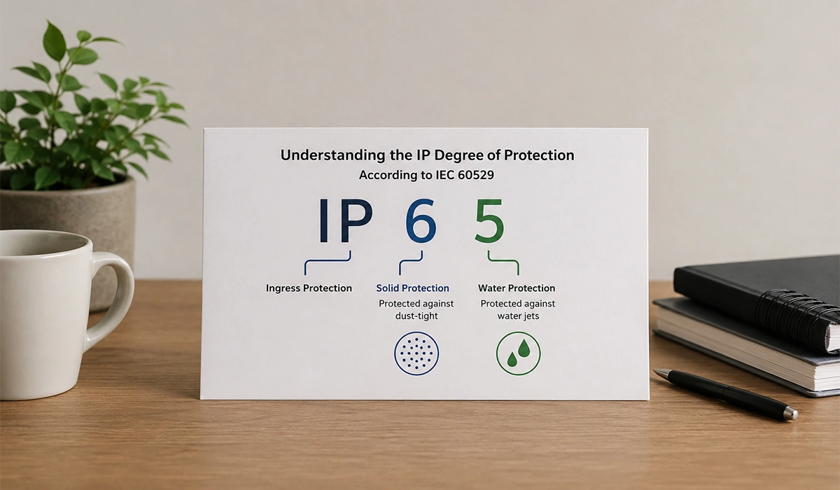
Enclosure selection is covered in detail in IP vs NEMA vs IK ratings.
How to Wire a DPDT Double Throw Switch
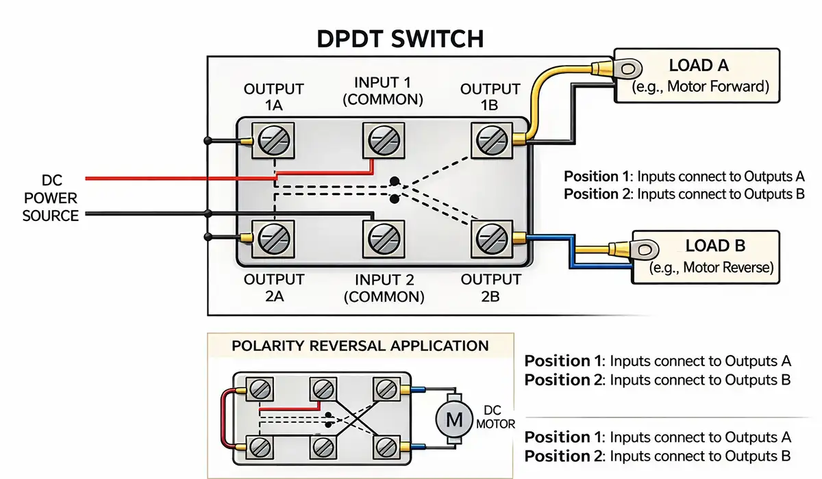
Wiring a DPDT switch is about understanding the common (COM) terminals and the two possible throws for each pole. Think of it as two SPDT switches sharing one actuator. This general pattern ensures that flipping the switch cleanly selects between two source paths or two load paths without partial connections or shorts.
- Identify the terminals: Most DPDT switches have six terminals — two common inputs and four outputs.
- Label your circuits: Mark the inputs and outputs you plan to connect (e.g., Source A/B or Load A/B).
- Connect sources and loads: Connect each common input to the respective source or load.
- Test in a de-energized state: Always verify continuity with a meter before applying power and check that connections match your desired behavior.
Size the conductors to each terminal for the full load — see three-phase cable sizing.
Common Wiring Patterns
Different wiring patterns you’ll see in practice include: one source feeding two loads (choose which load gets powered); two sources feeding one load (classic changeover); polarity reversal for motors and actuators in low-voltage DC circuits; and ON-ON-ON three-position configurations where some DPDT mechanisms allow three stable positions, useful for more complex routing.
3-Pole or 4-Pole: Whether to Switch the Neutral
On a generator changeover, whether the transfer switch breaks the neutral determines whether the generator is a separately derived system — and that determines where the neutral-earth bond belongs.
3-pole (solid neutral). Phases switch; the neutral stays connected through. The generator is not separately derived, and the neutral-earth bond stays at the service. Simpler, and the standard arrangement for most single-building installations.
4-pole (switched neutral). The neutral transfers with the phases. The generator becomes a separately derived system and needs its own neutral-earth bond. Required where an upstream RCD must function on generator supply, and where two permanent neutral-earth bonds would otherwise create parallel return paths.
Getting this wrong produces either a floating neutral on generator supply, or circulating current between two bonds. Neither is visible until something else goes wrong.
Sizing & Selection Checklist
When selecting a double throw or DPDT device, start with voltage and current ratings that match your system load, then confirm the number of poles and throw function (ON-ON or ON-OFF-ON). Enclosure rating must match the environment, and mechanical life together with terminal type determines long-term installation quality. Standards compliance (IEC 60947-3 or equivalent) and correct interrupting capacity are non-negotiable.
Good practice is to oversize modestly and confirm the device’s interrupting capacity meets your application’s worst-case currents.
Double Throw vs Single Throw (and Other Types)
A single throw switch simply connects or disconnects one circuit — it’s ON or OFF. A double throw switch offers two possible outputs for each pole, making it better for source selection, changeover functions, or systems requiring alternate paths. SPDT is the single-circuit version with two output choices, while DPDT adds a second circuit under the same actuator, which is handy in industrial panels where you want coordinated switching without separate switches.
If your job is simple ON/OFF, SPST or single throw may suffice. If you’re selecting between sources or need coordinated multi-circuit switching, a double throw variant is what you want.
Industrial Buying Guide: What to Look For
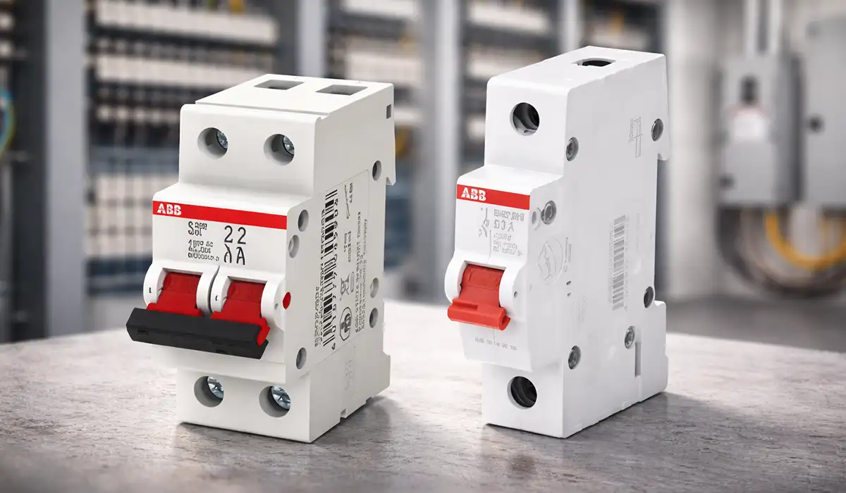
Specifiers scanning datasheets should focus on interlock mechanisms, visible isolation features, fusible vs non-fusible options, and short-circuit ratings appropriate to their panel. Devices with service entrance ratings or stacked switch options help save space while meeting code.
Match the utilization category to the load. IEC 60947-3 defines these as:
| Category | Load |
|---|---|
| AC-20 | Connecting and disconnecting under no load |
| AC-21 | Resistive loads, including moderate overloads |
| AC-22 | Mixed resistive and inductive loads, including moderate overloads |
| AC-23 | Motor loads or other highly inductive loads |
The A and B suffixes indicate operating frequency — A for frequent operation, B for infrequent. A distribution changeover switch operated a few times a year is a B application; a switch cycled daily is A.
Where the panel carries drives or switched-mode supplies alongside the changeover, EMC requirements under IEC 61000 apply to the assembly as a whole.
Specifying a Double Throw Switch: The Short Version
Six things decide the specification:
- Poles and throws — DPDT for line-and-neutral changeover; 3-pole or 4-pole for three-phase, depending on the neutral decision above
- Contact sequence — break-before-make for any power changeover, confirmed on the datasheet
- Utilization category — AC-21 resistive, AC-22 mixed, AC-23 motor, with A or B for operating frequency
- Current rating and interrupting capacity — against the prospective fault current at the point of installation, not the load
- Isolation features — visible break and padlockable OFF where the switch serves a lockout function
- Enclosure rating — matched to the actual environment, not the catalogue minimum
Standards compliance to IEC 60947-3 or UL 98 is the baseline, not a differentiator. What separates devices at the same rating is the contact sequence, the interlock design, and whether the isolation is genuinely visible.


Rate this article
Choose a rating from 1 to 5 stars.
No ratings yet