






If you’d rather listen than read, feel free to play the audio file below for the rest of this article.
The IEC 61439 Series: Structure, Parts and Current Editions
IEC 61439 governs the design, construction and verification of low-voltage switchgear and controlgear assemblies up to 1,000 V AC or 1,500 V DC. It replaced the IEC 60439 series, with the transition effectively complete by November 2014.
The series is modular. Part 1 holds the general rules; Parts 2 to 7 are product-specific.
| Part | Title | Scope |
|---|---|---|
| IEC 61439-1 | General Rules | Common Requirements for All Parts |
| IEC 61439-2 | Power Switchgear and Controlgear Assemblies (PSC) | General-Purpose LV Power and Control Panels |
| IEC 61439-3 | Distribution Boards for Ordinary Persons (DBO) | Household and Similar Boards |
| IEC 61439-4 | Construction Site Assemblies (ACS) | Temporary Site Power Distribution |
| IEC 61439-5 | Public Network Distribution (PENDA) | Utility-Side LV Distribution |
| IEC 61439-6 | Busbar Trunking Systems (BTS) | Prefabricated Busways |
| IEC 61439-7 | Specific Applications | Marinas, EV Charging, Market Squares |
Two rules govern how the parts combine, and most misapplications come from ignoring one of them:
- Part 1 is never invoked alone. It has no standalone application; a product part always carries it.
- Where a product part conflicts with Part 1, the product part wins for that assembly type.
So a compliant PSC-assembly is built to IEC 61439-1 and IEC 61439-2 read together, not to either in isolation.
Current editions:
| Standard | Edition | Published | Stability date |
|---|---|---|---|
| IEC 61439-1 | 3.0 | 5 May 2020 | 2030 |
| IEC 61439-2 | 3.0 | 22 July 2020 | 2030 |
Part 1 has no amendments, but carries corrigenda from December 2021 and September 2023. Cite the edition year in specifications: a submittal prepared to the 2011 edition and a review against the 2020 edition will not agree on temperature-rise verification.
For the wider framework, see our switchgear and busbar standards guide.
IEC 61439-1 Scope: The General Rules
Part 1 defines what applies to every low-voltage assembly, up to 1,000 V AC or 1,500 V DC. Its content divides into five domains:
(Keep the existing five-bullet list.)
Part 1 also defines the split between the original manufacturer and the assembly manufacturer, covered below. Engineers who go straight to the product part and skip the general rules tend to discover the omission at conformity review, when the technical file is already built.
For the wider standards picture, see our electrical standards guide.
IEC 61439-2 Scope: Power Switchgear and Controlgear Assemblies
Part 2 covers general-purpose low-voltage power switchgear and controlgear assemblies (PSC-assemblies) — the panels found in industrial plants, commercial buildings and machine rooms. Its scope covers assemblies with:
- rated voltage up to 1,000 V AC or 1,500 V DC
- nominal incoming supply frequency up to 1,000 Hz
- indoor and outdoor, stationary and movable, enclosed and open construction
- fixed and withdrawable designs, one-off or series production
- the generation, transmission, distribution and conversion of electrical energy, and the control of equipment
Motor control centres fall inside Part 2 when they meet the voltage limits. Assemblies for special service conditions — ships, rail vehicles — may use Part 2 where the relevant additional requirements are met.
What Part 2 excludes, because each has its own part or standard:
| Not covered by Part 2 | Governed instead by |
|---|---|
| Distribution boards for ordinary persons | IEC 61439-3 |
| Construction-site assemblies | IEC 61439-4 |
| Busbar trunking systems | IEC 61439-6 |
| Marinas, EV charging, market squares | IEC 61439-7 |
| Individual devices — breakers, contactors | IEC 60947 series |
Part 2 supplements Part 1: it adds, modifies or replaces general requirements for PSC-assemblies. Applying it to an assembly that belongs to another product part is the most common scope error in tender documents.
For component selection, see our guide to electrical wires and cables.
The Two-Manufacturer Model: Who Actually Owns Conformity
The two-manufacturer model is the most misread concept in the series, and it answers a question every procurement process eventually asks: when something is non-compliant, whose problem is it?
IEC 61439 separates the organisation that designs and verifies an assembly system from the organisation that builds individual panels. IEC 60439 left this ambiguous, which is precisely why the split was introduced.
The model determines who carries the design verification burden, who runs production checks, and who signs the declaration of conformity. It also interacts with the rated diversity factor, the Form of internal separation and every other characteristic the original manufacturer declared — because each of those is a boundary of the verified design. Step outside it and the obligations move.
Identify both parties before the first panel is built. On many projects they are the same company; on many others they are not, and nobody has said so in writing.
The Original Manufacturer: Owner of the Verified Design
The original manufacturer designed the assembly system and holds the design verification evidence. Usually this is the switchgear OEM that owns the type test reports and publishes the build rules.
What the original manufacturer owns:
- the completeness and correctness of all design verification
- the verified envelope — the range of busbar arrangements, device combinations, enclosure sizes, ventilation and cable entries within which a panel remains covered
- the technical documentation that tells an assembly manufacturer what may be varied and what may not
The envelope is the useful concept here. It is not a single tested panel; it is the family of configurations the evidence supports.
The Assembly Manufacturer: Builder and Signatory
The assembly manufacturer — panel builder, system integrator — builds the assembly. It may or may not be the same legal entity as the original manufacturer.
What the assembly manufacturer owns:
- building within the verified envelope
- routine verification on every unit produced
- the declaration of conformity for each completed assembly
- the build records behind each unit
The consequential rule: modify beyond the envelope and you take on original manufacturer obligations for what you changed. Fitting a larger device than the verified design allows, changing the busbar arrangement, adding ventilation openings or altering cable entries can all cross that line — and the panel builder then owns re-verification of the affected characteristics.
| Responsibility | Original Manufacturer | Assembly Manufacturer |
|---|---|---|
| Design Verification (Type Testing) | Yes — Performs or Holds Evidence | No — Uses OM’s Verified Design |
| Routine Verification (Every Unit) | Not Required | Yes — Every Assembly Produced |
| Declaration of Conformity | For the Verified Design | For Each Completed Assembly |
| Modification Beyond Envelope | Must Re-Verify | Assumes OM Obligations |
| Technical Documentation | Provides Design Envelope | Maintains Build Records |
| Marking of the Assembly | Defines Requirements | Applies Marking on Finished Unit |
Design Verification vs Routine Verification: Two Different Questions
IEC 61439 replaced the old type-tested / partially type-tested split with a framework that answers two separate questions:
- Design verification — is the design correct? Performed once per design, by the original manufacturer.
- Routine verification — was this unit built correctly? Performed on every assembly, by the assembly manufacturer.
Conflating them causes a specific, recurring procurement error. Asking a panel builder for routine verification records is reasonable and they should have them for every unit. Asking them to repeat a full short-circuit type test for each order is not — that is design verification, and the evidence already exists.
Design verification can be achieved three ways, and the standard treats them as equally valid when the evidence is traceable:
| Route | What it means |
|---|---|
| Testing | Physical verification of a representative assembly — temperature rise, short-circuit withstand, dielectric |
| Calculation | Engineering analysis, such as device power losses or short-circuit effects per IEC 60865-1 |
| Comparison with a reference design | Demonstrating the new design falls within an already verified one |
In practice, builders combine them — a tested temperature-rise reference alongside a calculated short-circuit withstand — covering every required clause without redundant testing. What matters is that each clause has recorded, traceable evidence in the technical file.
Routine verification runs on every completed assembly before dispatch and confirms manufacturing correctness, not design conformity.
| Routine Verification Check | Clause |
|---|---|
| Degree of Protection (Visual) | 11.2 |
| Clearances and Creepage Distances | 11.3 |
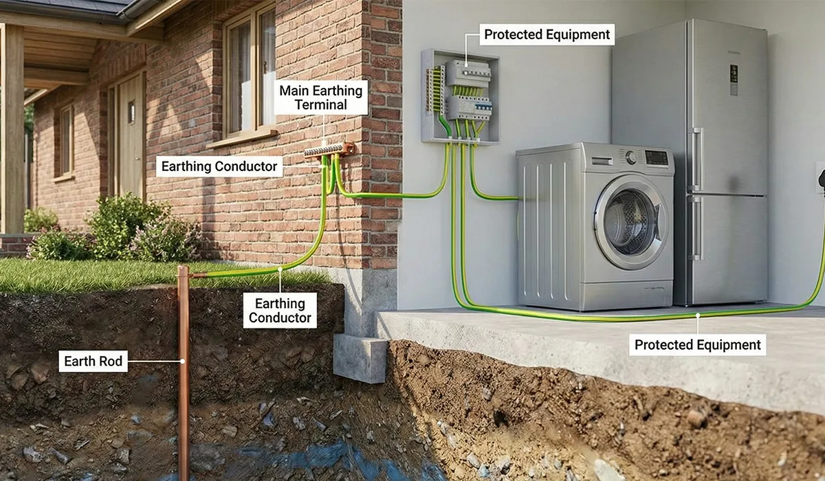
| Protection Against Electric Shock; Protective Circuits | 11.4 |
| Insertion of Devices and Components | 11.5 |
| Internal Electrical Circuits and Connections | 11.6 |
| Terminals for External Conductors | 11.7 |
| Mechanical Operation | 11.8 |
| Dielectric Properties (High-Voltage Test) | 11.9 |
| Wiring, Operational Performance, and Function | 11.10 |
These records normally form part of the Factory Acceptance Test pack.
For the clause-by-clause verification procedure, the rated diversity factor and the CE compliance pathway, see our dedicated guide to IEC 61439 design verification.
Forms of Internal Separation Under IEC 61439-2
Internal separation is the Part 2 characteristic most often written into a tender and least often understood. It describes how far the inside of an assembly is divided by barriers or partitions — and it is declared by the original manufacturer, agreed with the user, and marked.
Separation serves two practical purposes: protecting a person working on one functional unit from live parts in another, and limiting how far a fault propagates inside the assembly.
| Form | Busbars separated from functional units | Functional units separated from each other | Terminals separated |
|---|---|---|---|
| Form 1 | No separation | — | — |
| Form 2a | Yes | No | Terminals not separated from busbars |
| Form 2b | Yes | No | Terminals separated from busbars |
| Form 3a | Yes | Yes | Terminals not separated from each other |
| Form 3b | Yes | Yes | Terminals separated from each other, not from busbars |
| Form 4a | Yes | Yes | Terminals in the same compartment as their unit |
| Form 4b | Yes | Yes | Terminals in a separate compartment from their unit |
Three points worth putting in a specification:
- A higher Form is not automatically better. More barriers restrict airflow, which raises internal temperature and can force a lower rated diversity factor or a larger enclosure. Form 4b costs money and space, and is justified by a maintenance philosophy — working on one outgoing circuit while the rest stays live — not by a preference for higher numbers.
- Separation can be by metallic or non-metallic partitions, and that should be stated rather than assumed.
- The Form must match the declared temperature-rise verification. An assembly verified at Form 2 and built at Form 4b is outside its envelope.
Edition 3.0 of Part 2 clarified the internal separation requirements, so confirm which edition a vendor’s Form declaration was assessed against.
The Three Requirements That Drive Most of the Engineering
Temperature rise, short-circuit withstand and degree of protection account for most of the verification effort on a typical PSC-assembly, and they interact. A higher IP rating restricts ventilation, which raises internal temperature, which may force a lower rated diversity factor or a larger enclosure.
Every declared rating must appear on the nameplate and in the technical file. Undeclared performance is treated as absent, whatever the assembly is physically capable of.
The three subsections below summarize the requirements engineers reference most often.
For regional differences, see our comparison of AS/NZS 61439 and IEC 61439.
Temperature-Rise Limits: Reading Table 6 Correctly
Table 6 of IEC 61439-1 sets temperature-rise limits against a mean ambient air temperature up to 35 °C. The table is more nuanced than the single figure most specifications quote:
| Part of the assembly | Temperature-rise limit |
|---|---|
| Built-in components | Per the relevant product standard for that component |
| Terminals for external insulated conductors | 70 K |
| Busbars and conductors | No fixed value. Limited by the mechanical strength of the conducting material, the effect on adjacent equipment, the permissible temperature of insulating materials in contact, the effect on connected apparatus, and — for plug-in contacts — the nature and surface treatment of the contact. A maximum rise of 105 K must not be exceeded for bare copper. |
| Manual operating means | 15 K metal, 25 K insulating material |
| Accessible external enclosures and covers | 30 K metal surfaces, 40 K insulating surfaces |
Two things this table is regularly misquoted on:
- The 70 K figure belongs to terminals, not busbars. Applying it to busbars is conservative by 35 K and will oversize copper unnecessarily.
- The busbar limit is conditional before it is numerical. The 105 K ceiling is a maximum, not a target; the actual limit is whichever of the listed conditions binds first — usually the insulation in contact with the bar or the devices connected to it.
Verification is by test, calculation or comparison with a reference design. Edition 3.0 of Part 1 refocused temperature-rise verification and introduced a group rated current for circuits within a loaded assembly; Part 2 added requirements covering natural and active cooling, including circuits above 1,600 A.
Busbar temperature rise depends directly on the cross-section and joint quality achieved in fabrication; see our busbar sizing guide for the calculation side.
Short-Circuit Withstand: Icw and Ipk
The assembly must withstand the prospective short-circuit current at its installation point for a declared duration, commonly 1 second. Two ratings are declared:
- Icw — rated short-time withstand current, with its duration
- Ipk — rated peak withstand current
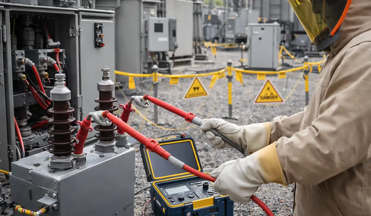
Verification is by short-circuit testing or by calculation following IEC 60865-1. Both effects must be covered: thermal (the I²t energy the conductors absorb) and electromagnetic (the forces that try to throw busbars apart, which is why bar supports and their spacing are part of the verified design).
An assembly protected by a current-limiting device may instead declare conditional short-circuit current, referenced to that specific device — which then becomes part of the envelope and cannot be substituted freely.
For panel design fundamentals, see our guide to types of electrical panels.
Degree of Protection and Protection Against Contact
Two related but distinct requirements apply.
Protection against direct contact. Live parts must be inaccessible to a standard jointed test finger — the IPXXB requirement. This is commonly written as IP2X, which uses the same finger test and adds protection against solid objects of 12.5 mm or more. Either wording achieves the contact protection; IP2X simply says more.
Declared degree of protection. The complete assembly must achieve its declared IP rating to IEC 60529, verified as a whole — door seals, gland plates, cable entries and ventilation openings included. An IP54 enclosure fitted with IP20 glands is an IP20 assembly.
Outdoor assemblies commonly require IP44 or IP54 as a minimum, depending on exposure. Note the trade-off with the temperature-rise section above: sealing an enclosure removes the ventilation the thermal design may have assumed.
For the IP code itself, see our guide to the IP degree of protection under IEC 60529. For EMC, see our industrial control panel EMC guide.
What Changed in Edition 3.0 (2020)
Both parts were reissued in 2020, and the changes affect how a design is verified rather than merely how the document is worded.
IEC 61439-1:2020 (Edition 3.0):
- Clarified that power converter systems, power supplies and adjustable speed drive systems follow their own standards when incorporated into an assembly
- Introduced a group rated current for circuits within a loaded assembly, and refocused temperature-rise verification accordingly
- Added DC requirements
- Introduced class I and class II assemblies for protection against electric shock
IEC 61439-2:2020 (Edition 3.0):
- Added annexes for photovoltaic installations
- Clarified internal separation requirements, with enhanced protection specifications
- Aligned its structure with Part 1:2020
- Extended temperature-rise verification for natural and active cooling, including circuits above 1,600 A
- Added IP considerations for actively cooled assemblies
If a vendor’s verification evidence predates 2020, ask which edition it was assessed against — particularly for temperature rise, where the basis changed, and for internal separation, where the wording did.
From IEC 60439 to IEC 61439: What the Transition Changed
The transition from IEC 60439 to IEC 61439 introduced both structural and technical changes. Specifically, the old TTA/PTTA distinction disappeared. Instead, every assembly is now a “verified assembly,” supported by traceable evidence. Furthermore, the manufacturer concept was formally split into the OM and AM roles.
Environmental factors affect panel performance significantly; learn about pollution degree and overvoltage classifications.
The table below summarizes the most consequential differences:
| Aspect | IEC 60439 (Old) | IEC 61439 (Current) |
|---|---|---|
| Classification | TTA / PTTA | Single Verified-Assembly Framework |
| Verification Methods | Mostly Physical Testing | Test, Calculation, or Comparison |
| Manufacturer Model | Single “Manufacturer” | OM + AM Split |
| Temperature Rise | Test Required in Most Cases | Calculation or Comparison Also Accepted |
| Short-Circuit Verification | Type Test Mandatory for TTA | Test or Calculation Accepted |
| Routine Testing Scope | Less Prescriptive | Explicit Mandatory Checklist (Clause 11) |
| Structure | One Standard | Modular: Part 1 + Product Part |
Notably, existing assemblies certified to IEC 60439 are not automatically withdrawn. However, new designs, new declarations of conformity, and most international tenders now require IEC 61439 compliance.
Conclusion: Two Parts, Two Manufacturers, One Technical File
IEC 61439-1 supplies the foundation — definitions, performance criteria and the verification framework. IEC 61439-2 applies them to general-purpose power switchgear and controlgear assemblies, modifying and adding where the product demands it. Neither works alone.
Four things carry most of the practical weight:
- Read both parts together, and cite the 2020 editions.
- Name the original manufacturer and the assembly manufacturer before the build starts, and treat the verified envelope as the boundary it is.
- Use all three verification routes. Testing, calculation and comparison are equally valid with traceable evidence, and insisting on physical tests you don’t need adds cost without adding compliance.
- Declare everything you rely on — ratings, Form, IP, Icw. Undeclared performance is not performance.
For enclosure protection across rating systems, see our comparison of IP and NEMA ratings.



Rate this article
Choose a rating from 1 to 5 stars.
No ratings yet