


EMC compliance for control panels is a mandatory requirement for industrial equipment sold in the EU, UK, and increasingly in the US and global markets. It means your panel must not generate disruptive electromagnetic emissions and must withstand the electromagnetic noise present in industrial environments — without malfunctioning. When a panel fails EMC compliance testing, the consequences range from costly re-design to delayed market launch, fines, and product recalls.
This guide covers everything a panel designer or systems integrator needs to know: the IEC 61000 standards framework, CE and FCC compliance paths, immunity and emissions test levels, wiring and shielding best practices, and how to build a CE technical file. Whether you are designing a new panel or troubleshooting EMC failures on an existing one, the checklist and recommendations below reflect real-world practice aligned with IEC 61000-6-2 and IEC 61000-6-4.
Prefer listening? You can play the audio version of the rest of this article below:
What is EMC compliance?
Electromagnetic Compatibility (EMC) compliance is the process of demonstrating that a piece of electrical or electronic equipment — in this case, an industrial control panel — satisfies two fundamental requirements:
- It does not emit electromagnetic energy above the permitted limits (emissions control).
- It continues to operate correctly when subjected to specified levels of external electromagnetic disturbance (immunity).
For control panels, EMC compliance matters more than it does for many other product categories. Panels sit at the heart of industrial processes: they house PLCs, drives, relays, and power supplies — all of which switch rapidly and generate high-frequency noise. At the same time, they must operate reliably in environments full of sources of interference: large motors, arc welders, variable-frequency drives, and long cable runs that act as antennas.
A panel that is not EMC-compliant can cause production downtime, corrupt data on fieldbus networks, trigger nuisance trips in safety systems, and create legal liability for the manufacturer or system integrator. In the EU, CE marking — which requires a declaration of conformity supported by a technical file — is the legal proof that EMC compliance has been achieved.
To understand Impact of IEC, UL, and CE Standards on Switchgear and Busbars better, see our complete guide on this subject.
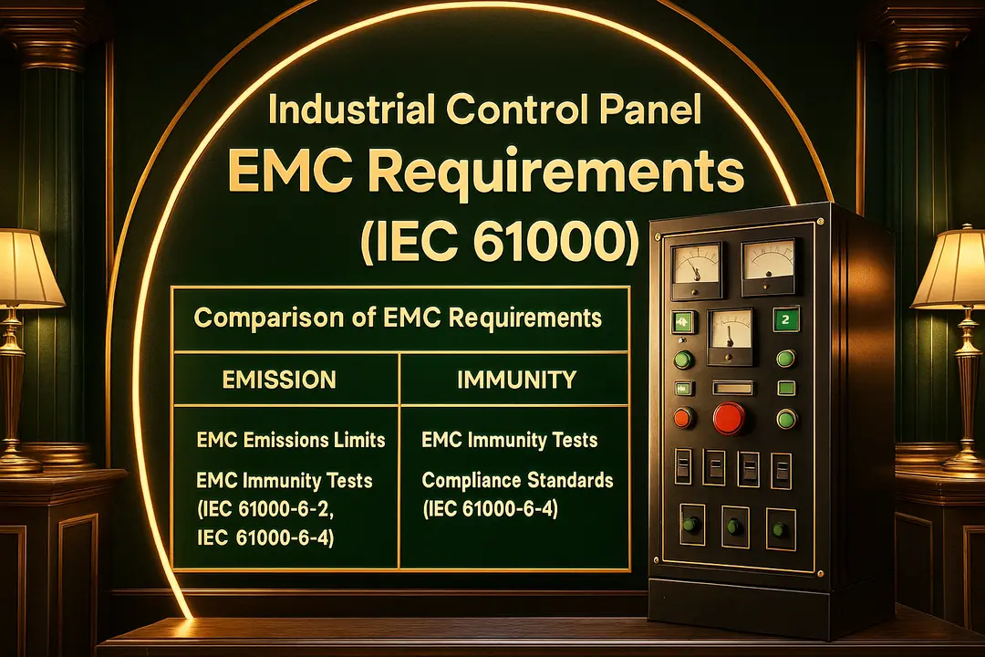
IEC 61000 series overview
Think of the EMC standards in two layers. The IEC 61000‑4‑x “Basic” parts describe how to test. The “Generic” parts say what level you must meet. For panels without a product standard, we usually apply:
• IEC 61000‑6‑2 for immunity (how robust the panel must be in an industrial site).
• IEC 61000‑6‑4 for emissions (how quiet the panel must be).
Panel builders working on machinery applications should also be aware of IEC 60204-1 (Safety of Machinery — Electrical Equipment of Machines). Section 4 of IEC 60204-1 contains specific EMC requirements for machinery electrical equipment, including rules for cable segregation, equipotential bonding, and electromagnetic compatibility of the overall machine. Importantly, IEC 60204-1 does not replace IEC 61000 — it references and builds upon it. If your control panel is part of a machine sold under the EU Machinery Directive, you must satisfy both standards simultaneously: IEC 60204-1 for the machinery-level requirements and IEC 61000-6-2 / 61000-6-4 for the panel-level EMC performance. In practice this means your CE technical file should reference both sets of standards, and your test plan should include verification against IEC 60204-1 clause 4 as well as the IEC 61000-4-x test suite.
Industrial plants are noisy by nature—big transformers, long cables, and fast switching—so Class A normally fits.
For more background information, please see this article.
IEC 61000‑6‑2 immunity requirements before any test, agree on performance criteria with the client:
A = no upset during/after test; B = temporary upset allowed but auto‑recovery; C = function may stop but can be restored.
Typical levels mapped to IEC 61000‑4‑x:
• ESD (‑4‑2): 4 kV contact, 8 kV air.
• Radiated RF (‑4‑3): 10–30 V/m.
• EFT/Burst (‑4‑4): 2–4 kV on power.
• Surge (‑4‑5): 1–4 kV L‑L, 2–4 kV L‑PE.
• Conducted RF (‑4‑6): 3–10 V, 150 kHz–80 MHz.
• Power‑freq magnetic field (‑4‑8): high class in heavy areas.
• Dips & interruptions (‑4‑11): defined residual voltages and times.
Mapping 6‑2 to 4‑x tests:
Your plan should name every port, the cable length, and the operating mode you will exercise for each test. Don’t forget “worst case” settings—for example, a VFD at the speed where it radiates the most.
Looking for detailed guidance on Types of Electrical Wires and Cables: A Complete Selection Guide for Every Application? Read our full article here.
IEC 61000‑6‑4 emission limits (CISPR 11 Class A)
Most panels are checked against CISPR 11 (ISM) Class A. We look at:
• Conducted emissions: 150 kHz–30 MHz with a LISN and EMI receiver.
• Radiated emissions: 30 MHz–1 GHz (and sometimes higher) in a chamber.
Class A is fine for industrial locations; for residential, additional measures are usually required.
Test setups for emissions
Conducted: the EUT sits on an 80 cm non‑conductive table over a ground plane; the LISN feeds power to the EUT and to the receiver.
Radiated: the EUT turns on a table while an antenna scans; we adjust orientation and cabling to catch the peak.
ESD, RF, EFT, surge — what actually works
• ESD: place TVS diodes at each exposed I/O and bond their ground pad straight to the metalwork (short, wide path).
• EFT/Burst: snubbers or MOVs on coils/relays; shielded entries with proper 360° clamps.
• Surge: coordinate MOVs/TVS with upstream SPD; keep return paths short.
• RF immunity: keep enclosure seams tight with EMC gaskets; avoid long shield “pigtails.”
Voltage dips and interruptions (‑4‑11)
PLCs and drives hate dips. Add DC ride‑through (bulk cap or DC UPS) or stagger the start‑up to prevent nuisance trips after power blinks.
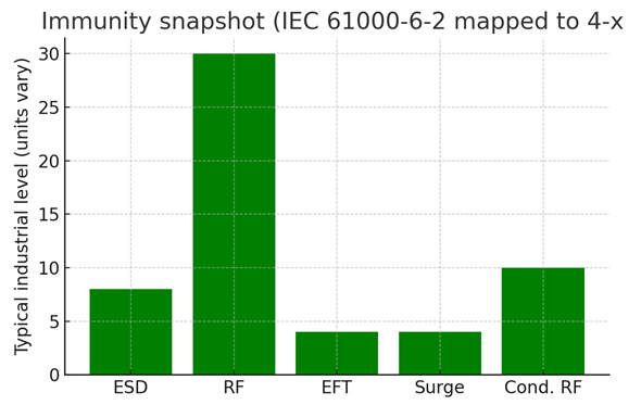
Figure: Green immunity levels for key IEC 61000‑4‑x tests (illustrative).
| Category | Standard | Frequency / Focus | Notes |
|---|---|---|---|
| Emissions | IEC 61000‑6‑4 / CISPR 11 Class A | CE 150 kHz–30 MHz; RE 30 MHz–1 GHz+ | Industrial Class A; LISN and chamber |
| Immunity | IEC 61000‑6‑2 via 4‑2/3/4/5/6/8/11 | ESD, RF, EFT, Surge, Cond. RF, PF magnetic, Dips | Define criteria A/B/C; test worst‑case modes |
EMC test plan and setup (template)
1) Freeze the exact hardware/firmware and operating modes.
2) List ports and cable types/lengths; pick representative samples.
3) Map each test to criterion A/B/C and expected behavior.
4) Prepare the CE technical file (reports, photos, schematics, risk assessment).
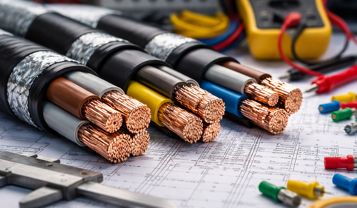
Wiring and cable routing rules
• Separate power, control, and sensitive analog/communications.
• Terminate shields 360° to the enclosure wall with clamps; no long tails.
• Bonding: scrape paint, use short/wide straps to a common ground bar.
• Filters: line filter at the panel inlet; ferrites on noisy devices and I/O.
Ferrites, chokes, and filters
• VFD input: a Class A line filter with a very short earth bond to the back‑plate.
• I/O and DC lines: common‑mode chokes for external cables; tiny ferrites on IC supply pins for differential noise.
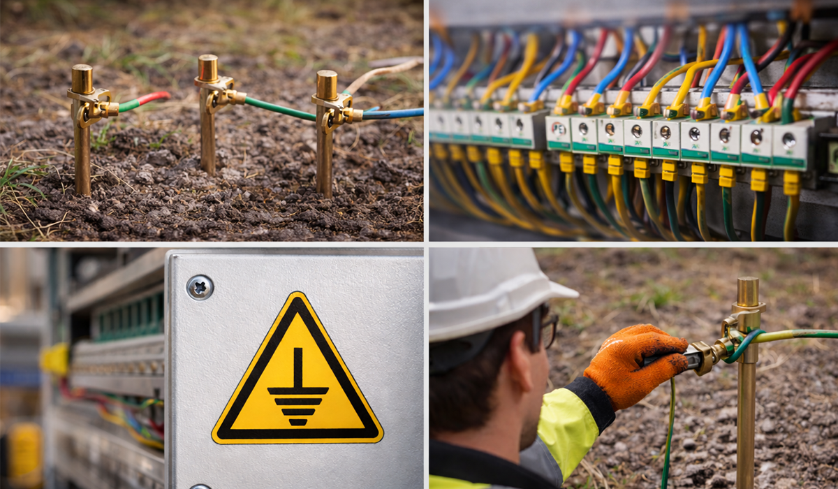
Shielding, grounding, bonding practices
Use conductive gaskets on doors and keep both hinge and latch sides bonded. Partition plates should have low‑impedance bonds to the ground bar so currents don’t wander.
VFD noise and mitigation
Expect the drive to be your loudest neighbor. Use shielded motor cables with 360° terminations at both ends, add dV/dt or sine‑wave filters for long runs, and keep motor leads well away from sensitive I/O—cross at 90° when paths must meet.
EU CE documentation workflow
• Keep drawings, BOM, firmware IDs, and reports in the technical file.
• Sign the Declaration of Conformity when the evidence is complete.
For more details on this subject, check out this guide.
EMC compliance cost and timeline for control panels
One of the most common questions from engineers starting the EMC compliance process for control panels is: how long does it take, and what does it cost? The honest answer depends heavily on how early in the design process EMC is considered. Here is a realistic breakdown:
Design-phase compliance (lowest cost)
If EMC best practices — correct cable routing, shielding, filtering, and grounding — are built into the panel design from the start, pre-compliance testing typically finds few issues. In this scenario:
- Pre-compliance scan at an in-house or local open-area test site (OATS): £500–£2,000 per day.
- Formal accredited lab test (UKAS/A2LA): £2,000–£6,000 for a typical industrial panel covering both conducted and radiated emissions plus the key immunity tests.
- Total timeline from design freeze to signed Declaration of Conformity: 4–8 weeks.
Interested in learning more? Our article on IEC 61439 Designs Verification & Compliances for Low Voltage assemblies in the EU expands on this topic.
Remediation-phase compliance (high cost)
When EMC is addressed only after the panel is built — often triggered by a first test failure — costs escalate significantly:
- Each additional lab booking to re-test after a fix: £1,500–£4,000.
- Re-design of cable routing, addition of filters or gaskets, or replacement of components can add £2,000–£15,000 in engineering and parts costs.
- Timeline can extend to 3–6 months if fundamental design changes are required.
Cost-saving tips
- Invest in a near-field probe set (£200–£800) for in-house pre-compliance scanning — it finds the dominant emissions sources before the lab does.
- Book a pre-compliance visit at a UKAS lab (half-day, typically £800–£1,200) before a full formal test — lab engineers will advise on layout and filter choices.
- Use simulation tools or EMC-aware PCB layout rules for custom electronics inside the panel to reduce the need for remediation hardware.
EU, UK, US, and Canada: EMC compliance comparison
The technical requirements for EMC compliance are broadly aligned globally, but the certification pathways differ. Here is a practical comparison for panel builders targeting multiple markets:
| Market | Standard / Scheme | Emissions basis | Immunity required? | Mark / Filing |
|---|---|---|---|---|
| EU | CE marking via IEC 61000-6-2 / -6-4 | CISPR 11 Class A | Yes — mandatory | CE mark + DoC + Technical File |
| UK (post-Brexit) | UKCA marking via same IEC 61000 standards | CISPR 11 Class A | Yes — mandatory | UKCA mark + DoC + Technical File, UK CA body involved |
| US (FCC) | FCC Part 15 Class A (digital) or Part 18 (ISM) | ANSI C63.4 / CISPR 22 | Not mandated — but strongly advised | Supplier Declaration of Conformity (SDoC) |
| Canada (ISED) | ICES-003 (digital apparatus) | ICES-003 Issue 7 (aligned with CISPR 22) | Not mandated | ISED label + SDoC; often combined with FCC filing |
Key practical tip: design for CISPR 11 Class A first
CISPR 11 Class A is generally tighter than FCC Part 15 Class A in the conducted emissions band (150 kHz – 30 MHz). A panel designed and tested to CISPR 11 Class A will typically satisfy FCC Part 15 Class A with minimal additional effort — making it the most efficient baseline when designing for both EU and US markets simultaneously. For UKCA, the technical requirements are currently identical to CE; the difference is administrative (UK Approved Body involvement and UKCA mark placement).
For a more detailed explanation, please check this guide.
Common EMC failures and fixes
• Radiated peaks from doors/seams → fit gaskets, tighten bonds, shorten cables.
• Conducted fails (150 kHz–10 MHz) → upgrade the line filter and its earth bond; add ferrites near noisy loads.
• EFT/Surge resets → add MOVs/TVS at I/O and mains entry; shorten returns; snub coils.
• Dip trips → provide ride‑through energy or a small DC UPS.
For further reading on Arc Flash Label Requirements: NFPA 70E & NEC 2026 Guide, see our related article here.