Arc flash label requirements define what information must appear on electrical equipment to warn qualified workers of arc flash hazards before they begin work. Under NFPA 70E Section 130.5(H), labels must display the nominal system voltage, the arc-flash boundary, and one — and only one — PPE approach. The NEC Section 110.16(B) (2023, expanded in 2026) independently requires permanent arc flash marking on service and feeder-supplied equipment rated 1,000 A or greater. Together, these two standards form the regulatory backbone of every arc flash labeling requirements program in the United States.
If you are looking for more information about How to Read an Arc Flash Label, it is recommended not to miss reading this article.
Alternatively, an audio version of this article is available below for your convenience:
NFPA 70E Label Requirements (130.5(H))
- Nominal system voltage
- Arc‐flash boundary (distance to 1.2 cal/cm²)
- Only one PPE approach on one label: (a) available incident energy with the working distance, or (b) PPE category from tables, or (c) minimum arc rating of clothing, or (d) site‐specific PPE level
Looking for detailed guidance on Impact of IEC, UL, and CE Standards on Switchgear and Busbars? Read our full article here.
DO NOT have both PPE category and incident energy on one tag. The tag must be durable to the environment (chemicals, heat, UV).
Which equipment requires arc flash labels?
Before reviewing what goes on an arc flash warning label, it helps to confirm which equipment is in scope. Under NEC 110.16(B) and NFPA 70E, the following must be marked:
- Service entrance equipment — all voltages
- Feeder-supplied equipment rated ≥ 1,000 A — switchboards, switchgear, panelboards, motor control centers (MCCs), and industrial control panels
- Any equipment where a qualified person may be exposed to an arc flash hazard during operation or maintenance
What changes with NEC 2026 arc flash label requirements?
The 2026 NEC cycle is the most significant expansion of arc flash labeling requirements in over a decade. Facilities compliant under 2023 rules may need additional labels. Key changes:
- Broader equipment scope — the 2026 revision lowers the ampere threshold and brings additional equipment types into mandatory scope
- Mandatory labeling extended — equipment previously in a recommended grey area becomes explicitly required to carry a compliant arc flash warning label
- Closer alignment with NFPA 70E 2024 — the 2026 NEC tracks NFPA 70E PPE method language more closely, reducing conflicts between the two standards
- Action required — audit current labels against the expanded scope before your next AHJ inspection; schedule an updated arc flash study if equipment has changed since the last review
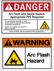
ANSI Z535 format guidelines Use signal words to convey alert level:
WARNING (orange): Indicates a serious hazard.
DANGER (red): Indicates the most serious hazards.
- Be straight‐forward and specific; use professional heavy duty tags.
NEC 110.16(B) – 2023 Additions (Installation Tagging)
- Permanent arc‐flash marking required on service equipment and feeder‐supplied equipment rated ≥ 1000 A (was 1200 A).
- Label must be in accordance with good industry practice (NFPA 70E) and meet NEC 110.21(B) durability standards.
Service vs. Feeder Labels
- Both service equipment and feeder-supplied gear (≥ 1000 A) require labels.
- Place labels on the exterior of panelboards, switchboards/switchgear, MCCs, and industrial control panels.
Want to dive deeper? Our article on IEC 61439 Designs Verification & Compliances for Low Voltage assemblies in the EU explains it thoroughly.
IEEE 1584 Calculations (Incident Energy Method)
Many facilities use IEEE 1584‑2018 to calculate incident energy and arc‑flash boundary.
Working distance is significant (Typical values: 18 in for LV panels/MCCs; 24 in for LV switchgear; 36 in for MV). Inputs can be short‑circuit current, protective device clearing time, enclosure/equipment class, and electrode configuration.
Arc-Flash Boundary (definition)
Arc-flash boundary is defined as the distance where incident energy equals 1.2 cal/cm² (the boundary of a second-degree burn).
It varies by equipment and calculation. Some facilities use a conservative standard value (e.g., 8–10 ft) for simplicity, but actual IEEE 1584 calculations for many LV panels often yield smaller distances (≈ 0.9–1.5 m / 3–5 ft)—verify by study.
Related Table — PPE Method Selection (NFPA 70E)
| Method | What Appears on Label | Pros | Considerations |
|---|---|---|---|
| Incident Energy Method | Incident energy (cal/cm²) at a stated working distance | Equipment‑specific; reflects actual device settings; generally preferred in modern programs | Requires study and periodic updates; results change if upstream system or protection changes |
| PPE Category Method | NFPA 70E PPE Category (1–4) and task description | Simpler when table limits are satisfied; no detailed study needed | Not equipment‑specific; must verify fault current and clearing time stay within table limits |
| Minimum Arc Rating | Minimum arc rating of clothing (cal/cm²) | Simple to communicate a floor for PPE | May be overly conservative or not reflect specific equipment tasks |
| Site‑Specific PPE Level | Defined site PPE level (e.g., Level 2) | Easy for internal consistency | Still needs engineering basis; keep mapping to arc ratings clear |
PPE Categories (NFPA 70E Tables)
NFPA 70E defines PPE Categories 1–4 for specified tasks/limits. Use either the Incident Energy Method or the PPE Category Method—not both on the same label. In practice, the incident‑energy method is now preferred in many facilities because it is equipment‑specific.
Label Placement & Durability
- Place labels where qualified persons can see them before any work (door exterior).
- Use materials that resist UV, chemicals, and heat (thermal‑transfer or engraved industrial labels are common).
Update Frequency & Triggers
- Review interval: at least every 5 years to confirm data supporting the label is still accurate; document the review.
- Update sooner after system changes, especially upstream: utility transformer size/impedance changes, feeder/source reconfiguration, protective device type/setting changes, new equipment, or after a fault event.
To understand CE Marking for Industrial Control Panels better, see our complete guide on this subject.
Maintenance Mode Reduction (how it’s implemented)
Energy‑reducing maintenance switching temporarily forces instantaneous or very fast tripping to reduce arcing duration during specific tasks. It is commonly provided via a circuit breaker maintenance switch/setting or a protective relay feature; related techniques include Zone Selective Interlocking (ZSI) and active arc‑flash mitigation. Enable only for the job and disable afterward, and capture the status/steps in the energized work permit.

46/200 45 words Standards & Safety (U.S.)

OSHA 29 CFR 1910: OSHA does not require arc-flash equipment labeling, but the NFPA 70E are accepted as industry consensus standards for electrical safety compliance.
• NFPA 70E: The workplace labeling and work practices (130.5/130.5(H))
• NEC (NFPA 70): Marking of installation – 110.16(B) (2023), Durability – 110.21(B).
Conclusion: Arc Flash Label Requirements
Arc flash label requirements are not a formality — they are the first line of defense for any qualified worker who opens an electrical enclosure. Getting them right means understanding two overlapping frameworks: NFPA 70E 130.5(H), which governs what a label must say, and NEC 110.16(B), which governs which equipment must carry one.
A compliant arc flash warning label must include:
- The nominal system voltage and arc-flash boundary distance
- One — and only one — PPE approach: incident energy, PPE category, minimum arc rating, or a site-specific level. Never mix methods on the same label.
- Durable materials suited to the installation environment, meeting NEC 110.21(B)
With the NEC 2026 cycle expanding the scope of mandatory arc flash labeling, now is the right time to audit your equipment, revisit your arc flash study, and confirm every label reflects current system conditions. Labels based on outdated fault current data or superseded protective device settings create a false sense of compliance — and real risk for workers.
If your facility uses the incident energy method with IEEE 1584-2018 calculations, your labels are already as accurate and equipment-specific as the standard allows. If you are still using PPE category tables or conservative default arc-flash boundaries, an arc flash study is the next step toward a defensible, worker-protective arc flash labeling requirements program.
For authoritative guidance on arc-flash labeling and safe electrical work practices, see NFPA 70E® — Standard for Electrical Safety in the Workplace. This consensus standard (including §130.5(H)) defines required label content, arc-flash boundary determination, and PPE selection, and is widely recognized across industry and safety programs.
FAQ About Arc Flash Label Requirements