

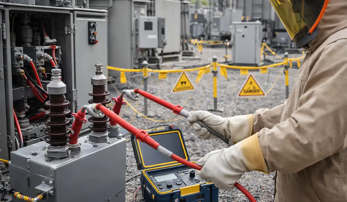





Testing is usually categorized into acceptance testing (before equipment goes into service) and maintenance testing (while equipment is in service). The former proves things meet design specs and standards, and the latter catches degradation before it leads to a breakdown. Standards give us a reliable framework so results are consistent across labs and service crews around the world.
When you read other articles that repeat the same bullet points about voltage testing, what you’re missing is why these tests matter in real life: they’re your early-warning system for faults that are invisible to the naked eye but capable of causing catastrophic outages if left unchecked.
If you’d rather listen than read, feel free to play the audio file below for the rest of this article.
What Is High Voltage Testing? (Definition & Purpose)
HV test is shorthand for high voltage test. It refers to applying electrical stress above normal service levels to equipment in order to confirm the insulation system is robust, compliant and ready for service.
High voltage testing refers to applying electrical stress higher than normal service levels to equipment in order to confirm that its insulation system is robust, compliant, and ready for service. Think of it as a probe that deliberately stresses components to reveal hidden weaknesses. These tests are vital for ensuring products will reliably withstand overvoltage conditions such as lightning strikes, switching surges, or unexpected grid disturbances.
Most industrial electrical systems rely on complex insulation systems. If those fail under stress, the consequences range from nuisance tripping to catastrophic failures that bring down whole substations. That’s why high voltage tests are specified in design and quality verification processes.
Standardization bodies like IEC and IEEE define how tests should be performed so results are consistent and repeatable. These standards distinguish between acceptance and maintenance testing: acceptance tests establish baseline performance at the factory or during commissioning, and maintenance tests track ongoing health during service life.
Core Types of High Voltage Tests
There’s no one-size-fits-all high voltage test. What you choose depends on the asset type, its rated voltage, expected stressors, and whether you’re doing acceptance or maintenance checks. Below is a breakdown of the major categories along with a quick-reference comparison table.
| Test | What it does | Voltage | Acceptance / maintenance | Standard |
|---|---|---|---|---|
| AC / DC hipot | Applies voltage above service level to prove withstand; pass/fail on leakage and breakdown | Above rated | Both | IEC 60060; IEEE 400.2 for cable VLF |
| Impulse (BIL) | Short high-energy pulses simulating lightning or switching surges | Tens to hundreds of kV peak | Type test, factory | IEC 60060-1 |
| IR / PI / DAR | Resistance to current flow at DC; tracks moisture ingress and degradation | 500 V – 10 kV DC | Maintenance | IEEE 43 (rotating machines) |
| Partial discharge | Detects localised discharge at voids and defects, quantified as apparent charge | At or near service | Both | IEC 60270 |
| Tan δ / power factor | Dielectric loss, trended for aging, moisture and contamination | At or near service | Maintenance | IEEE 400.2; IEC 60270 |
AC & DC Dielectric Withstand (Hipot) Tests
Dielectric withstand tests (often called hipot tests) are the workhorses of high voltage verification. The goal is simple: apply voltage that’s higher than what the equipment normally sees and observe how it behaves. If the insulation holds without excessive leakage current or breakdown, the part passes. If not, something weak in the insulation might lead to flashover under real service conditions.
AC hipot applies alternating voltage at power frequency, or at very low frequency (VLF) for field cable work. DC hipot applies direct voltage.
On cable, the choice is largely settled. DC hipot remains appropriate for laminated paper insulation (PILC) and for newly installed extruded cable. It is no longer supported by IEEE 400 for aged extruded cable (XLPE, EPR), for two reasons:
- It damages what it tests. DC stress traps space charge in the insulation, creating localised field intensification. When AC is reapplied before those charges dissipate — which can take 24 to 48 hours — the enhanced field can cause immediate failure. DC stress also accelerates existing water trees into conductive paths.
- It doesn’t find defects. Per IEEE 400, even massive defects produce minimal leakage current under DC and are missed. The standard defines no acceptable leakage value for DC hipot on extruded cable, because the measurement isn’t diagnostic.
For aged MV cable, use VLF withstand or offline PD testing instead. If DC is proposed, the asset owner should be able to cite the standard and cable type that support it.
Dwell time for a routine hipot is typically 60 seconds; VLF withstand per IEEE 400.2 is usually 2.5–3.0 × V₀ for 5 minutes. IEEE 400-2012 requires a discharge period of at least four times the test duration before anyone touches the cable.
You’ll also see hipot called a proof test or voltage proof test — the same thing. It proves the insulation withstands a defined overvoltage for a defined time; it doesn’t measure how much margin is left.
Impulse (Surge / BIL) Testing
Impulse tests mimic fast, high-energy events like lightning strikes or switching surges. These produce short-duration high-voltage pulses that stress insulation in ways AC/DC steady voltages don’t. The Basic Insulation Level (BIL) is the minimum impulse voltage the insulation should tolerate without flashover. Impulse generators, dividers, and precise measurement chains are needed because wave shape and peak values both matter.
Insulation Resistance (IR) Testing
While hipot tests push insulation to its limits, insulation resistance testing measures how well the insulation resists current flow at lower (but still high) DC voltages. Values are often time-indexed — IR after 1 minute, Polarization Index (PI), and Dielectric Absorption Ratio (DAR). These metrics help you spot moisture ingress or degradation before it becomes a failure. IR tests are common in maintenance programs because they track condition over time.
Partial Discharge (PD) Testing & Monitoring
Partial discharge (PD) is a localized electrical discharge that doesn’t completely bridge the insulation but indicates weak spots, voids, or contamination. PD testing detects these early precursors to failure. IEC 60270 defines standardized methods to measure PD activity in terms of apparent charge. PD is useful both in factory qualification and in service diagnostics because it often precedes full breakdown by a significant margin.
Tan Delta / Power Factor Tests
These tests measure dielectric losses — essentially how much energy insulation dissipates as heat under electrical stress. Tan δ and power factor are two related ways of expressing the same phenomenon. High loss values typically mean aging insulation, moisture, or contaminants. Regular tracking of these values helps predict when an asset might be nearing its end of useful life.
Standards & Compliance Map
Standards are like the grammar rules of high voltage testing. If you want your test results recognized and defensible, you play by these rulebooks. The two central IEC standards are IEC 60060 (dielectric test techniques) and IEC 60270 (partial discharge measurements), but additional standards apply depending on asset class.
The current edition is IEC 60060-1:2010, available from the IEC webstore.
IEC 60060 Series (Test Techniques & Withstand)
The IEC 60060 series lays down how to conduct dielectric tests including AC, DC, and impulse types, covering voltage levels, definitions, and measurement protocols for equipment above certain voltage thresholds. It is the backbone of how dielectric withstand and impulse tests are structured globally.
IEC 60270 (Partial Discharge Measurements)
IEC 60270 standardizes partial discharge measurement techniques and definitions. It explains how PD is quantified in terms of apparent charge and how to set up measurement circuits. This gives you confidence that PD data from different labs is comparable and traceable.
Other Norms & References
While IEC 60060 and IEC 60270 are central, other references apply depending on your asset class. IEC 61439 governs dielectric tests for low-voltage switchgear assemblies.
A distinction worth keeping clear: IEC 61000-4-5 (surge immunity) uses a similar 1.2/50 µs waveshape, but it is an EMC test on equipment ports at hundreds of volts to a few kV — not an insulation withstand test. IEC 60060 impulse testing applies tens to hundreds of kV to the insulation system itself. Same nominal waveshape, entirely different energy and purpose.
IEEE adaptations of IEC methods also exist for specific apparatus like switchgear.
Step-by-Step Test Procedures (Field & Factory)
This is where the rubber meets the road. Best practices help you avoid disasters like hitting the wrong test voltage on a delicate device. Think of this as a checklist combined with a practical how-to.
Preparing the Device Under Test (DUT)
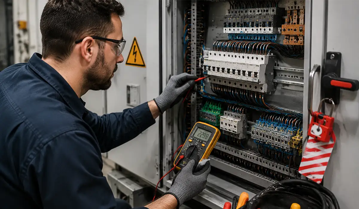
Before you ever apply voltage, visually inspect for damage, dirt, and corrosion and verify nameplate ratings. Confirm environmental conditions (moisture, temperature) are within limits, ensure proper isolation and grounding points are identified, and complete lockout/tagout (LOTO) before setting up barriers so no one wanders into a live zone. This pre-test checklist saves lives and prevents equipment damage.
Establish and verify the ground connection before anything else — an ungrounded or poorly grounded DUT makes every subsequent reading unreliable and every subsequent step dangerous. See grounding and earthing system design.
Running a Hipot / Withstand Test
Start at zero volts. Slowly ramp to your target test voltage level appropriate for the DUT class and standard. Hold that voltage for the specified dwell time (often a few minutes), continuously monitoring leakage current. If leakage stays below the limit and no flashover is observed, you pass. If not, that’s a sign of insulation weakness requiring investigation before the asset enters service.
Performing IR / PI / DAR
Select a DC voltage suitable for insulation resistance work — often 1 to 10 kV depending on asset class. Measure resistance at set intervals (e.g., 30 s, 60 s) to calculate IR, PI, and DAR. Track these values over time to spot trends. Temperature can skew resistance readings, so apply temperature corrections or rely on trending rather than absolute numbers.
| Metric | Calculation | Interpretation |
|---|---|---|
| DAR | IR at 60 s ÷ IR at 30 s | Below 1.25 questionable · 1.6 or above good |
| PI | IR at 10 min ÷ IR at 1 min | Below 1.5 unacceptable · 2.0–4.0 good · above 4.0 excellent |
Two caveats that matter more than the numbers.
PI loses meaning on modern insulation. IEEE 43 notes that where the 1-minute IR already exceeds 5,000 MΩ, the polarisation index may not be a useful indicator — the absorption current is already negligible, and the ratio becomes noise.
Temperature dominates everything. Insulation resistance roughly halves for every 10 °C rise. Correct readings to a 40 °C reference or trend at a consistent temperature. An uncorrected reading compared against last year’s is comparing two different measurements.
Conducting PD Tests (Offline / Online)
For factory or lab PD tests, use coupling capacitors and PD sensors to capture activity while a controlled AC or DC stress is applied. Noise mitigation is crucial because external interference can mask real PD signals. Calibrate your setup with a PD calibrator so results are traceable. “PD inception voltage” is the point where PD activity starts, and “PD extinction voltage” is where it stops as voltage is reduced.
Impulse Testing Basics
Impulse tests require specialized generators and measuring dividers. Standardized wave shapes (like 1.2/50 µs for lightning impulses) ensure consistency. Multiple shots may be applied to confirm insulation performance. Impulse tests aren’t routine for every asset but are common for type and design verification on transformers, switchgear, and high-voltage cables.
Equipment Selection, Setup & Calibration
Picking the right tool is half the battle. Your tester should cover the voltage range of your DUT with headroom for safety and measurement accuracy. Features like programmable ramps, data logging, and sturdy enclosures matter in tough environments. A 10 kV IR tester is typical for medium voltage assets, but always verify with relevant standards and OEM specs.
PD testing requires coupling capacitors, HFCT sensors, filters, and analytics software to clean noise and interpret patterns. Impulse generators vary by energy rating and should have precise waveform generation, while resistive/capacitive voltage dividers and high-speed digitizers ensure accurate readings. Routine calibration by accredited labs maintains traceability so your measurements hold up under audit.
Safety First — Risk Controls for High Voltage Testing
Testing at high voltages is literally dangerous if mishandled. Essential risk controls include written procedures and permits that define who does what and when, barriers and warning signage so untrained people stay clear, interlocks and emergency stops that kill energy instantly, personal protective equipment (PPE) like insulating gloves and face shields, and grounding and creepage clearance checks to prevent unintended current paths. Always treat high voltage as live until it’s verified otherwise.
Sector-Specific Applications & Tips
Low-Voltage Assemblies (IEC 61439)
Even LV switchgear needs dielectric tests after assembly changes. These tests prove clearances and creepage distances are sufficient for safety. Standards compliance for these assemblies is well-documented, and the comparison between regional variations is important for international projects.
Cables (MV / HV)
Cable tests often involve DC, VLF, and AC withstands coupled with PD and tan δ diagnostics.
VLF applies AC at about 0.1 Hz instead of 50/60 Hz. Because charging current scales with frequency, capacitive reactance at 0.1 Hz is roughly 600 times lower than at 60 Hz — so a test set that would be trailer-mounted at power frequency fits in a case, while still applying genuine alternating stress. That combination, portability plus true AC, is why VLF replaced DC for field testing of extruded MV cable.
Where cable runs terminate into switchgear, the assembly has its own verification requirements — see standards for switchgear and busbar systems.
Transformers & Rotating Machines
IR, tan δ, and PD tests on windings help ensure longevity. Routine applied voltage withstand tests give confidence before energizing equipment.
Transformers
Transformer testing has its own battery, most of it carried out at the factory and repeated selectively in service:
- Turns ratio (TTR) — verifies winding ratio and detects shorted turns
- Winding resistance — finds loose connections, broken strands, tap changer problems
- Excitation current — sensitive to core and winding defects
- Insulation resistance and PI — condition of winding insulation, corrected for temperature
- Tan δ / power factor — moisture and aging in windings and bushings, trended over time
- SFRA (sweep frequency response analysis) — detects winding movement after a through-fault or transport; compared against a baseline fingerprint
- Applied and induced voltage withstand — factory type and routine tests per IEC 60076-3
- Impulse (BIL) — factory type test
The one that most often gets skipped is the SFRA baseline. Without a fingerprint taken when the unit was healthy, a later SFRA trace has nothing to compare against — and that’s exactly when you need it, after a through-fault or a relocation.
Rotating Machines
IR, PI, tan δ and PD on windings, per IEEE 43 for insulation resistance. Routine applied voltage withstand gives confidence before re-energising after an outage or rewind.
Data, Documentation & Trending
A high voltage test isn’t complete without a record. Log environmental conditions (temperature, humidity), test setup and connections, voltage profiles and durations, leakage current and PD levels, resistance values, and pass/fail statements. Trending these values over time is a predictive maintenance gold mine that helps you schedule intervention before failure, not after.
Mini Case: Catching Moisture in an MV Motor with 10 kV IR Test
A medium voltage motor failed unexpectedly in service because moisture ingress over a rainy season degraded the insulation. By introducing a 10 kV insulation resistance test during routine maintenance and tracking PI values over months, engineers caught a downward trend before breakdown. Early reconditioning prevented costly downtime and extended motor life.
The case also depends on the frame being properly bonded — an ungrounded motor frame makes IR readings meaningless. See types of earthing systems.
Conclusion
Frequently Asked Questions (FAQs)




Rate this article
Choose a rating from 1 to 5 stars.
No ratings yet