


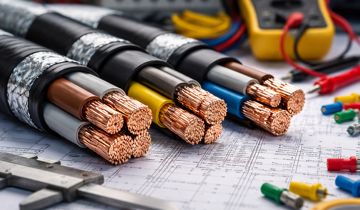





Why Proper Three-Phase Cable Selection Matters
An undersized or incorrectly specified cable puts the entire electrical system at risk. The consequences of a wrong choice include reduced equipment efficiency, premature insulation failure, tripped protection devices, and in worst cases, electrical fires. By following a structured selection process — and referencing the correct electrical standards for your region — engineers can prevent these issues from the start.
Key Factors in Three-Phase Cable Selection
Before calculating cable size, you must evaluate the following parameters. Understanding the types of electrical wires and cables available is an important first step, as different cable constructions are suited to different operating environments and load types.
| Factor | Description | Impact Level |
|---|---|---|
| Load Current (Ampacity) | The actual current drawn by the equipment under full load | Critical |
| Conductor Cross-Sectional Area | Determines current capacity and resistance of the cable | Critical |
| Route Length | Longer runs increase resistance and voltage drop | High |
| Permissible Voltage Drop | Maximum allowable voltage loss from source to load | High |
| Installation Environment | Buried, overhead, conduit, ambient temperature | High |
| Type of Electrical Load | Resistive, motor, VFD — affects starting current requirements | Medium |
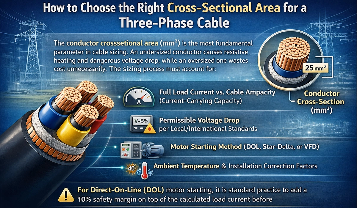
How to Choose the Right Cross-Sectional Area for a Three-Phase Cable
The conductor cross-sectional area (mm²) is the most fundamental parameter in cable sizing. An undersized conductor causes resistive heating and dangerous voltage drop, while an oversized one wastes cost unnecessarily. The sizing process must account for:
- Full load current vs. cable ampacity (current-carrying capacity)
- Permissible voltage drop per local/international standards
- Motor starting method (DOL, Star-Delta, or VFD)
- Ambient temperature and installation correction factors
Motor circuits are not sized to full-load current. Under NEC 430.22, branch-circuit conductors supplying a single continuous-duty motor must have an ampacity of not less than 125% of the motor’s full-load current rating — a 25% margin, not 10%. IEC practice under IEC 60364-5-52 arrives at a similar place through overload-device coordination rather than a fixed multiplier.
Size to the nameplate FLC × 1.25, then apply derating factors for temperature and grouping on top of that. Starting current matters separately: it doesn’t size the conductor, but it does need checking against the cable’s short-circuit thermal withstand.
Motor Starting Method Comparison
| Starting Method | Starting Current | Cable Sizing Note | Typical Application |
|---|---|---|---|
| DOL (Direct-On-Line) | 600–700% of FLC | Add 10% margin; check thermal withstand | Small motors up to ~15 kW |
| Star-Delta (SSD) | ~200% of FLC | Size for full load; starting current is reduced | Medium motors 15–75 kW |
| VFD (Variable Frequency Drive) | Controlled ramp-up | Derate for harmonics; use shielded cable | Variable speed, large motors |
Route Length, Resistance, and Voltage Drop
Cable length has a direct and proportional effect on electrical resistance, and therefore on voltage drop. The longer the cable run, the higher the cumulative resistance, and the more voltage is lost between the source and the load. This is not merely a performance issue — excessive voltage drop can prevent motors from starting, cause contactors to drop out, and reduce the service life of equipment.
The standard voltage drop formula for three-phase systems is:
ΔV = √3 × I × L × ρ / A
Where: ΔV = voltage drop (V), I = load current (A), L = one-way cable length (m), ρ = resistivity of conductor (Ω·mm²/m), A = cross-sectional area (mm²).
A limitation worth knowing: this is the resistive form. It’s accurate for smaller conductors, but above roughly 35–50 mm² the cable’s inductive reactance becomes significant, and the full expression is:
ΔV = √3 × I × L × (R·cosφ + X·sinφ)
At low power factor on a large feeder, the resistive-only calculation can under-predict voltage drop noticeably. For anything above 50 mm², use the manufacturer’s mV/A/m figure, which already includes reactance at a stated power factor.
For long cable runs, increasing the cross-sectional area is the primary solution to keep voltage drop within acceptable limits — typically 3–5% for motor circuits per IEC standards. Engineers designing busbar-fed distribution systems should also review the relevant IEC 61439 design verification requirements to ensure end-to-end compliance across the entire power path.
Three-Phase Cable Size Chart: mm², AWG and Typical Ampacity
The tables below are a starting point for reference conditions — three loaded conductors, 30 °C ambient, free air or conduit as noted. Every figure must be derated for your actual installation using the factors in the next section, and checked against the standard enforced in your jurisdiction.
| mm² | Nearest AWG/kcmil | Typical ampacity, 3 conductors in conduit (A) | Typical ampacity, free air (A) |
|---|---|---|---|
| 1.5 | 16 | 17 | 22 |
| 2.5 | 14 | 24 | 30 |
| 4 | 12 | 32 | 40 |
| 6 | 10 | 41 | 51 |
| 10 | 8 | 57 | 70 |
| 16 | 6 | 76 | 94 |
| 25 | 4 | 101 | 119 |
| 35 | 2 | 125 | 148 |
| 50 | 1 | 151 | 180 |
| 70 | 2/0 | 192 | 232 |
| 95 | 3/0 | 232 | 282 |
| 120 | 4/0 | 269 | 328 |
| 150 | 300 kcmil | 300 | 379 |
| 185 | 350 kcmil | 341 | 434 |
| 240 | 500 kcmil | 400 | 514 |
How to use it: take motor FLC × 1.25 (or actual load current for non-motor circuits), apply the temperature and grouping derating factors below, then pick the first size whose derated ampacity meets or exceeds that figure — and finally check voltage drop over your actual route length. Ampacity and voltage drop are separate tests; on long runs, voltage drop usually decides the size, not ampacity.
I’ve given typical values for orientation. Before publishing, have these verified against the specific table your audience works to — IEC 60364-5-52 Table B.52.x or NEC Table 310.16 — since the figures differ between standards and between installation methods. Getting a reference table right matters more than getting it published quickly.
Voltage Drop Limits by Application (IEC Reference)
| Application Type | Max Permissible Voltage Drop | Consequence of Exceeding |
|---|---|---|
| Motor circuits | 3–5% | Failure to start, overheating, torque loss |
| Lighting circuits | 3% | Flickering, reduced lumen output |
| General power distribution | 5% | Equipment malfunction, efficiency loss |
| Sensitive electronic loads | 1–2% | Errors, data corruption, shutdowns |
Cable Insulation Types: Choosing the Right Material
Insulation material determines the cable’s maximum operating temperature, its suitability for different environments, and its fire performance. The wrong insulation in a harsh environment leads to premature degradation and safety risks. In hazardous classified areas, cable selection must also comply with ATEX and IECEx zone requirements, which impose additional constraints on insulation and sheathing materials.
| Insulation Type | Max Temp (°C) | Best For | Key Advantage |
|---|---|---|---|
| PVC (Polyvinyl Chloride) | 70°C | Indoor, dry environments | Low cost, widely available |
| XLPE (Cross-Linked Polyethylene) | 90°C (up to 250°C short-circuit) | High-temp, underground, industrial | Superior thermal and chemical resistance |
| EPR (Ethylene Propylene Rubber) | 90°C | Flexible, wet, offshore applications | Excellent flexibility and water resistance |
| LSZH (Low Smoke Zero Halogen) | 70–90°C | Tunnels, public buildings, confined spaces | Minimal toxic fumes in fire |
| Fire-Resistant (FP/CI) | Up to 950°C (circuit integrity) | Emergency circuits, fire alarm systems | Maintains function during fire |
Installation Conditions and Derating Factors
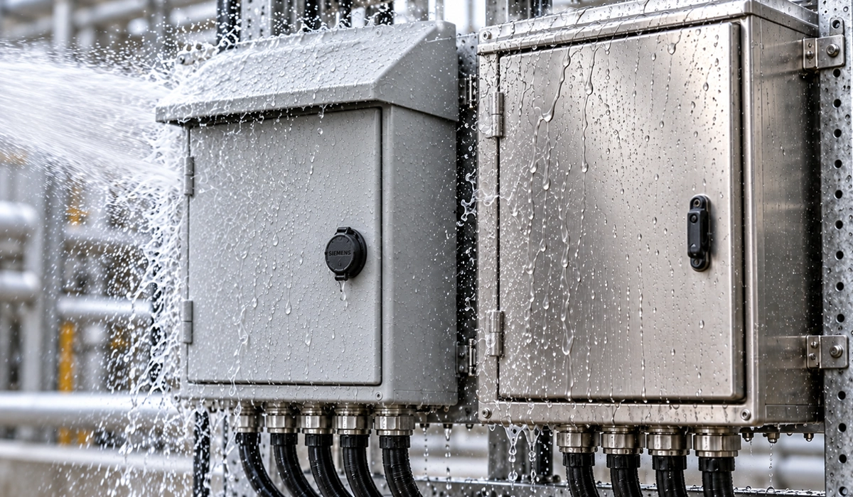
Cable ampacity tables are published under reference installation conditions. In practice, cables are often installed in ways that reduce their ability to dissipate heat — such as being buried in soil, grouped in conduit, or exposed to high ambient temperatures. In these cases, derating factors must be applied to reduce the published ampacity to a safe operating level. The installation environment also determines the required ingress protection rating; for guidance on selecting the appropriate enclosure class, see our comparison of IP vs. NEMA ratings and IK impact protection. For industrial indoor applications specifically, the IP55 vs. NEMA 12 comparison is a useful reference when specifying termination enclosures and junction boxes alongside the cable.
| Installation Condition | Effect on Ampacity | Required Action |
|---|---|---|
| Ambient temp above 30°C | Reduced — cable runs hotter | Apply temperature correction factor |
| Multiple cables in conduit/tray | Reduced — less heat dissipation | Apply grouping derating factor |
| Direct burial in soil | Varies with soil thermal resistivity | Use buried cable ampacity tables |
| Exposed to sunlight (outdoor) | Reduced — solar heating effect | Use UV-resistant cable; apply solar derating |
| In free air (single cable) | Higher ampacity than conduit | Use free-air tables for sizing |
Another factor that is often overlooked during installation design is the concept of pollution degree and overvoltage category, which affects clearance and creepage requirements at cable termination points — particularly in outdoor or contaminated environments.
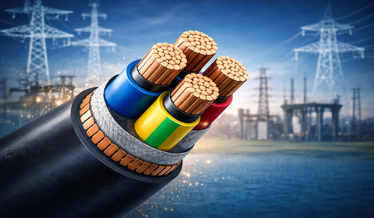
Safety Considerations When Selecting a Three-Phase Power Cable
Beyond sizing, safety compliance is a non-negotiable part of any cable selection. The following points must be addressed in every project:
- Protective Earth (PE) Conductor: Every three-phase cable must include a properly sized PE conductor to provide a fault current return path and prevent electric shock. Correct earthing system design and regular verification are essential — for practical methods, refer to our guide on measuring earth resistance.
- Tight, Correct Connections: Loose terminals cause arcing, localized heating, and fire. Use the correct termination tools and torque values.
- Mechanical Protection: In areas exposed to physical impact, vibration, or rodent activity, use armored cable (SWA — Steel Wire Armored) or install in rigid conduit. This principle also applies to busbar systems — see safety and compliance in busbar manufacturing.
- Arc Flash Hazard: Cable termination work inside energized panels carries arc flash risk. All work should be conducted in accordance with NFPA 70E and IEEE 1584 —consult the arc flash label requirements quick reference guide to ensure proper labeling and PPE selection.
- Environmental Protection: Protect cables against UV radiation, moisture ingress, and chemical exposure using appropriate outer sheath materials and IP-rated enclosures.
- Compliance with Standards: Always design to the applicable standard — IEC 60364, BS 7671 (UK), NEC (USA), DIN VDE (Germany), or the applicable national standard. This ensures cables have passed required thermal and electrical tests.
- Periodic Inspection: After installation, perform visual cable inspections, connection temperature checks using thermal imaging, and earthing continuity verification at regular maintenance intervals.
For the standards that apply across switchgear, cable and busbar together, see the electrical standards guide.
Armored vs. Unarmored Cable: When to Use Each
| Cable Type | Mechanical Protection | Typical Use Cases | Cost |
|---|---|---|---|
| Unarmored (flexible/fixed) | Low — relies on conduit or trunking | Indoor panels, control cabinets, protected routes | Lower |
| SWA (Steel Wire Armored) | High — steel wire protects against crushing | Direct burial, industrial floors, outdoor runs | Higher |
| STA (Steel Tape Armored) | Medium — protection against impact | Fixed underground or duct installations | Medium |
Conclusion
Reliable three-phase cable selection combines accurate electrical calculations with practical installation considerations. Key checks include verifying load current, choosing a cable size that meets ampacity and voltage-drop limits, and applying appropriate derating factors based on temperature, grouping, and installation conditions.
Engineers should also select suitable insulation, provide mechanical protection where needed, size the protective earth conductor correctly, and ensure compliance with relevant standards. Following this approach helps create a safe, efficient, and durable installation.


Rate this article
Choose a rating from 1 to 5 stars.
No ratings yet