


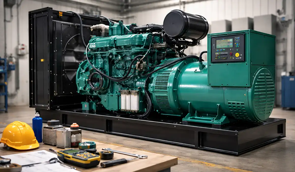





What Is an Electric Generator? Definition and Core Principle
A generator is a machine that converts mechanical energy into electrical energy by means of a magnetic field — specifically, relative motion between a magnetic field and a conductor. In a packaged generator set, that chain runs: prime mover → alternator → (optionally) inverter → output.
Each element has a defined job:
- Prime mover — supplies the mechanical energy. Diesel or gas engine, steam or gas turbine, water turbine, wind rotor.
- Magnetic field — produced by the field winding or by permanent magnets. This is the medium through which energy is converted.
- Alternator — the rotor and stator assembly where the induced voltage appears.
- Inverter — present on inverter generators only. Rectifies the raw AC to DC, then synthesises clean AC at a controlled frequency.
In power plants, generators are turbine-driven. On facilities and job sites they’re packaged as engine-generator sets, where the engine and alternator sit on a common skid with a control panel, governor and enclosure.
Generator or alternator? An alternator is a generator that produces AC. “Generator” is the broader term covering both AC and DC machines. Historically, DC generators (dynamos) used a commutator to rectify mechanically; modern systems use an alternator plus solid-state rectification instead.
How Does an Electric Generator Work?
Faraday’s law states that the EMF induced in a circuit is proportional to the rate of change of magnetic flux through it. Two mechanisms produce that change:
- Motional EMF — a conductor physically moves through a stationary field
- Transformer EMF — the conductor is stationary and the field itself changes
Rotating machines use both, depending on construction. Lenz’s law adds the direction: the induced current opposes the change producing it, which is why a generator under load takes more torque from the prime mover than one running unloaded. That opposition is the mechanical-to-electrical conversion made physical.
Rotor, Stator and Field
Two arrangements exist, and which is which matters:
- Rotating field, stationary armature — the field winding sits on the rotor, output windings on the stator. Standard for AC generators above a few kilowatts, because it avoids passing full output current through slip rings.
- Rotating armature, stationary field — output windings on the rotor, collected via slip rings or a commutator. Used in small machines and DC dynamos.
The air gap between rotor and stator is a critical design dimension: too large and magnetic coupling suffers, too small and thermal expansion or bearing wear risks a rub.
Frequency, Speed and Pole Count
Output frequency on a synchronous generator is fixed by rotor speed and pole count:
f = (P × N) / 120
where f is frequency in Hz, P is the number of poles, and N is speed in rpm.
| Poles | rpm for 60 Hz | rpm for 50 Hz |
|---|---|---|
| 2 | 3600 | 3000 |
| 4 | 1800 | 1500 |
| 6 | 1200 | 1000 |
| 8 | 900 | 750 |
This is why engine-driven gensets run at fixed speed — 1800 rpm is the common four-pole choice at 60 Hz, 1500 rpm at 50 Hz. It’s also why inverter generators can vary engine speed: the raw AC frequency no longer matters because it’s rectified to DC and re-synthesised.
Excitation and the AVR
The field needs current to produce flux, and that current has to change as load changes — otherwise terminal voltage sags on load application and overshoots on rejection.
- Brushless — an exciter alternator plus rotating rectifier on the shaft. No brushes to wear. The common arrangement in modern gensets.
- Permanent magnet (PMG) — a separate PMG supplies the AVR, so excitation survives even when terminal voltage collapses during a fault. This is what lets a set sustain short-circuit current long enough for downstream protection to trip — typically around 300% for 10 seconds.
- Shunt / self-excited — the AVR takes power from the output itself. Cheaper, but short-circuit support is poor.
The AVR senses terminal voltage and adjusts field current to hold the setpoint. If you have selective coordination requirements downstream, the excitation type is not a detail — a shunt-excited set may not sustain enough fault current to trip the breaker you’re relying on.
Types of Electric Generators in Electrical Engineering
When people say “types of electric generators,” they usually mean output form (AC vs DC), portability (inverter portable vs conventional), or application class (standby vs prime vs continuous). Those choices affect power quality, fuel consumption, maintenance, and what standards apply.
A quick reality check: most modern electric infrastructure runs on AC, so AC generators dominate bulk power. DC generators still exist, but mostly in niche roles or as part of systems that immediately convert output using power electronics.
| Type | Output | How it works | Typical use |
|---|---|---|---|
| AC alternator (synchronous) | AC | Rotating field, stationary armature; frequency = (poles × rpm)/120 | Grid generation, facility standby, gensets above a few kW |
| Induction (asynchronous) generator | AC | Driven above synchronous speed; needs external reactive power or capacitors | Small hydro, older wind turbines, co-generation |
| DC dynamo | DC | Commutator mechanically rectifies the internally generated AC | Legacy systems, teaching, some traction applications |
| Inverter generator | AC | AC → rectified to DC → re-synthesised as controlled AC | Sensitive electronics, camping, quiet applications |
| Conventional portable | AC | Fixed engine speed, direct alternator output | Job sites, resistive loads, tools |
| Standby (fixed installation) | AC | Permanently installed, paired with an ATS | Residential and commercial backup |
AC Generators (Synchronous Alternators)
An alternator is essentially a synchronous generator: frequency is tied to rotor speed and pole count, and large-scale systems generally operate on a three-phase configuration. For big units, synchronization to the grid matters — voltage, frequency, and phase must all align before paralleling.
Excitation can be brushless, field-wound, or permanent magnet based, and the AVR adjusts field current to hold voltage as loads swing. That’s why “excitation system” is not trivia — it’s operational stability. Frequency is set by speed and pole count, so an engine-driven set holds constant rpm. For grid paralleling, voltage magnitude, frequency and phase angle must all match before the breaker closes — a synchroscope or synchronising relay handles this. Closing out of phase produces a torque transient that can shear a coupling.
DC Generators (Dynamos)
A dynamo produces DC using a commutator, mechanically rectifying the generated AC inside the machine. Historically important, but less common today because solid-state rectification and DC buses are usually cheaper and more controllable.
You’ll still see DC generator concepts in education, legacy systems, and certain specialized applications, but most modern “DC power” is produced by alternators plus rectifiers.
Synchronous vs Induction Generators
A synchronous generator has its own excitation and can set the system voltage and frequency — it can run islanded. An induction generator has no field winding; it’s an induction machine driven above synchronous speed, drawing its magnetising current from the network it feeds. Simpler and cheaper, but it cannot start or run without either a grid connection or a capacitor bank supplying reactive power. That constraint is why induction generators appear in small hydro and older fixed-speed wind turbines but never in standby applications.
Inverter Generators vs Conventional Portables
An inverter generator typically makes AC, rectifies to DC, then inverts back to controlled AC. The practical benefits are better power quality (lower THD), quieter operation via variable engine speed, and easier paralleling on many models.
Conventional portables can be perfectly fine for resistive loads, but inverter units are often preferred for sensitive electronics because waveform quality and frequency regulation are typically tighter. The trade-off is peak power per dollar: at the same nameplate rating an inverter unit typically costs more and offers less surge headroom than a conventional portable.
Standby Generators (Fixed Installations)
A standby generator is permanently installed and commonly paired with an automatic transfer switch (ATS) so loads switch to generator power during an outage without manual intervention. This is where fuel supply planning and maintenance discipline stop being optional.
For stationary sets, UL 2200 is a key safety standard, and building/code frameworks often require listing for certain applications.
For sizing a standby set to a specific service, see what size generator for 100 amp service.
Key Components of an Electric Generator
| Component | Function |
|---|---|
| Prime mover | Engine or turbine supplying mechanical energy |
| Rotor | Carries the field winding or permanent magnets; rotates with the prime mover |
| Stator | Stationary armature windings where output voltage is induced |
| Exciter | Supplies DC to the field, usually brushless via a shaft-mounted exciter and rotating rectifier |
| AVR | Senses terminal voltage and adjusts excitation to hold the setpoint |
| Governor | Controls prime mover speed, and therefore output frequency |
| Bearings | Support the rotor; the most common mechanical wear item |
| Cooling | Air, water/glycol, or hydrogen on very large machines |
| Enclosure | Weather protection and acoustic attenuation; IP or NEMA rated |
| Control panel | Start/stop logic, protection, alarms, metering, shutdown |
Two of these decide day-to-day behaviour more than anything else. The governor holds frequency and the AVR holds voltage; together they determine how the set responds when a large load is applied or rejected. Poor regulation shows up as nuisance trips on downstream electronics long before it shows up as a generator fault.
Generator Ratings: Standby, Prime, Limited-Time and Continuous (ISO 8528)
These aren’t marketing labels. ISO 8528-1 defines four rating classes, and each carries a specific limit on annual hours and average load factor. Buying the wrong class voids warranty coverage as reliably as it shortens engine life.
| Rating | Annual hours | 24-hour average load factor | Overload capability | Typical use |
|---|---|---|---|---|
| ESP — Emergency Standby Power | Limited (commonly ~200 h) | ≤ 70% of ESP rating | None | Utility backup |
| PRP — Prime Power | Unlimited | ≤ 70% of PRP rating | Typically 10% for 1 h in 12 | Off-grid with variable load |
| LTP — Limited-Time running Power | Up to 500 h | Up to 100% | None | Peak shaving, load curtailment |
| COP — Continuous Operating Power | Unlimited | Up to 100%, constant load | None | Remote power stations, base load |
Individual engine manufacturers may authorise a higher average load factor than ISO specifies — some publish 75% for ESP — so check the specific engine’s published rating rather than assuming the standard minimum.
Why it matters commercially: an ESP-rated 500 kVA set and a PRP-rated 500 kVA set are not the same machine at the same price, and specifying ESP for an application that runs 600 hours a year is a warranty problem waiting to surface.
Power Quality and THD
THD (total harmonic distortion) measures how far a waveform departs from a pure sine. High THD causes additional heating in motors and transformers, and misbehaviour in drives, UPS front ends and switch-mode supplies.
Rough expectations by machine type:
- Inverter generators — typically under 3% THD, because the output is synthesised electronically rather than generated directly
- Conventional portables — commonly in the high single digits to low teens, sometimes worse under light load
- Fixed standby sets with a well-specified alternator — usually under 5% at no load, but the number that matters is THD with your actual non-linear load connected, not the no-load figure on the datasheet
The trap is that the datasheet figure is measured on a linear load. Connect a bank of VFDs and the harmonic currents they draw interact with the alternator’s subtransient reactance, and voltage THD rises well above the published number. If non-linear load is more than roughly a third of the total, specify a lower-reactance alternator or oversize the set.
Selecting a Generator: The Short Version
Five decisions, in order:
- Load audit — running kW and starting kVA, and whether large loads are step-applied or sequenced. Adding nameplate ratings together is how a set that looks adequate on paper collapses on the first motor start.
- Rating class — ESP, PRP, LTP or COP per ISO 8528, matched to expected annual hours.
- Voltage, frequency and phase — single or three-phase, and the pole count that follows from the frequency.
- Environment — ambient temperature and altitude both derate output; enclosure rating and acoustic limits follow the site.
- Fuel — diesel for load acceptance and on-site energy density; natural gas where the utility is reliable and runtime is long; propane where storage life matters.
On motor starting: locked-rotor kVA produces a voltage dip whose depth depends on the alternator’s subtransient reactance and the starting method. Too deep and contactors drop out and drives fault on undervoltage. Soft starters and VFDs reduce inrush substantially and often permit a smaller set — run that comparison before sizing up.
For a full worked load calculation, transfer switch selection and NEC Article 702 requirements, see what size generator for 100 amp service.
Standards for Electric Generators: NEC 445, NFPA 110, UL 2200 and IEC 60034
Article 445 is one of the shortest articles in the NEC, because unlike motors you don’t need to size and protect conductors to a generator. The sections that matter:
- 445.11 Marking — nameplate showing manufacturer, rating, frequency, number of phases, power factor, and whether the neutral is bonded
- 445.12 Overcurrent protection — requirements vary with generator construction and system type
- 445.13 Ampacity of conductors — the ampacity from the generator output terminals to the first distribution device containing overcurrent protection must be not less than 115% of the nameplate current rating. Neutrals may be sized per 220.61; conductors carrying ground-fault current per 250.30(A)
- 445.18 Disconnecting means — and provision to shut down the prime mover
- 445.20 GFCI — required for 125 V, 15 and 20 A receptacles on portable generators
A widely misapplied point on 445.13: it governs the run from the alternator terminals to the first overcurrent device only. Where the set ships with an integral breaker — which most do — that run is inside the package and is the manufacturer’s responsibility. Conductors downstream of that breaker are a feeder, sized normally under Articles 240 and 310. Inspectors and installers regularly apply the 115% rule to the wrong conductors.
NFPA 110 — Emergency Power Supply Systems
NFPA 110 classifies every EPSS on three independent axes, and a compliant specification names all three:
- Level — consequence of failure. Level 1 where failure could cause loss of human life or serious injury; Level 2 where it is less critical to human life.
- Type — maximum permitted time, in seconds, before load is available. Type 10 means power within 10 seconds; Type U is uninterruptible; Type M is manual.
- Class — minimum time in hours the system can run at full load without refuelling. Class 2 is two hours, Class 48 is 48 hours, Class X is a specified other duration.
A hospital emergency system is commonly specified as Level 1, Type 10, Class 48 — which is a complete, testable requirement in a way that “NFPA 110 compliant” alone is not.
NFPA 110 also sets testing obligations: monthly exercise, and annual load testing where the monthly exercise doesn’t reach a defined load threshold, with records retained. Commissioning and recordkeeping are part of the specification, not an afterthought.
NEC Article 445 (Generators)
Article 445 addresses generator installation requirements such as nameplate/marking, overcurrent protection, and disconnecting means, with conductor and protection coordination considerations depending on the system design.
The key specifier move: coordinate the generator, ATS, and downstream protective devices so the installation meets both safety intent and operational behavior — no nuisance trips, no undersized conductors, clear disconnecting means. Three-phase cable selection is central to this coordination.
UL 2200 and IEC 60034
UL 2200 covers stationary engine-generator assemblies as complete systems — the engine, alternator, enclosure, fuel system and controls evaluated together, not as a collection of separately recognised components. Many AHJs require the listing for permanently installed sets, and a set assembled from individually listed parts is not the same thing as a UL 2200 listed assembly.
IEC 60034 is the international series for rotating electrical machines. IEC 60034-1 covers rating and performance, including duty types S1 through S10 and the temperature-rise limits by insulation class. IEC 60034-22 deals specifically with AC generators for reciprocating internal-combustion-engine-driven sets.
ISO 8528 sits alongside these and is the one specifiers most often need — it defines the ESP, PRP, LTP and COP rating classes covered above, plus performance classes G1 to G4 for voltage and frequency regulation.
Generator Maintenance and Reliability
Reliability is built on predictable routines: oil and filters, cooling system checks, battery and charger health, fuel system condition, and periodic exercise under meaningful load. For critical systems, load bank testing and documented maintenance are common expectations.
Common failure modes are rarely mysterious: dead batteries, neglected fuel, coolant issues, and controls that never get exercised until the worst possible moment. Treat maintenance like an operational requirement, not a “nice to have.”
NFPA 110 requires monthly exercise for emergency systems, with annual load testing where monthly running doesn’t reach the load threshold. For non-emergency sets, follow the engine manufacturer’s hour-based schedule.
Generator Safety: Carbon Monoxide, Backfeed and Fire
Carbon monoxide is a serious portable-generator hazard. CPSC guidance is clear: use generators outside only, at least 20 feet from the home, and never in garages, carports, or near openings where exhaust can drift indoors.
Also: avoid backfeeding, use proper transfer equipment, let units cool before refueling, and use CO alarms. Many newer portables advertise CO shutoff features, but that’s a safety layer, not permission to ignore placement rules.
Arc flash hazards are present during generator commissioning and switchgear maintenance. This article serves as a valuable resource for those seeking detailed information on arc flash labeling requirements: Arc Flash Label Requirements – NFPA 70E & IEEE 1584 Quick Reference.


Rate this article
Choose a rating from 1 to 5 stars.
No ratings yet