


Prefer listening? You can play the audio version of the rest of this article below.
What Is a Busbar Scheme and Why Does It Matter?
A busbar scheme is the structural arrangement that defines how circuits connect to the common bus, how power flows through the switchyard or switchgear lineup, and how operating states are changed safely. In practice, Single busbar and double busbar schemes sit at the center of busbar scheme in switchgear design.
The strength of this busbar architecture is simplicity. Protection zones are easier to define, interlocking is lighter, panel count is lower, and the switchgear footprint stays compact compared with a two-bus arrangement. For a comprehensive understanding of busbar types, we highly recommend reviewing this article on busbar power distribution.
That arrangement matters because the bus is not just copper or aluminum conductor. It is the shared node for feeder connection to busbar, transformer bays, and protection zones, so one topology change can alter both operability and risk exposure.
A simpler switching scheme usually means lower capital cost, fewer isolators, and easier training. A more elaborate busbar layout usually means higher switching flexibility in substations, better maintenance access, and less severe outage consequences.
For engineers, the real question is not whether a topology is “better” in the abstract. It is whether the chosen substation bus scheme meets reliability targets, fault performance, maintenance expectations, and budget limits for that specific installation.
For a deeper dive into this topic, see IEEE Standards Association comprehensive guide to Application Guide for AC High-Voltage Circuit Breakers.
Single Busbar Scheme in Switchgear—Architecture and Operation
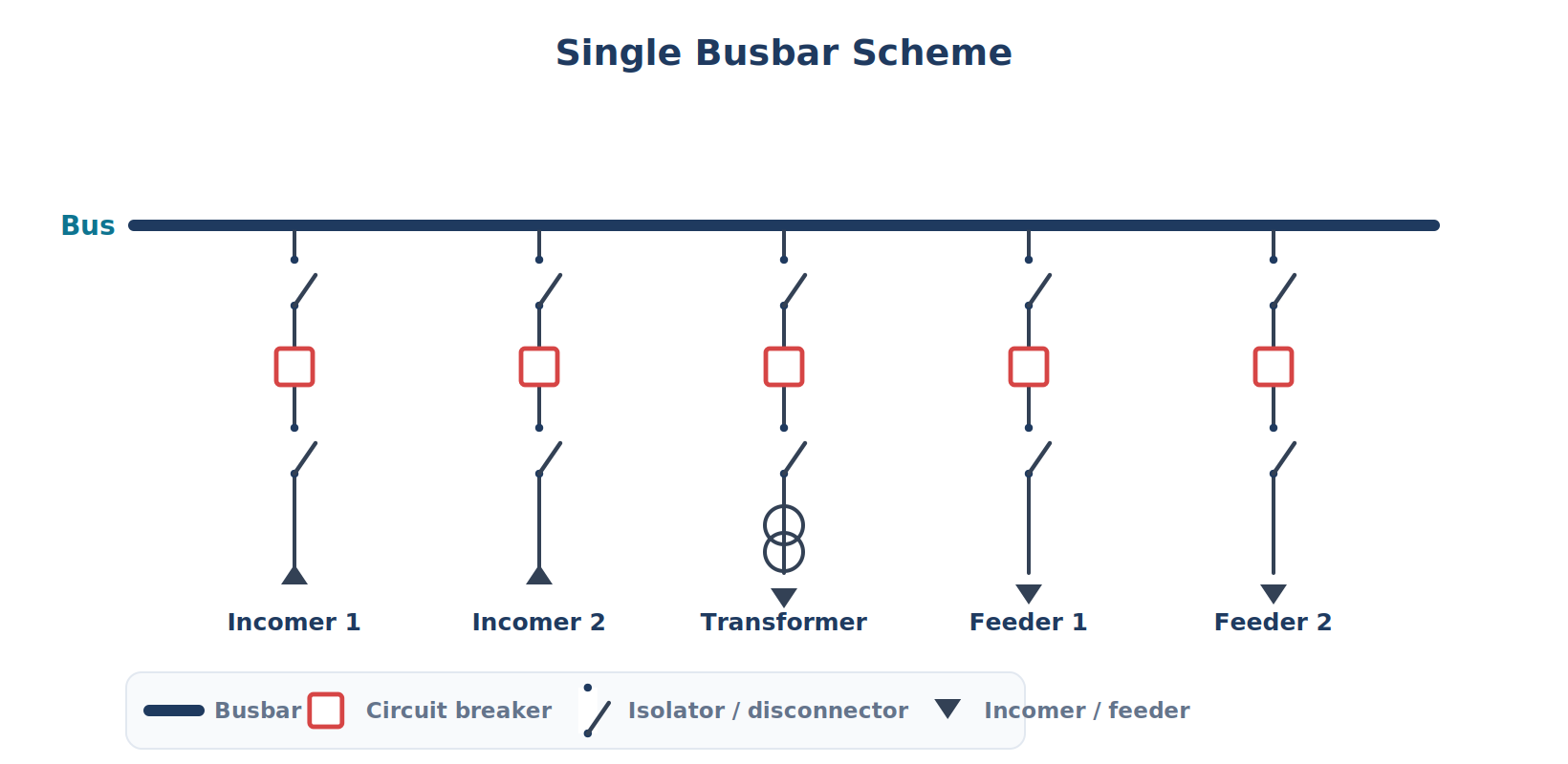
A single bus arrangement is the most direct form of substation busbar arrangement. One common main bus serves all incomers, feeders, and transformer circuits, each connected through its own circuit breaker and isolating devices. This is the classic single busbar configuration substation model.
The reliability of this arrangement also depends on precise busbar manufacturing, where modern bus bar processing machine is used to achieve accurate cutting, punching, and bending of conductors.
In normal operation, every live circuit depends on that same bus. Operators can open one feeder CB for feeder work, but the bus itself remains a single shared point, so bus maintenance is far less flexible than in a dual busbar system.
If the information related to busbar schemes was interesting and informative to you, researching busbar fundamentals can be very engaging.
Its weakness is equally clear: a bus fault can remove all connected circuits at once. That is why the single bus configuration remains attractive in cost-sensitive plants, but less attractive where continuous supply is critical.
Single Busbar with Bus Sectionalization
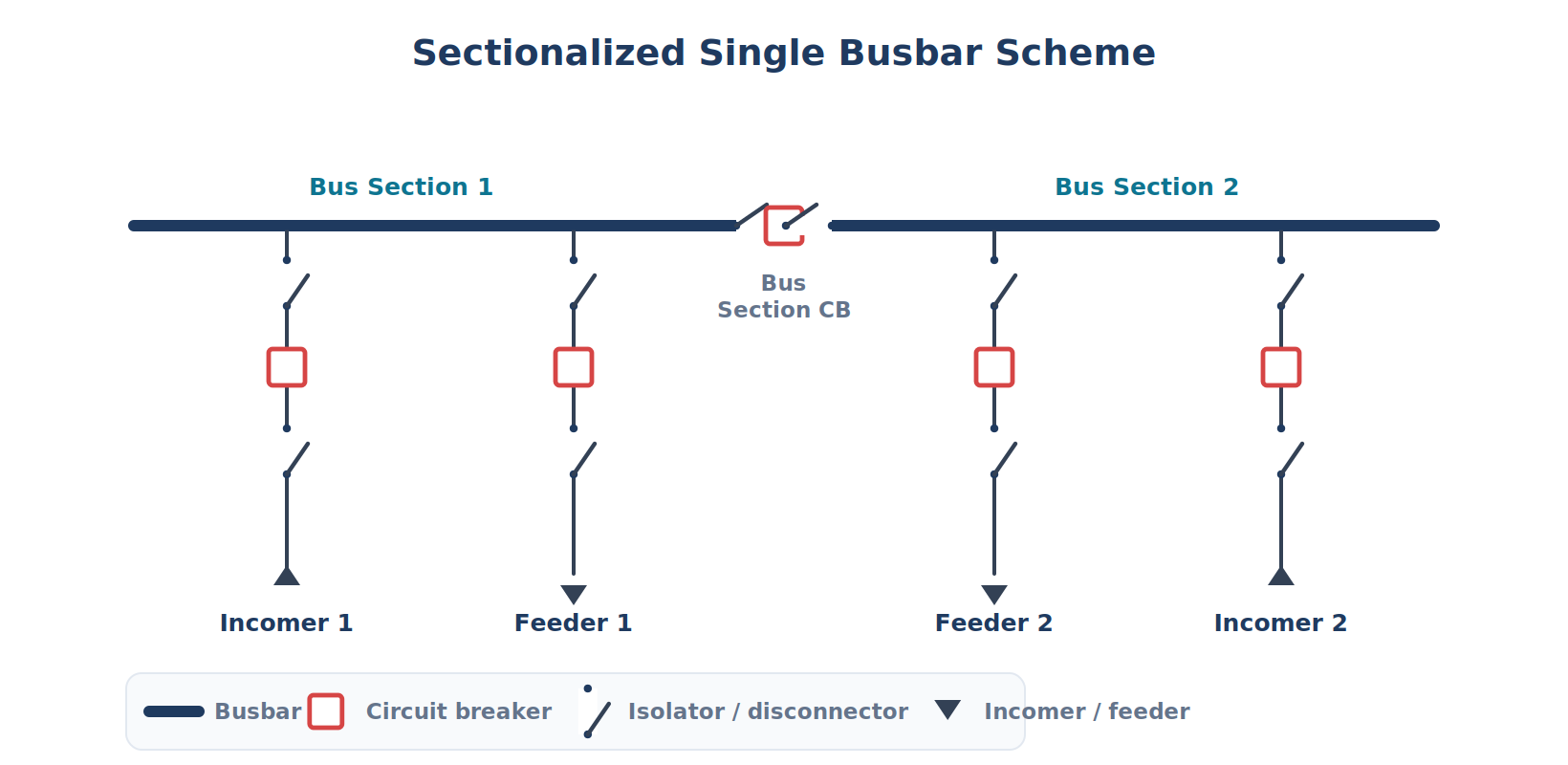
Sectionalization splits one bus into two or more bus sections using a bus-section CB or bus section isolator. That does not create two fully independent buses, but it does reduce the consequence of a fault or maintenance event on one section.
This is why sectionalized single busbar layouts are common when designers want better fault containment and partial continuity without paying for a full double bus arrangement. It is redundancy-lite, not full transfer flexibility. Further exploration of terminal busbar design can be found in the following recommended reading.
For practical examples and case studies, ELECTRA CIGRE’s digital magazine‘s coverage of Service Continuity Guide for HV GIS above 52 kV is worth bookmarking.
Advantages and Limitations of the Single Busbar Scheme
The single busbar scheme advantages and disadvantages are easiest to understand as a trade between simplicity and exposure. The arrangement lowers first cost and operating complexity, but it concentrates risk into one common node.
That trade works well where load criticality is moderate, maintenance windows are acceptable, and outage consequences are manageable. It works poorly where continuous process supply, utility-grade availability, or strict N-1 thinking dominates the design brief.
The table below summarizes the standard engineering view of this topology. It compresses the practical effect of one-bus design on capital cost, maintenance flexibility, and busbar protection scheme exposure.
Learn more about Substation Configuration in this detailed walk-through by National Academies.
| Aspect | Single Busbar Scheme |
|---|---|
| Capital Cost | Low — One Bus, Fewer Isolators, Minimal Interlocking |
| Complexity | Simple — Easy to Operate and Train Staff |
| Maintenance Flexibility | Low — Bus Work Needs a Full or Sectional Outage |
| Fault Impact | High — A Bus Fault Can Trip All Connected Circuits |
| Switching Flexibility | None (Limited with Sectionalization) |
| Space Requirement | Compact — Smallest Footprint |
| Reliability Level | Moderate (Improves with Sectionalization) |
| Typical Application | Distribution, Small/Medium Industrial, Cost-Sensitive Plants |
The key point is not that single bus is “weak.” It is that it is efficient when the design target is economical service, not maximum operational freedom. That distinction matters in every busbar scheme selection criteria review.
Double Busbar Arrangement (Double Bus Bar Scheme)—Architecture and Operation
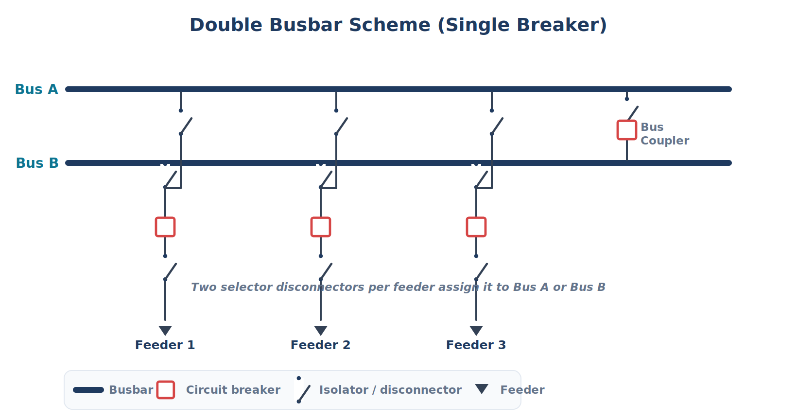
A double bus arrangement uses two separate main buses, often called Bus A and Bus B or Main Bus 1 and Main Bus 2. Each feeder has selector disconnectors so it can be assigned to either bus under controlled switching conditions. This is the basic double busbar arrangement power system model.
In typical operation, feeders are shared across the two buses and the bus coupler manages transfer or coupling between them. ABB’s design guidance describes the double-busbar arrangement with feeders shared between buses and the coupler enabling switching between buses without load interruption.
This gives operators much more freedom than a single bus configuration. One bus can remain energized while the other is isolated for inspection, extension, or repair, which directly improves service continuity and outage planning.
This article serves as a valuable resource for those seeking detailed information on power distribution boards.
The price is greater complexity. A double bus topology needs more disconnectors, more interlocking, more space, and more disciplined operating procedures, especially during transfer sequences and busbar protection zone changes.
Learn more in IEC International Standards guide to AC metal-enclosed switchgear used indoors and outdoors.
Double Bus Single Breaker Scheme—The Standard Double Busbar Configuration
The arrangement described above has a formal name: the double bus single breaker scheme. Each feeder connects through one circuit breaker, but a pair of selector disconnectors lets that feeder be assigned to either Bus A or Bus B. A single bus coupler links the two buses. This is the most common double busbar configuration in MV and HV substations, because it gives strong transfer flexibility at a moderate breaker count.
It’s important not to confuse it with the double breaker double bus (DBDB) scheme, where every feeder has two dedicated breakers — one to each bus. DBDB offers the highest reliability and allows live breaker maintenance, but at the highest cost, so utilities often prefer breaker-and-a-half or the double bus single breaker scheme instead.
| Feature | Double Bus Single Breaker | Double Breaker Double Bus |
|---|---|---|
| Breakers per Feeder | One | Two |
| Cost | Moderate | Highest |
| Feeder Transfer Between Buses | Via Selector Disconnectors | Inherent (Each Feeder on Both Buses) |
| Live Breaker Maintenance | Limited | Yes |
| Typical Use | Most Grid/Industrial Double-Bus Substations | Critical EHV Nodes, Generation Intake |
Bus Coupler—Function and Operational Significance
The clearest answer to how does a bus coupler work in a double busbar arrangement is this: it is the bus-to-bus switching device that links Bus A and Bus B so feeders can be moved, sections can be paralleled when allowed, and one bus can be isolated while the other remains in service. It is not a feeder bay.
Its operational value is huge. Without the bus coupler, a two-bus layout loses much of its flexibility. With it, operators gain controlled transfer capability, better outage management, and more practical maintenance sequencing.
Bus Section vs Bus Coupler: What’s the Difference?
One of the most common points of confusion in substation design is the difference between a bus section (bus sectionalizer) and a bus coupler. They look similar on a one-line — both are a breaker between two lengths of bus — but they do fundamentally different jobs.
A bus section breaker divides one single bus into two segments. Both segments are still part of the same bus. Its purpose is to limit how much of a single-bus scheme is lost during a fault or maintenance — if one section is isolated, the other keeps feeding its circuits. It’s redundancy-lite inside a single-bus layout.
A bus coupler links two separate main buses (Bus A and Bus B) in a double-bus scheme. Its purpose is transfer: it lets feeders move from one bus to the other, allows the two buses to be paralleled during controlled switching, and keeps one bus energized while the other is isolated for repair or extension. A bus coupler consists of a circuit breaker and isolators, and it lets the entire load transfer to the other bus so supply is not interrupted during busbar maintenance.
| Point | Bus Section (Sectionalizer) | Bus Coupler |
|---|---|---|
| What It Connects | Two Segments of the Same Bus | Two Separate Main Buses |
| Scheme It Belongs to | Single Busbar (Sectionalized) | Double Busbar |
| Main Purpose | Limit Outage Extent Within One Bus | Transfer Feeders / Isolate One Bus |
| Redundancy Provided | Partial | Full Transfer Capability |
| Adds a Second Bus? | No | Yes |
Simple rule: a bus section splits one bus; a bus coupler joins two buses. If someone shows you a scheme with a coupler, there are two buses. If it’s a sectionalizer, there is still only one.
Double Main and Transfer Bus Scheme (Main-and-Transfer Variant)
The main and transfer busbar arrangement is a special variant where one bus is normally energized and the second serves as a transfer or reserve bus. GE and the National Academies both describe it as a configuration used to keep a circuit in service while its regular breaker is removed for maintenance.
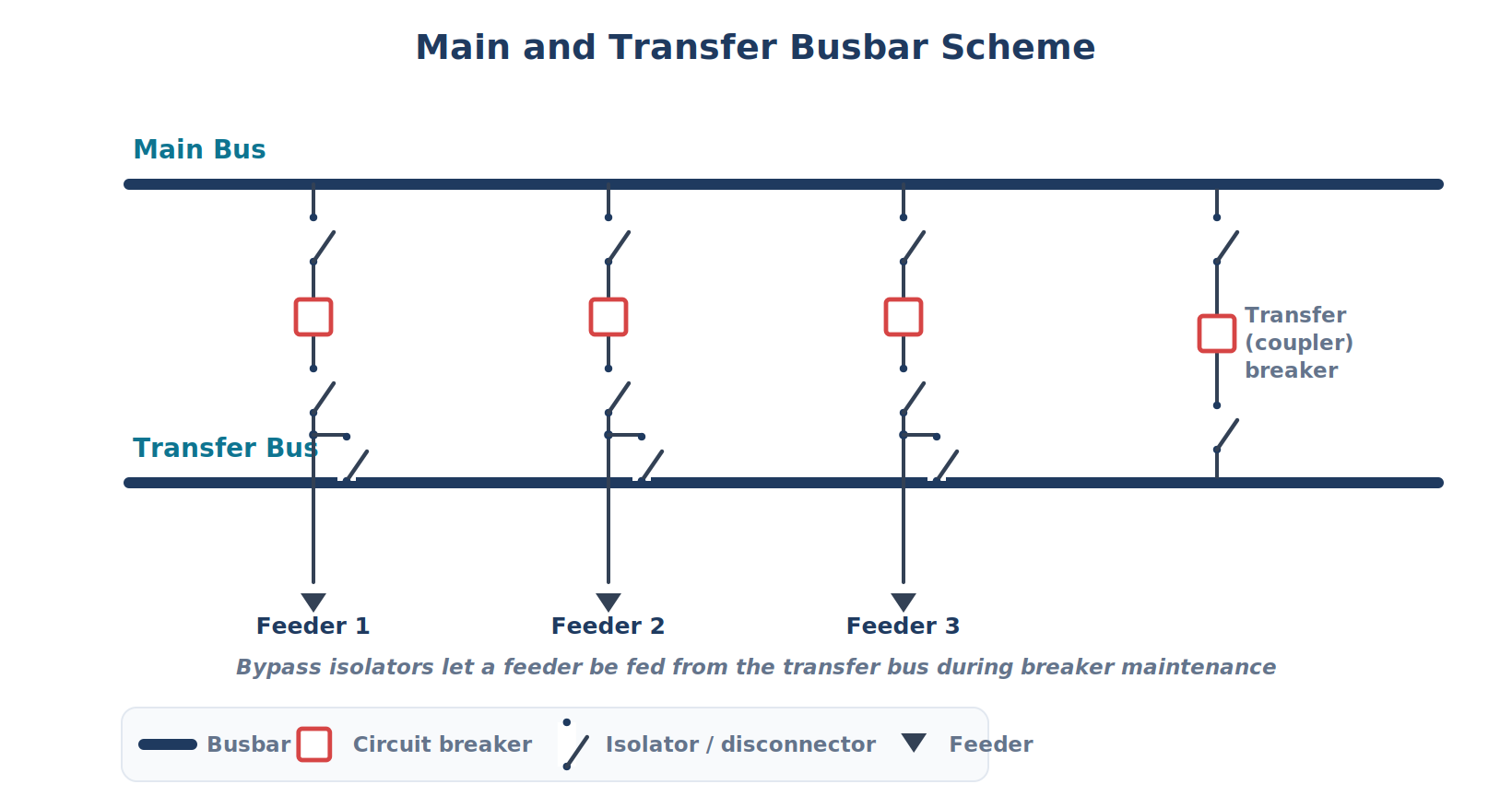
That makes it different from a standard double bus scheme where both main buses may carry normal load simultaneously. Main-and-transfer is more maintenance-oriented; full double bus is more operation-oriented.
Grab the complete Application Note; Bus Differential Protection guide.
Advantages and Limitations of the Double Busbar Scheme
The main advantages of double busbar over single busbar in substations come from separation and transfer capability. A fault on one bus does not automatically remove the whole installation, and planned work can often proceed without a total shutdown.
That benefit becomes more valuable as load criticality rises. Grid substations, power generation auxiliaries, and business-critical process plants gain measurable operational resilience from lower outage exposure and stronger maintenance flexibility.
The downside is engineering complexity. More buses mean more switching states, more interlocks, more disconnector status logic, and more elaborate busbar protection scheme coordination than a single-bus layout requires.
The summary below reflects the usual industry trade-off between higher capital cost and higher service continuity. That is the real reason the topology is favored in critical substations rather than everywhere.
If the details you gathered about double busbar schemes were interesting and insightful, you may find diving deeper into busbar sizing methods equally captivating.
| Aspect | Double Busbar Scheme |
|---|---|
| Capital Cost | Higher — requires additional bus, isolators, and coupler |
| Complexity | More complex switching sequences required |
| Maintenance Flexibility | High — maintenance possible without full supply interruption |
| Fault Impact | Lower — fault contained to one bus; other bus remains live |
| Switching Flexibility | High — feeders can be allocated to either bus |
| Typical Application | Transmission substations, grid substations, critical infrastructure |
| Reliability Level | High |
Single Busbar vs. Double Busbar—Direct Comparison
This is the section most readers actually need, because what is the difference between single and double busbar schemes comes down to how much redundancy, operability, and service continuity the design must buy. In practical terms, Single busbar and double busbar schemes differ far more in outage behavior than in drawing appearance.
Single bus is cheaper, simpler, and more compact. Double bus is costlier, larger, and more complex, but it gives stronger switching flexibility in substations and better isolation of maintenance or fault events.
This is also the heart of single vs double busbar switching analysis: one scheme minimizes equipment count, while the other minimizes operational constraint. Neither wins unless the project criteria are clear.
For a fast busbar scheme comparison for high voltage substations, the table below is the cleanest design-screening tool. It aligns with the way utilities and OEMs typically discuss bus topology choices.
Access the Review of substation busbar component reliability document.
| Comparison Criterion | Single Busbar | Double Busbar |
|---|---|---|
| Number of Busbars | One | Two |
| Bus Coupler Required | No | Yes |
| Feeder Isolation for Maintenance | Full outage needed | Possible without full outage |
| Busbar Fault Consequence | All circuits lost | One bus lost; other remains live |
| Load Transfer Capability | None or limited with sectionalization | Full transfer between buses |
| Protection Complexity | Simple | More complex |
| Space Requirement | Compact | Larger footprint |
| Cost | Lower | Higher |
| Best Suited For | Distribution, small industrial | Transmission, critical loads |
How to Choose Between Single and Double Busbar Schemes
The correct choice starts with load criticality. If an outage can stop a process line, interrupt a utility node, or damage a zero-downtime operation, the answer usually moves away from single bus and toward a more flexible topology. This is the first real busbar scheme selection criteria checkpoint.
The second checkpoint is reliability target. A plant that accepts planned shutdowns may tolerate single bus or sectionalized single bus. A station that must keep service during repair, extension, or frequent switching often justifies the extra bus, selectors, and coupler.
For a comprehensive understanding of future busbar developments, we highly recommend reviewing this article on busbar system trends.
The third checkpoint is fault level and protection design. Short-circuit duties, calculated under IEC 60909 methods, affect equipment rating, protection coordination, and the practicality of more advanced arrangements. High performance requirements usually make topology discussion inseparable from fault-duty discussion.
The fourth checkpoint is maintenance philosophy. If bus inspection, bay extension, or equipment replacement must happen with minimal interruption, double bus or main-and-transfer logic becomes more attractive than a one-bus arrangement.
The fifth checkpoint is economics over the full lifecycle. Low service continuity requirements tend to support easy standardized solutions, while high continuity requirements push the design toward complex customized solutions with higher cost but better operating freedom.
Download the full IEC 61936-1 — installation design and erection requirements above 1 kV AC document.
Typical Applications by Industry and Voltage Level
Actual deployment follows consequence, not fashion. Residential and light commercial distribution usually favors the simple bus topology because cost and compactness matter more than live transfer capability.
Industrial MV switchgear often lands in the middle. Many plants use sectionalized single bus layouts to balance moderate reliability needs against budget and footprint constraints.
As voltage level and criticality rises, the decision shifts. Utility substations, data centers, and high-demand industrial systems increasingly prefer double busbar or related high-continuity arrangements.
If the information on busbar applications was engaging and informative for you, gathering more knowledge about ground bus bar could be very exciting.
That is why when to use double busbar scheme in power system design is usually answered with one phrase: use it when interruption cost, maintenance frequency, or system importance makes operational flexibility worth paying for.
| Application | Typical Busbar Scheme | Reason |
|---|---|---|
| Residential / small commercial distribution | Single busbar | Low criticality, cost sensitivity |
| Industrial plant MV switchgear | Single busbar (sectionalized) | Moderate reliability, cost balance |
| Grid substation 33kV – 132kV | Double busbar | High reliability, maintenance flexibility |
| Transmission substation 220kV+ | Double busbar with bus coupler | Maximum flexibility, N-1 criteria |
| Power generation plant auxiliary bus | Double busbar | Critical continuous supply |
| Data center medium voltage intake | Double busbar | Zero-downtime requirement |
Conclusion
In the end, Single busbar and double busbar schemes are not competing buzzwords. They are two different answers to the same engineering problem: how to balance cost, reliability, protection complexity, and maintenance freedom in a real installation.
Single bus is usually the right answer where compactness, simplicity, and lower CAPEX dominate. Double bus is usually the right answer where outage consequence, maintenance continuity, and switching flexibility in substations dominate.
A sectionalized one-bus scheme can narrow the gap, but it does not fully replace a true two-bus arrangement. That distinction is one of the most important decision boundaries in substation and switchgear design.
For most projects, the smartest workflow is simple: define critical loads, calculate fault duties, decide acceptable outage behavior, and then select the bus topology that satisfies those targets with the lowest lifecycle penalty. Further exploration of power factor correction can be found in the following recommended reading.


At what point do the reliability and maintenance benefits of a double-busbar scheme justify its higher cost, larger footprint, and more complex protection system compared with a sectionalized single-busbar arrangement?