


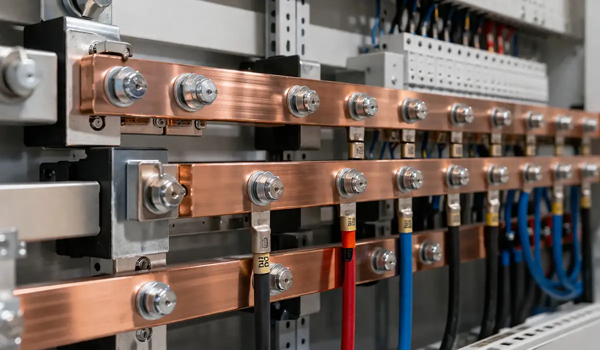





Many electrical designers prefer terminal bus bars for high-current distribution because they reduce resistance and heat rise compared with bundled cables. In contrast with terminal blocks (more on that soon), a bus bar offers a shared potential across all its connection points, which makes them ideal for power distribution rather than isolated circuit terminations. You’ll see them in industrial cabinets where compact footprints and high currents matter, or in marine and renewable energy applications where corrosion resistance and serviceability are essential. This guide walks through what bus bars are, how they differ from terminal blocks, when to use copper vs aluminum, how to size them, and what standards like IEC 61439 and UL 508A mean for your design.
Further exploration of Power Distribution Systems can be found in the following recommended reading.
What Is a Terminal Bus Bar and How Does It Work?
A terminal bus bar is a rigid conductor — normally a flat rectangular bar of high-conductivity copper or electrical-grade aluminium — that is drilled or fitted with studs so multiple conductors can be bolted to it. Every connection point on the bar sits at the same voltage, which is what separates a bus bar from a row of individual terminals. Current arrives from one main feed and leaves through several branch circuits, all sharing one low-resistance path.
The word “terminal” in the name matters. It signals that the bar is a termination point for field conductors, not a long-distance distribution run. A terminal busbar sits inside the enclosure, close to the incoming supply, and its whole job is to turn one large conductor into many smaller ones cleanly. Utility substation bus structures do the same thing electrically, but at a completely different physical scale and under a different standards family.
Three things make the arrangement work well. First, the bar’s cross-section is chosen so the current density stays low enough to keep the temperature rise within limits. Second, the bolted joints are prepared and torqued so contact resistance stays in the microhm range. Third, the bar is mounted on insulating standoffs and shrouded, because a bare bar carrying 400 A is a serious hazard during live maintenance. Get those three right and a terminal bus bar will outlast the panel around it.
Terminal Bus Bar vs Terminal Block: Which One Does Your Panel Need?
At a glance the two look alike: rows of connection points bolted inside a panel. Electrically they are opposites. A terminal block keeps every circuit separate; a terminal bus bar deliberately ties every circuit to the same node.
| Feature | Terminal Bus Bar | Terminal Block |
|---|---|---|
| Function | Distributes power from one source to many points at a common potential | Terminates and connects individual conductors, each circuit kept separate |
| Typical current | High — tens to thousands of amps | Low to medium, usually under 200 A per terminal |
| Isolation | All connection points share one node | Each terminal is isolated unless deliberately jumpered |
| Insulation | Usually bare metal; needs shrouds, covers or an enclosure | Insulated housing built in |
| Mounting | Bolted to insulating standoffs or busbar supports | Clips onto DIN rail |
| Flexibility | Fixed once drilled and installed | Modular; blocks added or removed easily |
| Best for | Main feeds, distribution nodes, earth and neutral collection | Control wiring, field terminations, frequent changes |
The decision is rarely either/or. Most modern panels use a hybrid layout: a terminal bus bar carries the main incoming feed and the heavy branch distribution, while DIN-rail terminal blocks handle control circuits, instrumentation and anything likely to be re-landed during commissioning. That split gives you low impedance where the current is, and modularity where the changes are.
One point often missed — a terminal block can behave like a bus bar if it is a distribution-style block with an internal jumper bar or an insertion bridge fitted across several poles. That is a legitimate low-current solution, but it does not give you the thermal performance or the fault-current withstand of a solid bar. Above roughly 200 A, the bar wins. For panels that also need movement or vibration tolerance at the connection, laminated flexible busbar offers a third option between rigid bar and cable.
Types of Busbar Terminal Used in Electrical Panels
“Busbar terminal” covers several physically different products, and buying the wrong one is a common cause of rework. These are the types you will actually specify:
- Drilled flat bar. Plain copper or aluminium bar with a hole pattern matched to your lug sizes. The most flexible and the cheapest per amp, but you must drill, deburr and shroud it yourself.
- Stud-type bus bar. A bar fitted with threaded studs, usually M6 to M10, so ring lugs drop straight on. Common in marine, vehicle and battery systems, almost always tinned copper with a clear insulating cover.
- Insulated power distribution block. A moulded housing with one large input terminal and several smaller outputs. Finger-safe out of the box, UL-listed as a component, and the easiest route to a compliant panel — but fixed in configuration and limited in current.
- DIN-rail comb busbar. A pin or fork bar that clips across the terminals of adjacent MCBs to feed them from one supply. Fast to install, but rated for the comb’s own current, not the incoming feed.
- Screw-clamp busbar terminal block. A hybrid: a shared bar inside an insulated body, with screw or spring clamps instead of bolts. Good for 20–125 A control and lighting distribution.
- Earth and neutral bars. Functionally the same hardware, but sized and installed under different rules — the sizing and bonding rules for a ground bus bar follow NEC Table 250.122 rather than load current, which catches out designers who assume one bar type fits all.
The selection logic is simple. Below about 125 A with a fixed circuit count, an insulated distribution block saves labour and simplifies compliance. Above that, or where the layout will change, a drilled or stud bar gives you the current capacity and the freedom to re-drill later. Marine and DC battery systems almost always go stud-type, because ring lugs on studs survive vibration far better than screw clamps.
Bus Bar in an Electrical Panel: Where the Terminal Bar Sits
Inside a typical low-voltage panel, the terminal bus bar sits immediately downstream of the main disconnect or main breaker. The incoming cable lands on the bar, and the bar feeds the branch devices — breaker line terminals, contactor inputs, motor starter feeds — through short, individually sized conductors.
That position drives three design constraints. The bar must withstand the full prospective fault current at the incoming point, not just the load current, because there is no protective device between it and the supply. It must respect the spacing and clearance rules for the whole assembly, since it is usually the most exposed live metal in the enclosure. And it must be accessible for torque checks without dismantling the panel, because bolted joints are the first thing a thermographic survey looks at.
A separate earth bar and neutral bar normally run alongside the phase bars, mounted on the enclosure gland plate or the rear panel. Keeping them physically separated and clearly labelled avoids the most common inspection failure: neutral and earth bonded at a point where the installation rules do not allow it.
This section covers the terminal bar specifically. If you need the wider picture — busbar arrangements across a full switchboard, vertical and horizontal distribution, tap-off systems and panel-level architecture — that is covered in the guide to busbar function, types and sizing across a complete electrical panel.
Where Terminal Bus Bars Are Used Beyond the Panel
Outside the industrial control panel, terminal bus bars turn up wherever many circuits must share one supply:
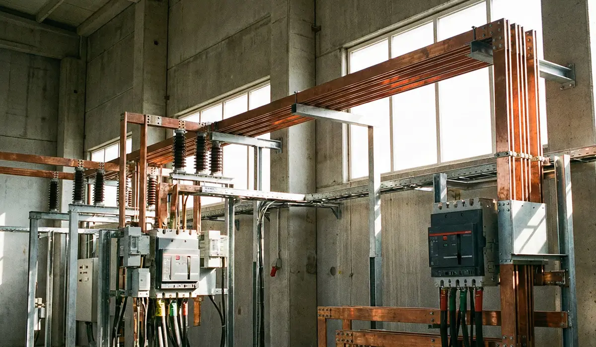
- Switchgear and distribution boards — feeding multiple outgoing ways from a single incomer, in both LV and MV assemblies.
- Marine and vehicle systems — deck power, battery banks and DC distribution, almost always tinned copper stud bars with covers, because salt air destroys bare copper and vibration loosens screw clamps.
- Solar PV combiners and battery energy storage — string inputs and inverter outputs converge on a common bar rather than a nest of cable splices.
- Data centre and UPS distribution — where the load is continuous and every extra milliohm shows up on the electricity bill.
- Grounding and bonding systems — tying enclosure, cable armour, rack and equipment earths to a single reference point.
A practical example shows the benefit. In a factory control panel retrofit, twelve separate 35 mm² cable terminations were consolidated onto a single 300 A tinned-copper terminal bus bar with a snap-on shroud. Wiring time dropped by roughly half, the panel ran measurably cooler under the same load because twelve high-resistance lug joints became one prepared bolted interface, and the next contractor could actually trace the circuits.
Terminal Bus Bar Standards: IEC 61439, UL 508A and UL 1059
A terminal bus bar is never certified on its own. It is certified as part of an assembly, and the assembly standard sets the rules the bar must satisfy.
- IEC 61439-1 / -2 (low-voltage assemblies). The global reference for panels up to 1000 V AC. It governs design verification, temperature-rise limits, short-circuit withstand (Icw and Ipk), clearances and creepage. Verification can be by test, by calculation, or by comparison with a verified reference design. ABB’s guidance on building an assembly to IEC 61439 Parts 1 and 2 is the clearest free explanation of how the verification routes work in practice.
- UL 508A (industrial control panels). The North American equivalent for panels at 600 V or less. It sets spacing tables, wiring methods, marking requirements and the SCCR calculation method in Supplement SB. NEC Article 409 then requires the resulting short-circuit current rating to be marked on the nameplate and to equal or exceed the available fault current at the installation point. The detail of that process is covered in the UL 508A compliance requirements for industrial control panels.
- UL 1059 (terminal blocks). Applies to the blocks rather than the bar, but it defines the insulation, spacing and marking expectations that inspectors carry over to any mixed bar-and-block layout.
The practical consequence: if you substitute a bus bar outside the configuration your panel was verified in — different cross-section, different support spacing, different bar arrangement — you have invalidated the verification. Any change to the bar is a change to the assembly.
Busbar Design Rules: Spacing, Creepage and Clearance
Busbar design begins with two distances that are often confused. Clearance is the shortest distance through air between two conductive parts. Creepage is the shortest distance along the surface of the insulation between them. Clearance is driven by the impulse withstand voltage and altitude; creepage is driven by the working voltage, the pollution degree of the environment, and the comparative tracking index of the insulating material.
Under IEC 61439-1 the values come from Table 1 for clearances and Table 2 for creepage. Under UL 508A the spacings sit in Table 10.1 and 10.1A for branch and control circuits and Table 10.2 for feeder circuits, and they distinguish between spacing to other live parts, spacing to grounded dead metal, and spacing at field wiring terminals. The two systems do not produce identical numbers, so a panel destined for both markets must be designed to whichever is stricter at each point.
Two practical notes save redesign. First, an insulating barrier between phases lets you meet the requirement with less physical separation, which is often the only way to fit three bars into a shallow enclosure. Second, spacing at the field wiring terminal is usually the tightest constraint on the whole bar, because the installer’s lug and the bare conductor tail extend beyond the bar itself. Design for the lug that will actually be fitted, not for the bare bar.
Terminal Bus Bar Sizing: Current, Temperature Rise and Cross-Section
Sizing is a thermal problem before it is an electrical one. The bar is not limited by how much current it can physically carry; it is limited by how hot it gets doing so. Work through it in this order:
- Establish the continuous design current. Sum every branch fed by the bar, apply diversity where it is genuinely justified, then add margin for expansion. Panels grow.
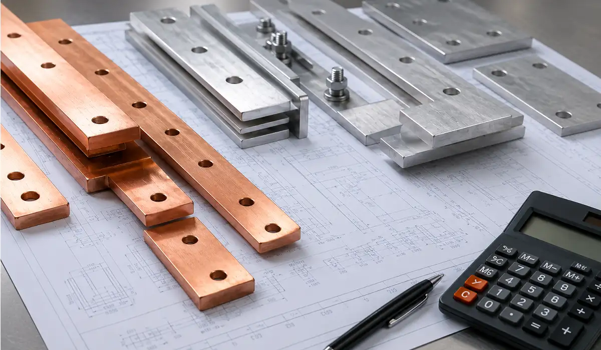
- Choose the material. Copper gives you the smallest cross-section and the easiest joints. Aluminium gives you lower weight and lower cost at a larger size. The trade-off is set out in the next section.
- Select cross-section against the temperature-rise limit. This is where IEC 61439-1 Table 6 applies — and it is widely misquoted. Terminals for external insulated conductors are capped at 70 K, because the cable insulation at the joint fails long before the copper does. Busbars and conductors themselves have no single number in Table 6; they are limited by the mechanical strength of the conductor, the effect on adjacent equipment, the limits of any insulating material in contact with them, and the treatment of the contact surfaces. Footnote (g) then sets an absolute ceiling: assuming every other criterion is met, bare copper busbars must not exceed 105 K rise, which is roughly the point where copper begins to anneal. All of these are referenced to a mean ambient of up to 35 °C. In a 35 °C panel, that 105 K ceiling means a bar surface of 140 °C — a number no sensible designer would run to. Most specifications target 50–70 K.
- Derate for the real installation. Published ampacity tables assume a single bar, horizontally mounted, in free air. An enclosed panel at 45 °C internal ambient, with three bars stacked at close centres, will carry substantially less. Derate for ambient, enclosure, and bar grouping before you commit.
- Verify short-circuit withstand. The bar and its supports must survive the prospective fault current for the declared duration — commonly 1 second — without permanent deformation. Support spacing matters as much as cross-section here, because the electromagnetic force between parallel bars during a fault is what bends them.
The full method, including the ampacity tables for copper and aluminium at 50 K and 70 K rise, is worked through in the guide to busbar sizing by current and temperature rise.
Copper vs Aluminium Terminal Bus Bars: Which to Specify
Copper is the default for terminal bus bars, and for good reasons beyond conductivity. It is harder, so it resists damage during installation. It is stiffer, so it needs fewer supports for the same span. And it forms a far less troublesome surface oxide, which makes reliable bolted joints much easier to achieve.
Electrical-grade aluminium runs at about 61% IACS against copper’s 100% reference, so an aluminium bar needs roughly 1.5 to 1.6 times the cross-section to carry the same current at the same temperature rise. What you get back is weight and cost: aluminium is around one third the density of copper, which is why it dominates long distribution runs and weight-sensitive installations.
For terminal bars specifically, copper usually wins. Terminal bars are short, so the material saving is small, while the joint count is high, and aluminium joints are where the trouble starts. Aluminium forms a hard, insulating oxide within seconds of being cleaned, so every joint needs abrasion under an oxide-inhibiting compound and Belleville washers to hold pressure as the metal creeps.
Two rules if you do use aluminium. Never bolt aluminium directly to copper in a humid environment — use a bimetallic transition plate or tin-plate one side, or galvanic corrosion will eat the joint. And in marine or coastal installations, specify tinned copper regardless of cost; bare aluminium in salt air is a maintenance liability.
Busbar Wiring and Termination: Torque, Contact Pressure and Lugs
Busbar wiring fails at the joints, not in the middle of the bar. Almost every hot spot found on a thermographic survey is a bolted connection, and the cause is nearly always contact pressure that was wrong on day one or was lost to thermal cycling afterwards.
Contact pressure is the real target, not torque. Torque is only the means of achieving it. The Copper Development Association’s Copper for Busbars design and installation guidance recommends never going below 7 N/mm² of contact pressure, prefers above 10 N/mm², and notes that beyond about 30 N/mm² there is little further reduction in contact resistance. That upper plateau is important: over-torquing does not buy you a better joint, it buys you a deformed bar and a stripped thread.
Indicative torque figures for steel bolts into clean copper, dry threads:
| Bolt Size | Typical Torque Range |
|---|---|
| M6 | 7–10 N·m |
| M8 | 15–20 N·m |
| M10 | 28–40 N·m |
| M12 | 45–70 N·m |
Treat these as a sanity check only. The component manufacturer’s datasheet always governs, and lubricated threads reach a much higher clamping force at the same torque setting than dry ones — so you must know which condition the specified value assumes.
Joint preparation matters more than overlap area. Current crosses the joint almost entirely in the compressed region directly under the washers, not across the full overlap. Widening the overlap without raising contact pressure adds copper and weight and achieves nothing electrically. Before assembly, abrade both mating faces to remove oxide, wipe clean, and bolt up promptly. Place the holes in line along the joint rather than staggered — offset holes force the current to detour and raise resistance.
Hardware details that decide joint life:
- Use thick, non-deforming washers to spread load, and Belleville (conical spring) washers to maintain pressure as the metals creep and cycle.
- One ring lug per stud where possible. Stacked lugs need the torque rechecked after the first thermal cycle.
- Never mix copper and aluminium at a joint without a bimetallic transition or plating.
- A warped or twisted bar cannot be fixed with torque; it will contact unevenly and hot-spot regardless. Bars should arrive flat, which is a function of how they were cut, punched and bent during fabrication.
On maintenance, current practice has moved. Blanket annual retorquing of every connection is falling out of favour, because breaking and remaking a sound joint can leave it worse than before. The modern approach is periodic thermographic inspection, with intervention triggered by findings — and when a joint is found hot, full disassembly and surface preparation, not just a nudge on the wrench.
Terminal Bus Bar Installation and Safety Best Practices
Design decides whether the bar can work. Installation decides whether it does.
- Mount on insulating standoffs rated for the fault duty. The supports carry the electromagnetic force during a short circuit, not just the weight. Support spacing is a short-circuit calculation, not a convenience choice.
- Shroud everything reachable. Snap-on covers, phase barriers and end caps prevent contact during live work and stop dropped tools bridging phases. This is the single cheapest risk reduction available.
- Label every connection at the bar, not only at the far end. A bar with twelve identical lugs and no markings turns every future fault-find into guesswork.
- Keep high-current runs short and direct, and keep the loop area small. Long parallel runs with wide separation increase inductance and generate larger mechanical forces under fault.
- Record the as-built torque values. A commissioning record gives the next engineer a baseline to compare against, which is what turns a thermographic survey into a decision rather than an opinion.
- Leave working room. If a torque wrench cannot reach the bolt without removing three devices, the joint will not be checked again for the life of the panel.
Common Terminal Bus Bar Failures and How to Catch Them Early
cross-section, or corrosion at dissimilar metal junctions. Designing and testing per IEC 61439 design verification principles reduces these risks and ensures both safety and longevity.
NEW (complete section body)
Terminal bus bars fail in a small number of predictable ways, and every one of them is visible on a thermal camera before it becomes an outage.
- Loss of contact pressure. Thermal cycling relaxes the bolt, contact resistance climbs, the joint runs hotter, and the cycle accelerates. This is the most common failure by a wide margin, and Belleville washers are the cheapest defence.
- Undersized cross-section. Usually caused by using a free-air ampacity table for an enclosed, densely packed panel. The bar is technically rated but never derated.
- Galvanic corrosion at dissimilar-metal joints. Copper to aluminium without a transition, or bare bar in a humid or coastal environment.
- Surface contamination. Oxide, paint overspray or plating damage under the washer. The joint looks perfect and reads badly.
- Support failure under fault. The bar survives the current but the standoffs do not survive the force, and the bars deform into each other.
When you review a supplier’s datasheet, check what the current rating actually assumes: the ambient temperature, whether the bar was tested enclosed or in free air, and the mounting orientation. A rating without those conditions stated is not a rating. Then check that short-circuit withstand data exists for the support arrangement you intend to use, and that torque values are given for the plating and bolt material you have specified.
Choosing the Right Terminal Bus Bar
A terminal bus bar is a simple component with a narrow margin for error. Get the cross-section, the joint preparation and the shrouding right and it will outlast everything around it. Get the temperature-rise assumption wrong — or quote the 70 K terminal limit as if it applied to the bar itself — and you will build a panel that passes inspection and runs hot for twenty years.
The sequence that works: establish the real continuous current with margin, choose copper unless weight or cost genuinely forces aluminium, size against a target rise of 50–70 K after derating for the actual enclosure, verify short-circuit withstand for the support arrangement you will really use, and treat every bolted joint as a contact-pressure problem rather than a torque number.
Panels also change. Circuits get added, devices get swapped, and the bar you install today will be re-drilled by someone else. Leaving spare hole positions, accessible bolt heads and honest labelling costs almost nothing now and saves a great deal later.
For manufacturers producing terminal bars in volume, joint quality starts at the fabrication stage — flat bars, clean holes and consistent bend radii are what make a torqued joint behave predictably. PAYAPRESS builds CNC busbar cutting, punching and bending machines for exactly that work.



Rate this article
Choose a rating from 1 to 5 stars.
No ratings yet