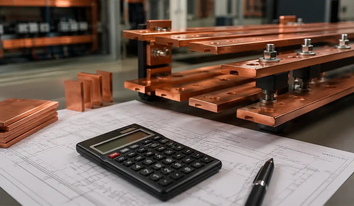
Category: Electrical Busbars & Power Distribution Systems

Copper Busbar Calculator: Complete Guide to Current Carrying Capacity

A copper busbar calculator is an essential tool for electrical engineers and panel builders who must size conductors accurately before committing to a switchgear or distribution board design. Copper busbars — rigid, high-conductivity copper conductors used in switchgear assemblies, distribution boards, substations, motor control centres, and industrial power systems — must carry continuous current without exceeding safe temperature limits while simultaneously withstanding prospective fault currents. An incorrectly sized busbar introduces serious risk: overheating, insulation failure, fire hazard, and unplanned system downtime.

This guide combines practical calculation methodology, reference ampacity tables, derating guidance, and standards compliance into a single authoritative resource. Whether performing manual calculations or using an embedded calculator tool, the sections below cover every variable that governs copper busbar design: continuous current capacity (ampacity), temperature rise, derating factors for real-world installation conditions, and short circuit withstand rating.

Read More »
Busbar Trucking Systems

Busbar Trunking Systems: A Complete Technical Overview

Modern facilities need distribution that is dense, modular, and easier to modify than parallel cable sets. This Busbar Trunking Systems Overview explains why prefabricated busway is often preferred where current is high, space is limited, and future load changes are expected.

You will see how a busbar duct system works, which construction types exist, what ratings and components matter, how design and installation are handled, and where busbar trunking outperforms conventional cable distribution over the full project lifecycle.

Read More »
Busbars in MV Switchgear

Busbars in MV Switchgear: Why Sizing and Fabrication Errors Lead to Thermal Failures and Costly Panel Rework

Busbars in MV switchgear carry and distribute current across every compartment, so their sizing, material, and fabrication quality decide panel thermal performance and fault survivability.

Most failures trace to upstream errors — a specification gap, the wrong copper grade, or loose fabrication tolerances — and they hide until inspection, a thermal event, or a fault. This guide explains the two-calculation sizing rule and the precision fabrication that cut joint temperature rise and pre-FAT rework, covering insulation, IEC standards, and joint quality.

Read More »
LV Switchgear Panels

Busbars in LV Switchgear Panels: Design, Function, and Safety Considerations

Busbars are the main conductive backbone of LV switchgear panels, distributing power from incoming feeders to outgoing circuits and components. Made of copper or aluminum, they are sized based on rated current, short-circuit withstand capability, and thermal performance to minimize voltage drop and overheating. Proper bracing, clearances, and insulation are essential to handle fault-condition stresses and prevent arc flash or phase-to-phase/ground faults. Color-coding and standard-compliant labeling (e.g., IEC 61439) further enhance safety by ensuring correct phase identification during installation and maintenance, making busbar design critical to the overall reliability and safety of the panel.
This guide takes an engineering view of how these conductors are designed, sized, installed, and maintained. It covers current-carrying capacity, short-circuit withstand, material choice, supports, clearances, and the standards that govern verification — IEC 61439 and UL 508A. The promise is concrete: size to the IEC 61439-1 temperature-rise limits and the fault duty, brace for the peak electrodynamics force, and you remove most in-service failures before the panel ships.

Throughout, the focus stays on the practical decisions that panel builders, design engineers, and maintenance teams actually face — not textbook theory.

Read More »
Busbar Trunking

Why Is a Busbar Trunking System Critical for Data Center Power Distribution?

In a data center, every power distribution decision affects reliability, scalability, maintenance, and available space. As server density increases, traditional cabling can create challenges such as cable congestion, difficult upgrades, higher installation complexity, and less flexibility for future expansion. A busbar trunking system helps solve these problems by providing a modular, organized, and expandable method for distributing electrical power across the facility. Compared with conventional cable runs, busbar trunking can make data center power infrastructure cleaner, easier to modify, and better prepared for changing load requirements. That is why selecting the right busbar trunking system data center solution is an important step in building a reliable and future-ready electrical distribution network.
A busbar trunking system is not just “cable in metal.” It is a design-verified low-voltage assembly built in standardized sections, with tested joints, defined short-circuit performance, and enclosure protection. That is why engineers often choose it where cable trays become bulky, slow, or difficult to modify later. 

Read More »
copper busbar bending

Bending Copper Busbar: Techniques, Minimum Radii, and Fabrication Guide

Bending copper busbar: techniques and minimum radii depend on copper temper, bar geometry, tooling support, and the final duty of the assembly. For fabricators, the goal is simple: achieve the target angle and shape without cracking, buckling, twist, or excessive springback.

In LV assemblies, a bend is never just cosmetic. It affects fit-up, joint quality, clearance, thermal behavior, and long-term mechanical reliability, so bend planning should be treated as part of the electrical design, not as a last workshop step.

Read More »
Busbar Standards

Busbar Standards for Copper vs Aluminum, and Selection Guide

Busbars sit at the center of switchboards, panelboards, and low-voltage assemblies because they carry high current in compact spaces. Good selection is never just about ampacity; it also depends on temperature rise, fault duty, joint reliability, corrosion exposure, and the governing standard set for the project. 

Understanding busbar standards is essential for engineers and panel builders to ensure safe and reliable electrical systems. This guide covers busbar design standards, installation engineering practices, and IEC 61439 requirements, while comparing copper and aluminum options for sizing and selection. Learn how to choose the right busbar for your LV switchgear to optimize performance, minimize risk, and meet international engineering standards.

Read More »
Busbar in electrical panel

what is a busbar in an electrical panel

A busbar in an electrical panel is a solid conductive bar, usually made of copper or aluminum, that receives incoming power and distributes it to multiple outgoing circuits inside the panel. Instead of using many separate cable connections, the busbar creates a cleaner, lower-resistance, and more organized path for current flow. In practical panel design, it supports better power distribution, easier maintenance, improved space efficiency, and more predictable performance under normal load and fault conditions.

Read More »
Busbar Price

Busbar Prices Explained: Copper vs Aluminum, Fabrication Costs & TCO

Busbar prices are shaped by far more than the daily cost of copper or aluminum. The real price depends on conductor material, cross-section, plating or insulation, cutting, punching, bending, short-circuit rating, and installation labor. In this guide, we explain how copper vs aluminum busbars compare and how fabrication costs affect the final quote, so engineers and buyers can choose the most cost-effective option with confidence.

Read More »
Select Right Busbar

How to Select the Right Busbar for Your Panel: Complete Engineering Guide

Busbar choice sets thermal margin, fault survival, voltage drop, joint reliability, and future expandability for the whole assembly. A good design balances rated current, prospective short-circuit current, temperature rise, spacing, insulation coordination, corrosion exposure, and cost. This guide gives a practical selection workflow for LV switchgear, distribution boards, MCCs, and power panels, then ties the result back to IEC 61439 verification.

Read More »