







If you’d rather listen than read, feel free to play the audio file below for the rest of this article.
Why Correct Bending Technique Matters for Copper Busbars
In bending copper busbar: techniques and minimum radii matter because the bend zone carries the highest local strain. When the inside radius is too small, the outer fibers can crack while the inner face is forced into compressive instability.
Those defects are not minor workshop blemishes. Surface fractures, cross-section distortion, and twist can reduce mechanical margin at the exact point where the bar must resist vibration, fault forces, and thermal cycling.
Residual stress is another hidden problem. A bar that looks acceptable after forming may still contain locked-in stress that changes springback, worsens fit-up, and raises fatigue sensitivity during service.
That is why fabricators should choose radius, temper, die shape, and support method together. Good busbar shaping protects both conductivity and structural integrity. For a comprehensive understanding of busbar fundamentals, we highly recommend reviewing this article.
Copper Busbar Material Properties Relevant to Bending
Electrical-grade copper busbar is usually ETP copper, commonly sold as C11000 and comparable to EN CW004A. In the soft condition, it offers about 100% IACS conductivity and strong formability for workshop bending.
Soft copper bends easily because elongation is high. As temper moves from annealed to half-hard and hard, yield strength and hardness rise while ductility falls, so larger bend radii become necessary.
That same strengthening during deformation is copper work hardening. It is also the reason busbar springback allowance exists: once load is removed, the bar elastically recovers part of the bend angle.
Before fabrication, confirm temper rather than guessing from appearance. Annealed, half-hard, and hard copper can all be “C11000,” but they do not behave the same under the same die set. Further exploration of busbar sizing can be found in the following recommended reading.
Open the Technical Datasheet C11000 guide (PDF).
| Condition | Tensile strength | Elongation | Hardness | Practical bending takeaway |
|---|---|---|---|---|
| Soft / annealed | 179–262 MPa | 35% | HR30T 35 | Best for tight cold bends |
| H02 (1/2 hard) | 255–317 MPa | 20% | HR30T 50 / HV 90 | Needs more conservative radii |
Flat-Wise vs Edge-Wise Bending — Key Differences
The difference between flat-wise and edge-wise bending of copper busbar is fundamental. Flat-wise bending folds the bar across its thickness, so the smaller dimension governs strain and tighter radii are usually possible.
Edge-wise bending folds the bar across its width. That is the hard-way bend, and it concentrates more strain across a larger unsupported section, so cracking and distortion are more likely.
In practice, flat-wise vs edge-wise bending busbar decisions affect die choice, machine capacity, and blank length accuracy. A 50 × 5 mm bar may bend easily flat-wise but become a special-tooling job edge-wise. If you are looking for more information about busbar bending calculations, it is recommended not to miss reading this article.
Fabricators should identify bend orientation before cutting. Mixing up easy-way and hard-way assumptions is one of the fastest routes to scrap, especially on busbar offset bend and right-angle layouts.
Access the A Guide to Working With Copper and Copper Alloys reference document.
Why Edge-Wise Bending Requires Special Tooling
Standard press tooling often leaves the wide face insufficiently supported during edge-wise bending. That can let the outer edge crack, the inner face buckle, or the bar section ovalize instead of staying square.
Guided edge-bending dies, rotary attachments, and CNC fixtures keep the cross-section constrained through the bend. That extra control is why wide, thick conductor bar bending usually needs purpose-built tooling. This article serves as a valuable resource for those seeking detailed information on mechanical strength.
Cold Bending Techniques for Copper Busbars
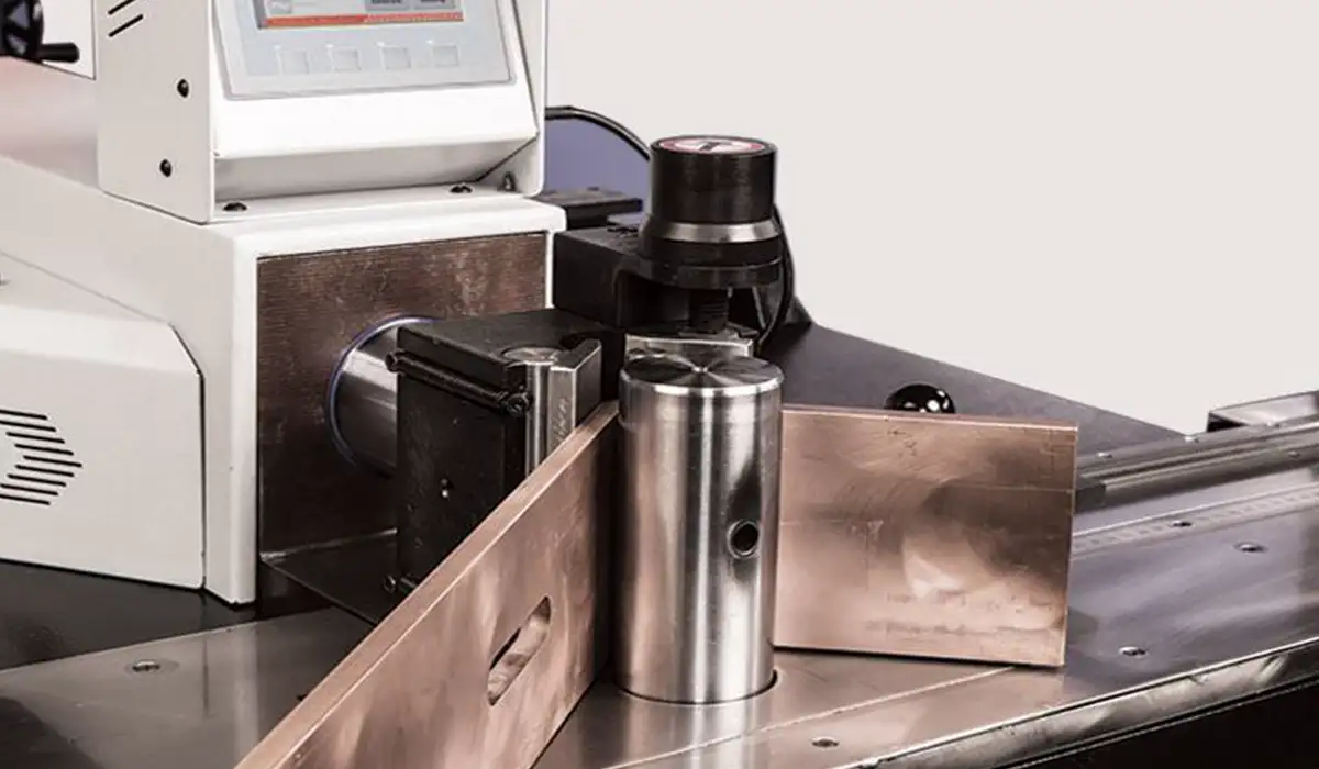
Copper busbar cold bending is the standard fabrication route in panel shops and on many installation sites. It avoids scale, preserves finish, and is fast when material temper and radius are compatible.
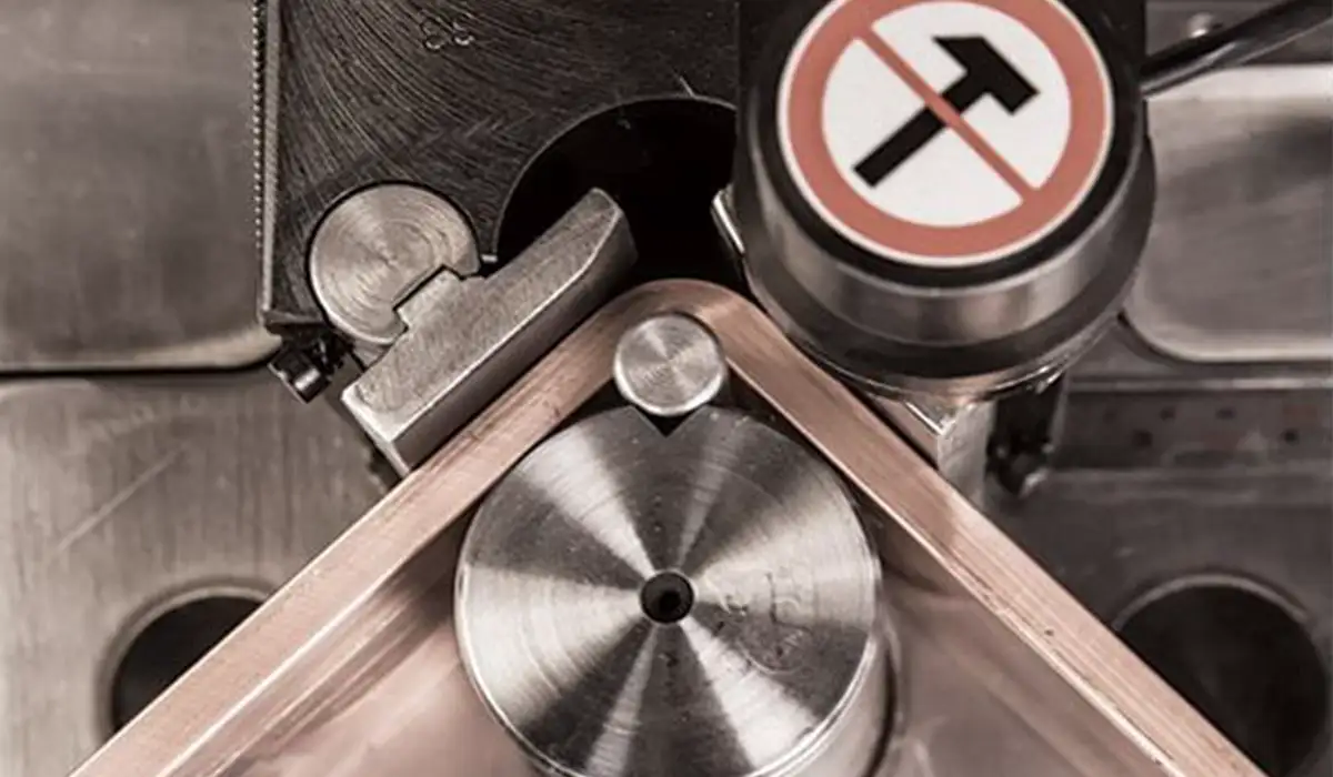
Press bending with matched punch-and-die tooling is the most common professional method. The die set directly controls inside radius, repeatability, and bend angle calculation consistency.
Three-point bending works for simpler shapes and smaller sections. The support span and punch travel influence the resulting radius, so it is useful but less precise than dedicated busbar forming dies.
Can you cold bend copper busbar on site? Yes, for suitable sizes and tempers — though a dedicated busbar machine in a workshop setting delivers far greater precision and repeatability than portable site tools. Very thick bars or hard tempers may exceed site-tool capacity.
For a comprehensive understanding of busbars in panels, we highly recommend reviewing this article.
Springback Allowance in Copper Busbar Bending
Springback is the elastic recovery that occurs after forming load is removed. In annealed copper it is lower than in many harder materials, but it is still enough to miss angle targets if ignored.
For many flat-wise bends, slight over-bending is enough; edge-wise bends, harder tempers, and larger radii usually need trial-based compensation or machine-controlled correction. Modern CNC systems even include spring-back compensation functions.
For Calculating Bend Allowance and Developed Length formulas checkout this page.
Hot Bending and Annealing of Copper Busbars
Do you need to anneal copper busbar before bending? Usually only when temper is hard, the required radius is tighter than cold bending permits, or the bar is thick enough to overload available tooling.
Published C11000 data shows excellent cold-work and hot-forming suitability, with annealing temperatures broadly listed around 700–1200°F. In workshop terms, controlled heating in roughly the 400–600°C range is commonly discussed for restoring ductility.
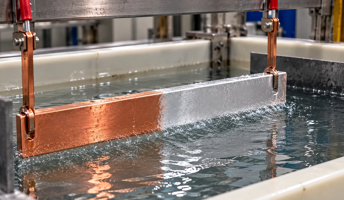
Annealing softens the copper, lowers yield strength, and improves bendability. Electrical conductivity remains essentially unchanged for ETP copper when the operation is controlled and the surface is cleaned before jointing.
Further exploration of flexible busbar types can be found in the following recommended reading.
Avoid overheating. Excessive temperature promotes oxidation and scale, which is especially unwelcome on contact surfaces that later need low-resistance bolted joints.
Read Electrolytic Tough Pitch for more detail.
Common Busbar Bending Defects and How to Avoid Them
The most useful answer to busbar bending defects and how to avoid them is to link each visible defect to one controllable cause. Most failures trace back to radius, support, alignment, die condition, or wrong temper assumptions.
Outer surface cracking is the most serious defect because it indicates the outer fibers exceeded available ductility. It is usually caused by undersized radius, hard temper, or edge-wise bending without proper support.
Inner-face buckling and cross-section distortion are typically tooling problems, not copper-quality problems. They appear when the bar is unsupported, misaligned, or forced through the wrong die geometry.
Surface scoring, twist, and wrong developed length are preventable shop errors. Clean dies, straight feeding, and measured bend allowance eliminate a surprising amount of scrap.
This article serves as a valuable resource for those seeking detailed information on busbar clearances.
| Defect | Cause | Prevention |
|---|---|---|
| Outer surface cracking | Bend radius too small for temper or width | Use correct minimum radius; anneal if needed |
| Inner face buckling | Edge-wise bend without die support | Use guided edge-bending die |
| Cross-section distortion | Excessive force, unsupported bar | Use matched punch and die; support bar length |
| Springback over-correction | Over-bending without measurement | Measure springback empirically and set die angle |
| Surface scratching / scoring | Die surface damage or contamination | Inspect and clean dies; use protective film |
| Twist along bar length | Uneven force application | Ensure bar is fully supported and aligned in die |
| Incorrect developed length | Bend allowance not calculated | Calculate blank length including bend allowance |
Workshop defect-prevention summary synthesized from copper forming and tooling guidance.
Busbar Bending Machines and Tooling Selection
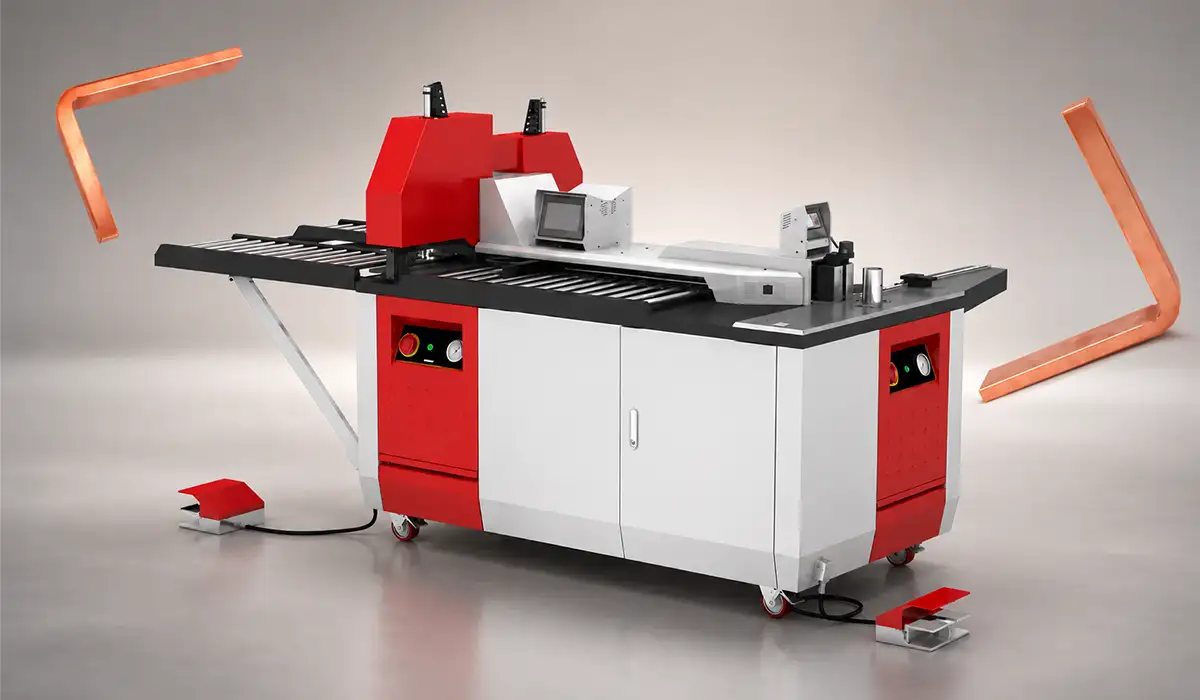
What machines are used for bending copper busbars? The practical choices are manual lever benders, hydraulic combination machines, and CNC busbar bending systems. The right answer depends on section size, tolerance demand, and production volume.
Manual tools suit small sections and occasional site work. They are affordable, but radius control and repeatability are limited, especially for edge-wise bends or busbar U-bend fabrication.
Hydraulic or electric combination machines are the panel-builder standard. They cut, punch, and bend with interchangeable busbar bending tool dies, making them ideal for routine copper strip bending and copper flat bar forming.
When evaluating a busbar fabrication machine for daily panel work, focus on bending capacity, die changeover speed, and whether the system supports both flat-wise and edge-wise operations.
CNC systems are best for batch production, consistent springback compensation, and complex sequences such as offsets, U-bends, and repeated right-angle bends. They cost more but reduce variation and setup waste.
| Machine type | Typical capacity | Accuracy | Cost level | Best use case |
|---|---|---|---|---|
| Manual lever bender | Small sections, low force work | Low to moderate | Low | Service work, simple site bends |
| Hydraulic / electric combo machine | Up to about 120–160 × 12 mm depending on machine | Good | Medium | Panel shops, daily fabrication |
| CNC busbar bender | Production-scale, complex sequences | High | High | Repetitive manufacturing, tight tolerances |
Conclusion about how Bending Copper Busbar
Successful copper busbar bending comes down to treating radius, temper, orientation, and tooling as a single decision rather than separate variables. Get any one of them wrong — an undersized radius on hard-drawn stock, an edge-wise bend in a flat-wise die, an uncompensated springback angle, or a blank cut without proper bend allowance — and the result is scrap, rework, or worse, a conductor with hidden residual stress that will fail under thermal cycling and fault loads. The good news is that none of this requires guesswork. Confirm the temper before you cut, plan flat-wise bends around the 1× thickness rule and edge-wise bends around the 1.5–2× width rule, match the die and support to the bar section, calculate developed length with a realistic K-factor, and validate with trial bends before committing a production run. Anneal when the geometry demands it, invest in guided tooling for edge-wise work, and let CNC compensation handle repeatability when volumes justify it. Done methodically, copper busbar bending is a controlled, predictable process that protects both the conductor’s electrical performance and its mechanical service life — which is exactly what the downstream assembly is counting on.
Further exploration of busbar system trends can be found in the following recommended reading.



Rate this article
Choose a rating from 1 to 5 stars.
No ratings yet