


The Role of Busbars in LV Switchgear Panels
A busbar system carries the full assembly current at a controlled temperature rise — IEC 61439-1 caps bare copper at 105 K and external-conductor terminals at 70 K — by giving every circuit one low-impedance shared path instead of point-to-point wiring.
That single shared path is what makes LV switchgear busbars so consequential. Because they feed everything downstream, a weakness in the bar affects the whole board, not one circuit. The role splits into three jobs, examined below: distributing power, connecting functional units, and enabling clean isolation and fault clearance.
Understanding busbars in the context of broader power infrastructure is essential for engineers and designers. For a complete overview of how busbars are applied across different systems and facilities, the following resource provides comprehensive guidance on electrical busbars.
Download this file to keep the key data, tables, and recommendations in one place.
Function of Busbars in LV Switchgear
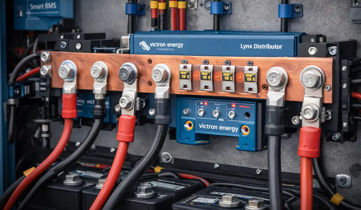
A busbar collects incoming power and distributes it across the panel on one low-resistance conductor; design it for a temperature rise of about 30 K and the distribution losses stay low while the bars run cool.
In practice, busbars do three things at once. They carry incoming current from the supply to the main distribution zone. They connect functional units — incomers, bus-couplers, and outgoing feeders — without dozens of separate cable runs. And they create defined points for isolation, so a fault can be cleared and a section worked on safely. On projects, a clean bar system also cuts assembly time and connection count, which reduces the number of joints that can later loosen or overheat.
The function of a busbar is closely related to how electrical panels are structured and organized. Gaining a deeper understanding of panel types and their internal layouts can help clarify the role busbars play in real-world applications. For further reading, this article on distribution board types is highly recommended.
For additional technical context, refer to this page.
Types of Busbars in LV Switchgear
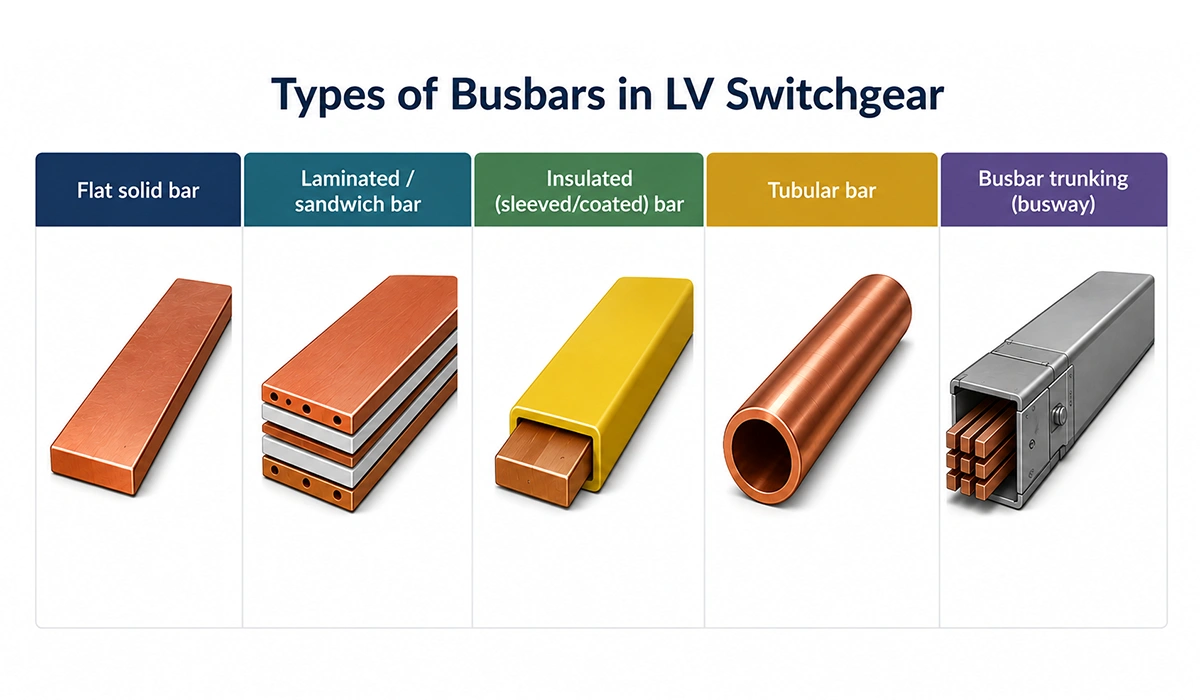
Match the busbar type to the duty: flat solid bar covers most LV panels up to a few thousand amperes, laminated and insulated bars cut inductance and footprint, and busbar trucking carries power along a run — each trading cost, space, and serviceability differently.
The choice is rarely about conductivity alone; it is about footprint, fault behavior, and how easily the bar is inspected and modified later. The table compares the common options.
| Type | Typical range | Strengths | Watch-outs / best fit |
|---|---|---|---|
| Flat solid bar | Up to a few thousand A | Simple, low cost, easy to fabricate and joint | Bulkier; higher inductance at high current |
| Laminated / sandwich bar | High current, compact builds | Low inductance, even current sharing, space-saving | Higher cost; harder to modify in the field |
| Insulated (sleeved/coated) bar | Any rating | Smaller clearances, touch-safe, dust-tolerant | Surface prep is critical; harder to inspect |
| Tubular bar | Very high current | Good strength-to-weight, lower skin effect | More complex jointing; needs space |
| Busbar trunking (busway) | Distribution along a route | Flexible tap-offs, fast install, reconfigurable | Joint quality along the run; higher cost |
Each busbar type has distinct characteristics that influence selection decisions for LV panels. Reviewing a structured comparison of busbar arrangements can help engineers choose the most suitable configuration for their specific panel design. This guide on busbar arrangements provides a useful reference.
Design Considerations for Busbars in LV Switchgear
Two duties size every LV busbar: continuous current within the temperature-rise limits, and short-circuit withstand against the peak fault force. Verify both, because the larger requirement governs.
Many in-service failures trace to designing for the first duty and forgetting the second. The three sections below take sizing, fault withstand, and material in turn.
Proper design of busbars requires referencing established guidelines and selection criteria specific to LV panel applications. Engineers working on panel design will benefit from consulting a dedicated resource on busbar selection to avoid common design oversights.
Sizing Busbars for LV Switchgear
Size the busbar for current-carrying capacity by holding temperature rise inside the IEC 61439-1 limits — 105 K for bare copper, 70 K at terminals — using current density near 1.0–1.6 A/mm² in enclosed panels and derating for ambient, grouping, and the rated diversity factor.
The controlling variable is temperature rise (ΔT), the difference between conductor and ambient temperature, not the absolute reading. Busbar sizing for LV switchgear therefore starts from the allowable ΔT and works back to a cross-section. Then it applies the rated diversity factor (RDF, typically 0.8–1.0), which recognizes that not every outgoing circuit runs at full load at once. Enclosure ventilation, an ambient of 35–40 °C, altitude, and bar grouping all reduce real-world busbar current carrying capacity. Shop-floor reality is that buying to nameplate amperes without derating for the enclosure is the most common sizing error we see — the bar that passes on the bench overheats in a sealed panel.
Accurate busbar sizing directly impacts panel safety and energy efficiency. Using the right methodology and tools is critical to achieving reliable results. For a practical approach to calculating busbar dimensions, this article on busbar sizing offers step-by-step guidance.
Short-Circuit Withstand and Mechanical Strength
Design the bar and its supports for the peak fault, not just the rms current — the force between parallel bars rises with the square of peak current (per IEC 60865-1), and verification is mandatory unless Icw is ≤ 10 kA or a current-limiting device caps let-through current at ≤ 17 kA.
Two ratings describe the fault duty. The short-time withstand current (Icw) is the rms current the bar carries for a defined time, usually one second, while the peak withstand current (Ipk) is the instantaneous crest the bars must survive mechanically. Because the electrodynamic force on busbars scales with Ipk², a modest rise in fault level produces a large rise in force. Two outcomes follow: the bar must resist the thermal I²t energy without annealing, and the supports must resist the mechanical force without deflecting into adjacent phases. Busbar short-circuit testing, or calculation to IEC 60865-1, confirms both. A current-limiting circuit breaker that cuts off the peak can reduce the force several-fold, which is often cheaper than a heavier bar.
Short-circuit withstand is one of the most critical performance parameters for busbars in LV switchgear. A detailed technical breakdown of calculation methods and mechanical considerations can be found in this dedicated article on short-circuit withstand.
For a more detailed breakdown, download the complete guide here.
Material Selection for Busbars
Choose copper for compact, high-duty LV busbars and aluminium where weight or cost dominates — aluminium needs roughly 1.6× the cross-section of copper for the same current, plus bimetallic hardware to prevent galvanic corrosion at joints.
Material choice is a balance of conductivity, strength, corrosion behavior, and cost. The matrix sets out the busbar material for LV switchgear options and when each win.
| Criterion | Copper (Cu-ETP) | Aluminium (EN AW-1350) | Tinned copper |
|---|---|---|---|
| Conductivity | Highest (~58 MS/m, ~101% IACS) | ~61% IACS → ~1.6× section needed | As copper |
| Section for same current | Smallest | ~1.6× larger | As copper |
| Weight / material cost | Heavier, costlier | Lighter, cheaper | Slightly above bare copper |
| Corrosion / oxidation | Good; oxide stays conductive enough | Oxide is insulating — needs careful prep | Best surface protection |
| Jointing | Simple, standard hardware | Needs bimetallic hardware + anti-oxidant | Simple; suits humid conditions |
| Best fit | Compact or high-duty panels | Weight- or cost-driven, larger enclosures | Marine, humid, high-pollution sites |
Selection rule: default to copper for compact or high-duty LV panels; choose aluminium when the enclosure can accept the larger section and weight or budget dominates; specify tinned copper for humid, marine, or high-pollution environments. Always state the grade and temper in the purchase order, never leaving it open.
Material selection for busbars is a foundational decision that affects both performance and long-term reliability. For engineers comparing flexible conductor options in space-constrained applications, this article on flexible busbar types provides a valuable perspective.
Installation and Configuration of Busbars in LV Switchgear
Installation decides whether the design survives reality: correct support spacing, phase arrangement, and clearances turn a paper rating into a panel that holds both its temperature rise and its fault withstand on site.
A bar sized perfectly on paper still fails if the supports are too far apart, the phases are crowded, or the spacings are short. The three sections below cover supports, configuration, and spacing.
Installation quality is directly linked to compliance with clearance and creepage requirements. Understanding these spatial constraints early in the design process helps avoid costly rework on site. This resource on busbar clearances covers the key requirements in detail.
Busbar Support Systems
Space busbar supports so they carry the peak short-circuit force without resonance or permanent deflection — the force scales with peak current squared and inversely with support spacing, so closer supports cut the load each insulator sees.
Supports and bracing hold the bars in position and transfer the fault force into the structure. Two failure modes matter. The first is overstress, where a single insulator sees more force than it can take and cracks. The second is resonance, where the bar’s natural frequency sits near the network frequency or its harmonics and the bar flexes into fatigue. In the field, supports — not the bars — are often the weak link, because builders copy a support pitch from a lower-fault job. Re-check the pitch whenever the fault level rises, and torque every mounting to specification.
Busbar support systems must be evaluated alongside the overall panel busbar design to ensure mechanical integrity under fault conditions. A broader perspective on how busbars integrate into LV panel systems is available in this article on LV panel busbars.
Busbar Configuration
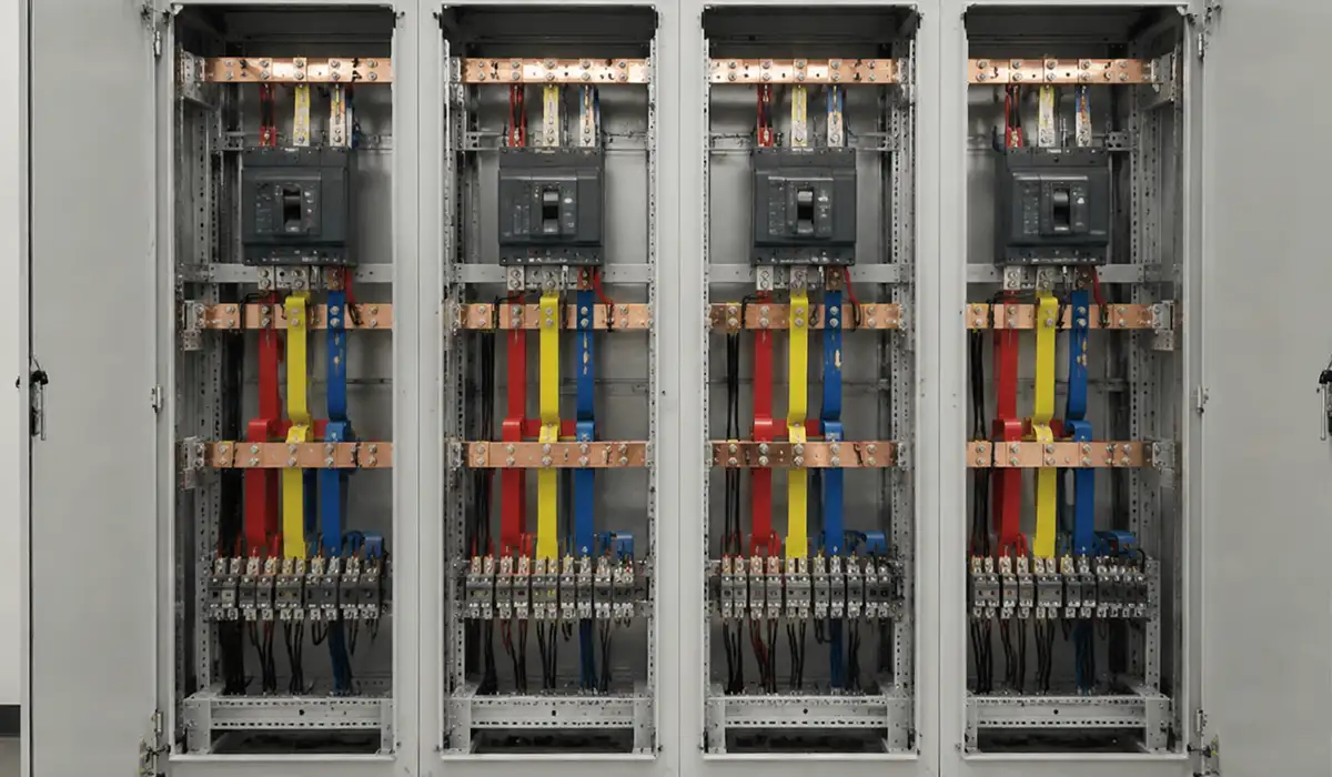
Arrange the phases and neutral for balanced current sharing and low loss — a tidy three-phase layout with a correctly sized neutral handles non-linear loads, where harmonic currents can push neutral current toward, or beyond, phase current.
Busbar configuration in switchgear ranges from single-phase feeders to three- and four-pole main bars with a neutral and protective bar. Spacing, phase order, and parallel-bar sharing all affect loss and temperature rise. The classic procurement error is an undersized neutral: on loads with switch-mode supplies or LED drivers, triplen harmonics add in the neutral and can drive it to phase-current levels or higher. Where such loads dominate, size the neutral equal to — or larger than — the phases, and keep the layout symmetrical so the phases share current evenly.
Busbar configuration choices — particularly between single and double busbar schemes — have long-term implications for switchgear reliability and maintenance flexibility. A technical comparison of these schemes is available in this article on busbar schemes.
Compliance with Standards and Regulations for Busbars in LV Switchgear
Compliance is verification, not paperwork: IEC 61439 and UL 508A both require documented proof — temperature-rise, short-circuit, and dielectric verification — that the busbars in LV switchgear panels meet their stated ratings.
The two frameworks pursue the same goal through different routes. The sections below separate the technical standards from the regional rules that wrap around them.
Understanding which standards govern busbar design and testing is essential for any LV panel project. For a comprehensive review of the applicable international and regional requirements, this article on busbar standards is an important reference.
IEC 61439 and UL 508A Standards
Meet IEC 61439’s verified ratings in IEC markets and UL 508A’s marked SCCR in North America — and remember that under UL 508A the panel’s short-circuit current rating equals its lowest-rated power component.
IEC 61439 replaced the old type-tested versus partially-type-tested split with three equivalent verification routes: testing, calculation, and comparison with a tested reference design. It verifies temperature rise (with the RDF), short-circuit withstand, and dielectric strength, and IEC 61439 busbar requirements flow from those checks. UL 508A takes a different path: Supplement SB builds the panel’s SCCR from the weakest power-circuit component, and the rating must be marked on the nameplate. The contrast matters at procurement — an IEC Icw rating and a UL SCCR are not interchangeable, and exporting between regions usually means a second verification.
Applying IEC 61439 and UL 508A correctly requires a solid understanding of how busbar ratings are established and verified. For engineers who want to go deeper into the fundamentals, this introductory article on what is busbar provides a strong foundation.
You can review the original source here to verify the technical details.
Regulatory Considerations
Adopt the regional flavor of the standard — EN IEC 61439 with national deviations across Europe, UL 508A and NEC Article 409 in North America — and make sure the assembly’s Icw or SCCR equals or exceeds the site’s prospective fault current.
Beyond the base standards, local codes decide what an inspector or insurer will accept. In Europe, the LV Directive and harmonized EN IEC 61439 parts apply, with national deviations layered on top. In North America, NEC Article 409 requires an SCCR marking on industrial control panels, and the installation must keep the available fault current at or below that mark. The practical takeaway for EPCs and consultants is simple: pin down the site’s prospective short-circuit current early, because every busbar, support, and protective device is then sized against it.
Regulatory compliance for LV switchgear busbars also intersects with power factor management and overall system efficiency requirements. For a practical overview of how power factor affects panel design decisions, this article on power factor is recommended reading.
Maintenance and Troubleshooting of Busbars in LV Switchgear
Catch busbar problems before they trip the panel: NFPA 70B (2023) now requires infrared thermography of electrical equipment at least every 12 months, and a rising joint temperature difference is the earliest reliable warning.
Maintenance of busbars in switchgear is condition-based, not calendar-only. Because the joints carry the same current as the bar but add contact resistance, they are where heat and degradation concentrate. The two sections below cover how to inspect and what typically goes wrong.
Effective maintenance of busbars in LV switchgear starts with understanding the components that make up the busbar connection system. Terminal busbars are particularly important in this context, and this article on terminal bus bar offers useful technical detail for maintenance engineers.
This website offers useful supporting information for understanding the subject more clearly.
Inspection Guidelines
Run a three-layer inspection — visual, infrared thermography under load, and electrical tests — comparing each joint’s temperature rise against similar joints and ambient, with thermography performed at least annually per NFPA 70B.
Start with a visual check for discoloration, looseness, and signs of arcing. Then scan under a representative load with an infrared camera, because a cold panel hides every joint problem. NFPA 70B works on Delta-T: compare similar joints under similar load, and flag the outliers. Finish with electrical tests — contact resistance at each joint with a micro-ohmmeter, and insulation resistance across the bar system. Trend the readings over time. A single snapshot tells you less than a joint that has crept up 10 K since the last visit.
Inspection routines for busbars are most effective when supported by reliable design software that tracks parameters over time. For engineers looking to integrate digital tools into their busbar management workflow, this article on busbar design software provides a practical overview.
Common Maintenance Issues in LV busbar
Most LV busbar faults come back to the joints: oxidation, under-torque, overload, and corrosion drive contact resistance and temperature up — so fix the root cause by cleaning, re-torquing, and re-rating rather than resetting and re-energizing.
The failure loop is self-reinforcing: higher resistance makes more heat, more heat accelerates oxidation and loosening, and resistance climbs again until the joint burns out. The table links each symptom to its cause, the consequence of ignoring it, and the corrective action.
| Symptom | Likely cause | Consequence if ignored | Corrective action |
|---|---|---|---|
| Hotspot at a joint (on IR) | Oxidation or under-torque | Runaway resistance, eventual burnout | Clean faces, re-torque to spec, re-scan ΔT |
| General overheating | Undersized section, overload, poor ventilation | Insulation ageing, capacity loss | Re-rate the load, improve cooling, resize the bar |
| Discoloration or odor | Sustained overtemperature | Dielectric breakdown, fire risk | Investigate load and joints; replace degraded parts |
| Corrosion or oxidation | Humidity, dissimilar metals | Rising resistance, mechanical weakening | Use tinned bars and bimetallic hardware; reseal |
| Loose support or vibration | Inadequate bracing, prior fault | Fatigue, deflection, raised fault risk | Re-torque, add supports, recheck spacing |
Common maintenance issues in LV busbars are often linked to how the busbar trunking system is integrated into the panel. Understanding the characteristics and vulnerabilities of trunking systems can help teams prevent recurring faults. This article on busbar trunking is a recommended resource.
Conclusion (Busbars in LV Switchgear Panels)
Busbars decide how much current an LV panel can carry, how well it survives a fault, and how safely it ages. Treat them as a two-duty problem — continuous current within the IEC 61439-1 temperature-rise limits, and short-circuit withstand against the peak electrodynamic force — and most failures never start. From there, the decisions are clear: choose the material for the duty, brace the bars for the fault, set clearances by Uimp and creepage by pollution degree, and verify by test, calculation, or design rules. Then keep the system healthy with annual infrared thermography and routine joint checks. For final sizing and ratings, always confirm against manufacturer data and the current editions of IEC 61439 and UL 508A.
Since busbars play a crucial role in the production of electrical panels, obtaining more information about busbar in panels can be very important and essential for anyone involved in LV switchgear design and maintenance.