


What is bus bar in electrical? Materials, Types, Uses, and Advantages
Before going deeper into busbar design, sizing, and applications, the table below gives a quick overview of the most important busbar characteristics. It summarizes the common materials, physical shapes, typical uses, and main advantages of electrical busbars in power distribution systems.
| Busbar Characteristic | Common Options | Typical Use | Main Advantage |
|---|---|---|---|
| Material | Copper or aluminum | Electrical panels, switchgear, substations, and power distribution systems | High conductivity, mechanical strength, and reliable current flow |
| Shape | Flat bar, rectangular bar, round bar, laminated busbar, or flexible busbar | Compact current distribution inside electrical assemblies | Space-saving layout and easier connection between electrical components |
| Use | Main busbar, distribution busbar, neutral busbar, ground busbar, or DC busbar | Connecting incoming power, circuit breakers, feeders, transformers, and loads | Cleaner wiring, lower resistance, and more organized power distribution |
| Advantage | Compact design, high current capacity, easier inspection, and better heat management | Low-voltage and medium-voltage switchgear, battery systems, EV systems, and industrial panels | Improved reliability, easier maintenance, and professional panel layout |
Despite ongoing design developments over the past few decades in the power, motor, industrial, and automotive industries, busbars remain pivotal to power distribution and vital for industries ranging from manufacturing to renewable energy. Their usage underpins the efficiency and reliability of electrical systems globally. In 2022, the busbar market was valued at just over USD 15 billion, with projections suggesting growth to almost USD 24 billion by 2030 — a clear indicator that this component, despite its simplicity in concept, is becoming increasingly critical in modern power infrastructure.
Further exploration of Electrical Busbars & Power Distribution Systems can be found in the following recommended reading.
If you’d rather listen than read, feel free to play the audio file below for the rest of this article.
How does busbar work?
Because the conductor’s resistance is extremely low, all tap-off points see approximately the same voltage — the fundamental advantage of a power bus over distributed cable runs. In three-phase systems, three phase busbars (L1, L2, L3) plus a neutral bar operate in parallel planes with defined phase-to-phase clearance maintained throughout.
If the information related to busbar efficiency was interesting and informative, researching power factor can be very engaging.
The busbar system incorporates isolators and circuit breakers. In the event of a fault, the circuit breaker trips off, allowing the faulty section of the busbar to be swiftly disconnected from the circuit. This mechanism ensures that disruptions are localized, prevents faults from spreading throughout the system, and maintains the integrity and reliability of the power distribution network.
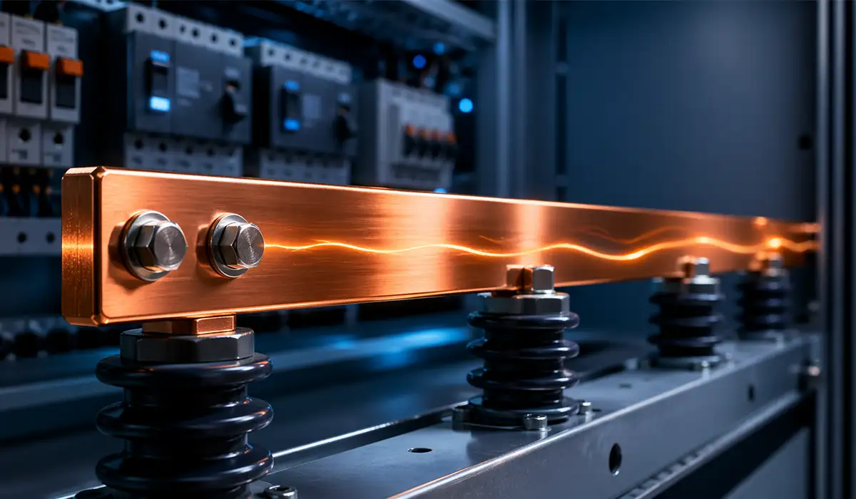
As load current increases, I²R heating rises with the square of current. IEC 61439-1 limits the temperature rise of bare copper connections to 70 K above a 40°C ambient (max 110°C), making cross-section and surface finish the primary thermal design variables for any current rail.
When the current rating is exceeded, resistive heating escalates, voltage drop increases, and insulation failure can follow — an irreversible consequence of under sizing the distribution bar. This is why ampacity verification is non-negotiable before final busbar specification.
What is a busbar used for?
A busbar in electrical systems is a solid metallic conductor used to carry and distribute electric current inside switchgear, distribution boards, substations, control panels, battery systems, and industrial power equipment. In most applications, an electrical busbar is made from copper or aluminum because these materials provide high conductivity, mechanical strength, and reliable current flow.
The main purpose of a busbar is to create a common power distribution point. Instead of routing several large cables through an electrical panel, engineers can use a busbar system to connect incoming power to circuit breakers, feeders, protective devices, and outgoing loads in a cleaner and more compact arrangement.
The performance and reliability of a busbar system are closely related to manufacturing precision. To achieve accurate cutting, punching, and bending processes, many manufacturers use a Busbar fabrication machine. This equipment helps produce high-quality busbars with consistent dimensions, improving efficiency in the production of electrical panels, switchgear, and power distribution systems.
Common uses of busbars include:
- Distributing power inside electrical panels: Busbars transfer current from the main incoming supply to multiple outgoing circuits.
- Connecting switchgear components: They link circuit breakers, disconnectors, contactors, fuses, and protection devices.
- Supporting high-current applications: Busbars are suitable for systems where cables may become bulky, difficult to manage, or less efficient.
- Improving panel organization: A busbar system helps reduce wiring complexity and creates a cleaner internal layout.
- Reducing electrical resistance: Properly designed copper or aluminum busbars can help reduce power loss and heat generation.
- Improving maintenance access: Busbars make electrical connections easier to inspect, tighten, test, and service.
- Providing mechanical stability: Compared with flexible cables, busbars offer a more rigid and stable connection path.
For this reason, busbars are widely used in low-voltage and medium-voltage switchgear, power distribution panels, transformer connections, battery packs, EV systems, renewable energy equipment, and industrial automation cabinets. In professional panel building, the performance of a busbar depends not only on its material and size, but also on accurate cutting, punching, bending, spacing, surface quality, and joint preparation.
A Busbar Bending Machine plays an important role in producing accurate copper and aluminum busbars for electrical panels, switchgear, substations, EV systems, and power distribution assemblies. Since busbars must carry high current while maintaining proper spacing, clean connections, and reliable thermal performance, precise bending helps ensure the conductor fits correctly inside compact electrical layouts without reducing mechanical strength or joint quality. By using a dedicated busbar bending machine, manufacturers can improve fabrication accuracy, reduce wiring complexity, and produce safer, more efficient busbar systems for modern power distribution.
Busbar Materials: Copper vs. Aluminum — Properties, Trade-offs, and Selection Criteria
Material selection is the first specification decision for any busbar installation. Electrolytic tough pitch copper (ETP, C110) achieves ~58 MS/m conductivity; aluminum alloy 6101-T6 reaches ~34 MS/m — meaning aluminum requires approximately 1.6× the cross-section for equivalent current capacity. Copper busbar current carrying capacity per mm² is approximately 1.2–1.6 A/mm² (bare, naturally ventilated); aluminum achieves 0.8–1.0 A/mm². Procurement is governed by ASTM B187 for copper and ASTM B317 for aluminum 6101.
Weight and cost significantly shift the decision. Aluminum is approximately 70% lighter by volume than copper; for equivalent ampacity, an aluminum busbar weighs approximately 50% less — a decisive advantage in vertically mounted bus bar trunking systems. However, aluminum’s thermal expansion coefficient (23 µm/m·K) exceeds copper’s (17 µm/m·K), requiring expansion joints on long runs.
Bimetallic connections between copper and aluminum demand anti-oxidant compound and bimetallic washers to prevent galvanic corrosion, per IEEE 837 and AS/NZS 3008. For large-capacity distribution systems, aluminum delivers a compelling total installed cost advantage despite lower conductivity. The difference between busbar and cable in power distribution is most apparent here: a busbar’s rigid cross-section allows precise ampacity calculation without derating factors applied to bundled cables.
For a comprehensive understanding of Copper vs Aluminum Busbar, we highly recommend reviewing this article.
Copper busbar Grade Selection: Not All Copper Is the Same
When specifying copper busbars, the grade matters more than many engineers realize. Electrolytic Tough Pitch Copper (ETP, C110) — at least 99.90% purity — is the standard choice for power distribution switchgear and high-demand electrical installations, offering the best balance of conductivity and cost. Oxygen-Free High Conductivity (OFHC) Copper reaches up to 99.95% purity and is reserved for high-vacuum environments, cryogenic devices, and precision research applications where even trace oxygen content is problematic. Silver-Bearing Copper (0.03–0.12% silver) enhances mechanical strength and wear resistance at elevated temperatures — the specification of choice for high-cycling contact applications and resistance welding electrodes. Understanding these grades prevents over-specification in standard panel applications and under-specification in demanding industrial environments.
Table 1 — Copper vs. Aluminum Busbar: Key Differences
| Property | Copper Busbar | Aluminum Busbar |
|---|---|---|
| Electrical Conductivity | ~58 MS/m (100% baseline) | ~37 MS/m (~60% of copper) |
| Current Capacity (Ampacity) | High ampacity for a given size; 1.2–1.6 A/mm² | Needs ~1.6x the cross-section for equivalent ampacity; 0.8–1.0 A/mm² |
| Density / Weight | ~8.9 g/cm³ — heavy | ~2.7 g/cm³ — ~70% lighter by volume than copper |
| Mechanical Strength | High tensile strength and rigidity | Softer; lower tensile strength depending on alloy |
| Corrosion Resistance | Good; forms stable conductive copper oxide; tin or silver plating enhances performance | Forms insulating oxide film; requires antioxidant compound and Al-rated connectors |
| Thermal Expansion | 17 µm/m·K — moderate | 23 µm/m·K — higher; expansion joints required on long runs |
| Cost | Higher cost; price-volatile (3–4x aluminum by weight) | Significantly cheaper; relatively stable pricing |
| Fabrication | Easy to solder and plate; heavier to cut/punch | Requires specialized welding; easier to cut and drill |
| Recyclability | ~65% of in-use copper is recycled | ~75% of in-use aluminum is recycled; highly eco-friendly |
Busbar Types by Physical Form Factor
Busbars are not a single product — they come in several distinct physical forms, each suited to different electrical and mechanical demands.
Flat Strip Busbars
The most prevalent form is the flat, rectangular cross-section bar. Flat copper busbars are widely used in panels and switchgear because their broad surface area dissipates heat well and provides ample contact surface for bolted connections. The flat geometry also makes phase-to-phase spacing predictable and easy to verify against creepage requirements per IEC 60664-
Solid Rod and Round Busbars
These have a circular cross-section, either solid or hollow. Their lower surface area relative to volume makes them less thermally efficient than flat bars for the same current — they run hotter for equivalent ampacity. Round busbars find use primarily in outdoor high-voltage substations where their profile sheds rain and ice more effectively than flat bars.
Hollow Tubular Busbars
A tubular busbar is essentially a conductive pipe — rectangular or circular. The hollow center reduces material weight while allowing heat to dissipate from both inner and outer surfaces. For very large current ratings (above 4,000 A) in confined spaces, tubular designs often represent the most practical solution, balancing ampacity against structural load on support insulators.
Laminated and Flexible Busbars
Flexible busbars are built from multiple thin copper foil layers, stacked and bonded with dielectric films under heat and pressure. This laminated structure simultaneously addresses two problems: it eliminates the skin effect penalty by keeping each layer thinner than skin depth, and it provides mechanical compliance to absorb vibration and thermal movement. These designs are the standard interconnect for EV battery modules, UPS internal wiring, and high-frequency power converters where both low inductance and vibration resistance are mandatory. Insulation requirements for laminated flexible busbars are governed by IEC 62497.
For a comprehensive understanding of flexible busbar types, sizing, and standards, we highly recommend reviewing this article.
Custom Profile Busbars
Modern stamping and CNC machining allow busbars to be manufactured in complex bent or multi-layer profiles to fit inside compact enclosures. Progressive die stamping is common for high-volume production runs; laser cutting and CNC machining serve prototypes and small batches. Engineers should verify that all bend radii maintain the minimum conductor cross-section and that hole locations preserve adequate edge distances at all connection points.
Table 2 — Busbar Types: Material, Application and Governing Standard
| Busbar Type | Material / Form | Key Application | Relevant Standard |
|---|---|---|---|
| Single Busbar | Copper / Aluminum flat bar | Small substations, distribution boards | IEC 61439-1 |
| Sectionalized Busbar | Copper bar with isolators | Medium substations, selective fault clearing | IEC 61439-2 |
| Double Busbar | Dual copper bars + coupler CB | Large HV substations, no interruption needed | IEC 62271-200 |
| Ring Busbar | Copper, loop topology | Transmission networks, high availability | IEEE C37.20.1 |
| Busbar Trunking (BTS) | Copper/Al in metal duct | High-rise buildings, industrial risers | IEC 61439-6 |
| Isolated Phase Bus | Each phase in separate enclosure | Generators, transformer connections | IEEE C37.23 |
| Laminated Flexible | Multi-layer copper foil | EV batteries, power electronics, UPS | IEC 62497 |
Busbar Configurations: Single Bus, Double Bus, Ring Bus, and Beyond
Busbar switching arrangements directly determine substation reliability, maintenance access, and fault tolerance. The single busbar is the simplest and lowest-cost scheme: one conductor connects all feeders, but a fault causes total loss of supply — acceptable only for non-critical small substations. Every circuit is tied to that one bus; if maintenance is required or a fault occurs, the system must be fully de-energized.
Adding a bus-section circuit breaker creates the sectionalized busbar: a fault on one section can be isolated without losing the entire substation — a meaningful reliability improvement at minimal incremental cost. The double busbar introduces a second bus and a coupler circuit breaker; any feeder can be transferred between buses during maintenance without interruption, making it the de-facto standard in medium and large substations. A double busbar system is distinguished by this feeder transfer capability, which eliminates supply interruptions during maintenance. Under normal conditions, loads run from the main bus; when that bus requires attention, circuits transfer to the reserve bus via switching operations.
The ring busbar forms a closed loop: any single circuit breaker can open for maintenance while supply continuity is maintained throughout, since power can reach any circuit from either direction around the ring. The breaker-and-a-half arrangement — three CBs shared across each feeder pair — provides the highest operational flexibility and is the standard configuration for EHV (extra high voltage) transmission substations where no interruption of any kind is acceptable.
Further exploration of what is a busbar in an electrical panel
can be found in the following recommended reading.
Busbar Trunking Systems (BTS): Prefabricated Distribution for High-Rise and Industrial Use
A bus bar trunking system (BTS) — also called a busway or bus duct — differs from a site-engineered busbar in one critical respect: it is a type-tested, factory-assembled product with plug-in tap-off units that allow branch connections without electrical shutdown. IEC 61439-6 governs BTS; North American installations follow UL 857.
Three principal variants serve distinct installation contexts. The feeder busway connects a transformer to a main distribution board with no intermediate tap-offs — optimized for low-loss, high-ampacity power transfer. The plug-in busway provides tap-off boxes at regular intervals, making it ideal for factory floors and data centers requiring reconfigurable power distribution without planned outages. Rising mains — vertical BTS installed in high-rise building risers — eliminate multiple large cable runs in congested shafts and supply floor-level distribution boards throughout the structure.
It is worth clarifying the distinction engineers sometimes blur: a busbar is the bare or insulated conductor strip itself, mounted on insulators inside switchgear or a panel. A bus duct (busway or BTS) is the complete metallic enclosure housing a group of busbars for power distribution over distance — a different product with modular standardized connectors, type-tested as an assembly, and designed to be reconfigured or extended without custom fabrication.
IP rating (typically IP54 for industrial environments) and fire performance requirements are verified as part of IEC 61439-6 type testing, ensuring the busbar trunking system performs reliably in demanding environments.
Correct busbar selection depends as much on sizing discipline as on material and configuration. An undersized busbar creates a thermal bottleneck; oversizing wastes cost and space. The following section provides the engineering framework from continuous current determination through short-circuit withstand calculation.
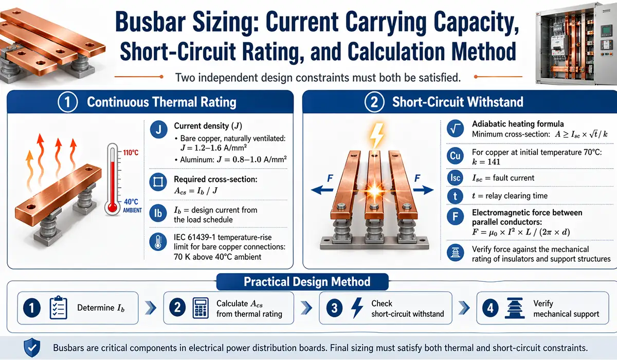
Busbar Sizing: Current Carrying Capacity, Short-Circuit Rating, and Calculation Method
Busbar sizing for industrial applications requires satisfying two independent design constraints. The first is continuous thermal rating: apply current density J = 1.2–1.6 A/mm² for bare copper (naturally ventilated) or J = 0.8–1.0 A/mm² for aluminum. Required cross-section: Acs = Ib / J, where Ib is the design current from the load schedule. IEC 61439-1 limits temperature rise of bare copper connections to 70 K above 40°C ambient.
The second constraint is short-circuit withstand. The adiabatic heating formula A ≥ Isc × √t / k (where k = 141 for copper at initial temperature 70°C) determines the minimum cross-section to survive fault current Isc for relay clearing time t. The electromagnetic force between parallel conductors during a fault — F = μ₀ × I² × L / (2π × d) — must also be verified against the mechanical rating of insulators and support structures.
For a comprehensive understanding of Busbar Sizing, we highly recommend reviewing this article.
Key Busbar Design Criteria for Electrical Panels and Switchgear
Busbar design is not only about choosing a copper or aluminum conductor. A reliable busbar system must be checked from electrical, thermal, mechanical, and manufacturing points of view. If one design factor is ignored, the problem may appear later as overheating, joint failure, insulation stress, or mechanical deformation during fault conditions.
- Current rating and temperature rise: The busbar must be sized according to load current, ambient temperature, duty cycle, and heat dissipation conditions.
- Material selection: Copper is preferred for compact, low-resistance layouts, while aluminum is often selected when weight and cost are more important.
- Short-circuit withstand: The busbar and its supports must resist thermal stress and electrodynamic forces during fault current conditions.
- Joint design: Contact surface quality, flatness, plating, bolt torque, and interface pressure directly affect contact resistance and hot-spot prevention.
- Insulation coordination: Clearance, creepage distance, insulation material, and pollution level must match the system voltage and operating environment.
- Mechanical support: Support spacing, bend radius, vibration, and thermal expansion must be considered before installation.
- Manufacturability: Hole position, edge quality, bending accuracy, and surface preparation must be compatible with the selected busbar fabrication process.
For panel builders, accurate busbar cutting, punching, and bending are part of the design quality. Poor fabrication can reduce joint reliability, increase assembly difficulty, and affect the long-term performance of the electrical panel.
📎 Attachment A (recommended): Worked example — ‘Sizing a 1,600A copper busbar for a 2,000 kVA transformer secondary in a 40°C ambient’ — showing all calculation steps, cross-section selection, and short-circuit verification. Ideal downloadable asset for engineering forums. (PDF)
Busbar Simulation: Predicting Performance Before Manufacturing
Before committing to a final busbar design, simulation has become a standard step in the engineering workflow — not a luxury reserved for large projects. Modern cloud-native finite element analysis (FEA) and computational fluid dynamics (CFD) tools allow engineers to model the electrical, thermal, and mechanical behavior of a busbar before a single piece of copper is cut, eliminating costly physical prototype iterations. If the insights you gained from busbar simulation were intriguing, exploring busbar design software might be of great interest to you as well.
Further exploration of SimScale can be found in the following recommended reading.
Key Parameters Evaluated in Busbar Simulation
Accurate simulation of busbars requires evaluating several interdependent parameters simultaneously — a challenge that traditional isolated analysis methods handle poorly.
Table 3 — Key Busbar Simulation Parameters
| Parameter | Purpose and Engineering Significance |
|---|---|
| Current Density | Ensures uniform current distribution across the cross-section; identifies hot spots and potential overload regions before manufacturing |
| Voltage Drop | Assesses efficiency and energy loss across the full length; critical for long BTS runs where voltage regulation at end-of-bus matters |
| Power Loss (I²R) | Calculates resistive heating under full load to evaluate thermal performance and predict junction temperatures at bolted connections |
| Temperature Rise | Critical for insulation material selection and thermal safety under continuous load; must remain within IEC 61439-1 limits (70 K above 40°C ambient) |
| Short-Circuit Forces | Predicts mechanical stress and deflection of the conductor and support insulators during fault conditions; validates support spacing |
| Eddy Current Losses | Quantifies energy losses from circulating currents induced by alternating magnetic fields; guides lamination thickness selection |
| Inductance and Capacitance | Important for power electronics and AC systems where transient voltage spikes and harmonic currents affect switching behavior |
| Electric Field Strength | Ensures dielectric clearances and insulation reliability in medium- and high-voltage systems; identifies field concentration at sharp edges |
| Modal Frequency | Identifies natural vibration modes to avoid resonance with mechanical forcing frequencies from nearby motors, transformers, or structural elements |
Common Busbar Suppliers and Electrical Component Brands
Busbars and related connection components are supplied by different types of companies, including electrical component manufacturers, terminal block brands, connector manufacturers, and industrial distribution suppliers. Depending on the application, buyers may need copper or aluminum busbars, busbar connectors, terminal block accessories, power distribution blocks, or custom-fabricated busbar parts for switchgear and electrical panels.
Examples of well-known companies active in busbar-related electrical components include:
- Phoenix Contact: supplies electrical connection components, terminal block systems, and busbar-related accessories for industrial control and power distribution applications.
- TE Connectivity: offers power busbar solutions and busbar connector products for high-current electrical connection applications..
- Weidmüller: provides terminal blocks, DIN rail connection systems, and busbar accessories used in industrial electrical panels.
For panel builders and switchgear manufacturers, selecting the right supplier depends on current rating, voltage level, conductor material, insulation requirements, terminal compatibility, installation space, and compliance with the applicable electrical standards.
How Busbars Are Made: From Raw Material to Finished Conductor
Understanding the manufacturing process helps engineers specify busbar dimensions and tolerances that are actually achievable — avoiding the common mistake of calling out features that are either impossible or prohibitively expensive to produce consistently.
Rigid busbars start as copper or aluminum strip or bar stock. The sequence is: cut to length, punch or drill connection holes, bend to the required profile, deburr all edges, apply plating or coating, add insulation sleeves if required, then perform dimensional and electrical inspection. For high-volume production, progressive die stamping produces consistent parts at the lowest unit cost. For prototypes and small batches, laser cutting or CNC machining provides the flexibility to iterate on geometry without tooling investment. Laminated busbars follow a different route: thin copper conductors are stacked with dielectric films between layers, then bonded under controlled heat and pressure — a process closer to printed circuit board fabrication than conventional metalworking.
For a comprehensive understanding of Busbar Prices , we highly recommend reviewing this article.
Hole location and edge quality matter more than many specifications acknowledge. Contact resistance at a bolted joint is directly affected by the flatness of the mating surfaces, the quality of edge breaks around holes, and the uniformity of plating at the contact face. Specifying tight tolerances on hole position is straightforward; ensuring that the plating process actually reaches inside recessed areas requires deliberate design of the plating geometry and explicit conversation with the fabricator during design review.
Busbar Jointing Methods: How Sections Are Connected
Busbars frequently arrive on site in sections that must be joined — either because handling limitations prevent single-piece runs, or because the installation spans multiple equipment bays. The jointing method chosen has lasting consequences for contact resistance, maintenance access, and long-term reliability.
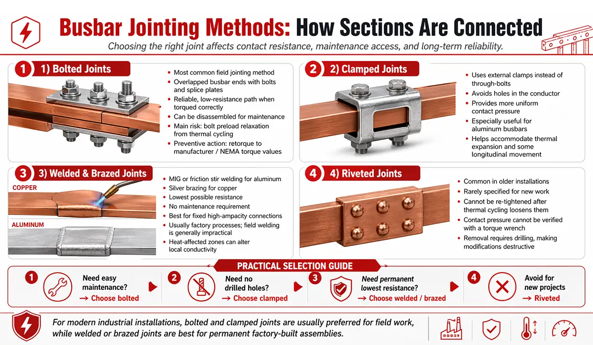
Busbar Jointing Methods: How Sections Are Connected
Busbars are often installed in separate sections because of handling limits, panel layout, or multi-bay switchgear arrangements. The way these sections are connected directly affects contact resistance, maintenance access, and long-term reliability.
Bolted joints are the most common method. Busbar ends are overlapped, drilled, and tightened with bolts or splice plates. When correctly torqued, they provide a reliable low-resistance connection and can be opened later for maintenance.
Clamped joints use external clamps instead of through-bolts. They can reduce drilling requirements and help maintain contact pressure, especially where thermal expansion or aluminum oxidation must be considered.
Welded or brazed joints offer very low resistance and are usually used for fixed, high-current connections. However, they are more suitable for factory fabrication than field installation because they are difficult to inspect, modify, or disassemble later.
Riveted joints are mostly found in older systems and are rarely preferred in modern busbar assemblies because they cannot be re-tightened easily after thermal cycling.
If you are looking for more information about busbar Jointing Methods
, it is recommended not to miss reading this article.
Busbar Protection: How Busbars Are Safeguarded Against Faults
Busbar faults are among the most severe events in a power system. The dominant protection scheme is high-impedance differential protection (ANSI 87B): it measures the vector sum of all currents entering and leaving the busbar zone. Under normal conditions this sum is zero; a busbar fault produces a large differential current that operates the relay in under 20 ms — making it both fast and highly secure.
For large substations with many feeders, low-impedance numerical differential relays process each zone CT independently, offering superior CT saturation stability and greater operational flexibility. Modern substations also deploy arc flash detection relays — combining optical sensors and current elements — that trip all circuit breakers within 5 ms of arc detection, minimizing incident energy below 4 cal/cm² per IEEE C37.20.7. IEC 61850 GOOSE messaging enables inter-panel tripping across the digital substation network, replacing hard-wired trip circuits entirely and accelerating busbar protection response in complex multi-panel installations.
Emerging Busbar Applications in EVs, Data Centers, and Renewable Energy
Busbars are no longer limited to traditional switchgear and distribution boards. Modern power systems increasingly use busbars where compact layout, high current capacity, low resistance, and reliable mechanical connection are required.
- Electric vehicles and battery systems: Busbars are used to connect battery cells, modules, inverters, and power electronics. In these applications, compact design, vibration resistance, insulation quality, and thermal performance are critical.
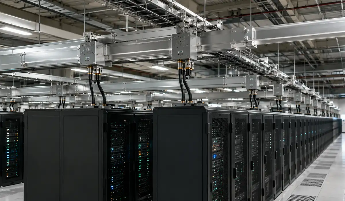
- Data centers: Busbar trunking and overhead busway systems help distribute power from UPS and power distribution equipment to server racks. Plug-in tap-off points can make future load changes easier than traditional cable-based distribution.
- Renewable energy and BESS: Solar farms, wind systems, and battery energy storage systems use AC and DC busbars to collect, combine, and distribute power. In low-voltage systems up to 1,000 V AC or 1,500 V DC, insulation coordination should be considered according to applicable standards such as IEC 60664-1.
These applications show why busbar design is becoming more important in modern electrical engineering. Material selection, cross-section sizing, insulation, spacing, joint quality, and accurate busbar processing all affect the safety and reliability of the final system.
Advantages of Electrical Busbars Over Cable Wiring
The question of busbar versus cable comes up early in any power distribution design, and the answer depends on application — but for high-current, multi-feeder installations, the busbar nearly always wins on total cost of ownership even where cable has a lower initial material cost.
High current capacity with low losses: A busbar’s large cross-sectional area and bolted joint interfaces carry very high currents with minimal voltage drop and I²R heating. Space efficiency: A single busbar system replaces what would otherwise be a large bundle of parallel cables, freeing significant conduit and tray space — particularly valuable in vertical risers in high-rise buildings. Modularity: Plug-in busway systems allow new loads to be added by tapping a new unit onto the duct without any shutdown, something that is simply not possible with fixed cable runs. Thermal management: The flat, open structure of a busbar dissipates heat more effectively than cables bundled inside conduit, where derating factors must be applied for every additional cable added to the bundle. Maintenance access: All connections are at a known location in a structured enclosure, accessible for IR scanning, torque checking, and insulation resistance testing without disturbing other circuits. Recyclability: Both copper and aluminum are 100% recyclable and extensively reclaimed at end of life — a meaningful sustainability consideration in large installations with decades-long service lives.
If you enjoyed learning about busbar advantages, investigating Victron busbar applications might also offer a similarly engaging and informative experience.
Conclusion: Why the Busbar Remains the Cornerstone of Electrical Power Distribution
A busbar is a rigid, low-impedance metallic conductor that collects current from power sources and distributes it to multiple loads — serving as the central node of every electrical distribution system, from low-voltage panelboards to extra high voltage transmission substations. Its working principle — maintaining near-uniform potential across all tap-off points while managing thermal, electromagnetic, and short-circuit stresses — makes it irreplaceable at every tier of the power infrastructure.
For engineers putting this knowledge into practice: download the Busbar Sizing Calculation Worksheet (Attachment A) for a worked numerical sizing example, or consult Attachment B for the Busbar Inspection and Maintenance Checklist. Understanding what is a busbar and how it works is the prerequisite for correct switchgear specification, substation busbar arrangement selection, and protection system design — contact a certified electrical engineer for bespoke switchgear and busbar specification on your next project.
FAQ


I’m new to electrical panels and I keep seeing the word busbar in drawings and product descriptions. Is a busbar just a metal conductor, or does it have a more specific function inside a distribution board?
A busbar is more than just a metal conductor. In an electrical panel or distribution board, a busbar works as a common power distribution path. It collects power from the incoming supply and distributes it to circuit breakers, feeders, or other electrical components. This helps make the panel layout cleaner, more compact, and easier to inspect compared with using many separate high-current cables.
I understand how busbars are used inside electrical panels, but what is busbar in power system applications? Is it only used in switchgear, or also in substations and larger networks?
In a power system, a busbar is a central conductive point used to collect and distribute electrical power between incoming and outgoing circuits. It can connect transformers, generators, feeders, circuit breakers, and protection equipment in switchgear, substations, distribution boards, and industrial power networks. In larger power systems, busbars help organize power flow, simplify switching operations, and allow multiple circuits to connect to the same electrical node safely and efficiently.