





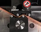
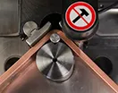
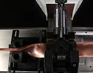
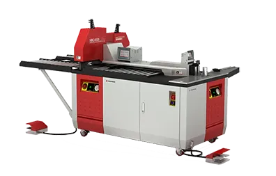
In the video below, you can watch the complete copper busbar fabrication and production process.
If you’d rather listen than read, feel free to play the audio file below for the rest of this article.
What Is a Busbar? Types, Applications & Benefits
A busbar (also written as “bus bar”) is a metallic strip or bar, typically made of copper or aluminum, that conducts electricity inside switchgear, panel boards, substations, and other electrical distribution systems. Unlike insulated cables, busbars offer higher current-carrying capacity, minimal voltage drop, and excellent heat dissipation. A copper busbar is the most common choice for compact, high-current designs, while aluminum suits long runs and weight-sensitive projects.
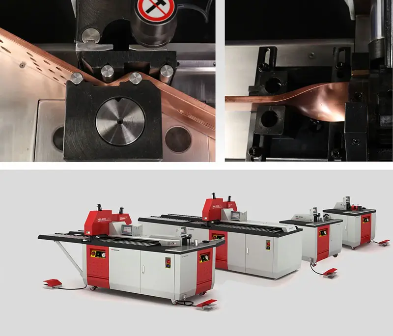
Before you read the rest of this guide, take a look at the busbar machine range that covers every operation described below.
This guide explains the complete busbar manufacturing process, from raw material selection to final testing, so you can understand how a finished busbar assembly is produced, which quality checks matter, and what it costs to set up a production line.
Why Choose Busbars Over Traditional Cables?
- Higher Current Capacity: A 10 mm × 100 mm copper busbar can carry well over 1,500 A in typical conditions, replacing several parallel cables
- Better Heat Dissipation: Larger surface area reduces temperature rise by 30-40%
- Space Efficiency: Requires up to 60% less space than equivalent cable installations
- Lower Installation Cost: Faster installation with fewer connection points
- Improved Reliability: Fewer joints mean fewer failure points
For a comprehensive understanding of What is a Busbar?, we highly recommend reviewing this article.
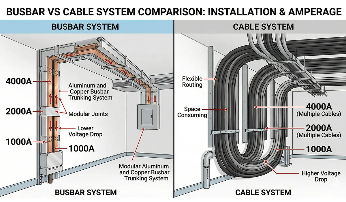
What Is a Copper Busbar? Copper vs Aluminum Busbars
A copper busbar is a conductor made from electrolytic tough pitch (ETP) copper, valued for its conductivity, strength, and natural corrosion resistance. The table below compares copper busbars with aluminum busbars.
| Property | Copper Busbar | Aluminum Busbar |
|---|---|---|
| Electrical Conductivity | 100% (Reference Standard) | 61% of Copper |
| Weight | 8.96 g/cm³ (Heavy) | 2.70 g/cm³ (70% Lighter) |
| Cost per kg | Higher (3-4× aluminum) | Lower (Budget-friendly) |
| Thermal Expansion | 16.5 × 10⁻⁶/°C | 23.1 × 10⁻⁶/°C |
| Corrosion Resistance | Excellent (Forms protective patina) | Good (Requires coating) |
| Best Applications | High-current, compact spaces, marine | Long runs, overhead, weight-sensitive |
Pro Tip: For the same current capacity, aluminum busbars must be approximately 1.6× wider than copper busbars. Calculate your space constraints before material selection.
Further exploration of Copper vs Aluminum Busbar can be found in the following recommended reading.
Busbar Design Basics
Good busbar design starts with the current rating, the allowed temperature rise, short-circuit withstand strength, and the available space. Engineers size the cross-section first, then define phase spacing, support insulators, and joint locations. A well-planned bus bar system keeps joints few, keeps bends gentle, and leaves enough air gap for cooling. Design decisions made at this stage directly affect how easy the busbar is to cut, punch, and bend later.
Step-by-Step Busbar Manufacturing Process
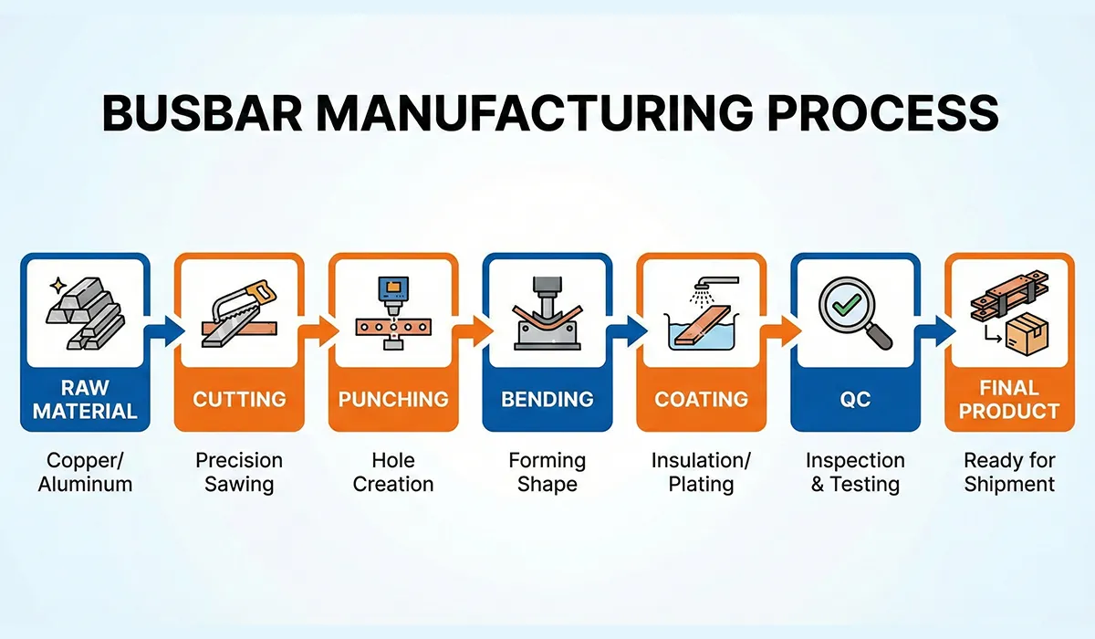
The busbar manufacturing machine process (also called busbar fabrication or busbar production) involves six critical stages. Each step requires precision to ensure the finished bus bar meets electrical, mechanical, and safety standards.
Step 1: Raw Material Selection & Preparation
The journey begins with selecting the right conductive material. Copper busbar manufacturing typically uses ETP copper with 99.9% purity (C11000 grade), while aluminum applications use 6101-T6 or 6063-T6 alloys.
Material Selection Criteria:
| Factor | Considerations |
|---|---|
| Current Rating | >800A: Copper preferred <800A: Aluminum cost-effective |
| Environment | Marine/Coastal: Copper with tin coating Indoor/Dry: Either material acceptable |
| Space Constraints | Compact panels: Copper (smaller cross-section) Large substations: Aluminum (weight advantage) |
| Budget | Initial cost: Aluminum wins Lifecycle cost: Copper more economical |
Standard Stock Sizes:
- Thickness: 3mm, 5mm, 6mm, 8mm, 10mm, 12mm
- Width: 20mm, 25mm, 30mm, 40mm, 50mm, 60mm, 80mm, 100mm, 120mm, 150mm, 200mm
- Length: Standard bars come in 2m, 3m, 4m, or 6m lengths
Step 2: Cutting – Precision Sizing
Raw busbar stock is cut to the required lengths. Modern CNC cutting systems hold tolerances within ±0.1mm, which is critical for proper assembly.
Cutting Methods Comparison:
| Method | Accuracy | Speed | Best For |
|---|---|---|---|
| Manual Hacksaw | ±1mm | Slow | Prototype/Repair work |
| Hydraulic Shear | ±0.5mm | Fast | High-volume, straight cuts |
| CNC Cutting | ±0.1mm | Medium | Precision work, complex shapes |
| Bandsaw | ±0.3mm | Medium | Thick busbars (>10mm) |
Common Cutting Mistakes:
- Burr formation on cut edges (requires deburring)
- Material deformation from excessive blade pressure
- Incorrect measurements leading to scrap (measure twice, cut once!)
Step 3: Punching – Creating Connection Points
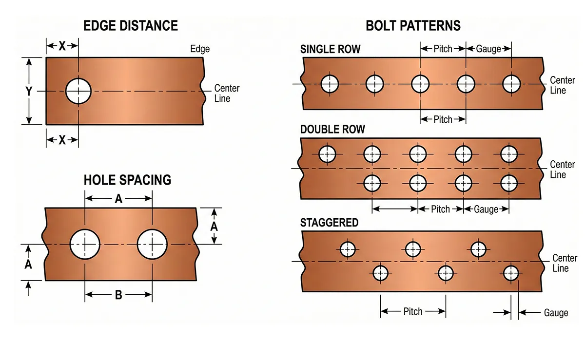
After cutting, busbars need precisely positioned holes for bolted connections. Automatic or CNC punching creates these holes with exact positioning and clean edges.
Critical Punching Parameters:
| Parameter | Standard Values | Why It Matters |
|---|---|---|
| Hole Diameter | M6: 6.5mm M8: 9mm M10: 11mm M12: 13mm |
Bolt clearance + thermal expansion |
| Edge Distance | Minimum = 2× hole diameter | Prevents tearing during tightening |
| Hole Spacing | Minimum = 3× hole diameter | Maintains mechanical strength |
| Punch Tolerance | ±0.1mm for CNC ±0.3mm for manual |
Alignment with mating components |
Punching Force Calculation:
Required tonnage = Perimeter × Thickness × Material Shear Strength
Example: For 13mm hole in 10mm copper busbar:
Perimeter = π × 13mm = 40.8mm
Force = 40.8mm × 10mm × 250 N/mm² = 102,000 N ≈ 10.4 tons
Step 4: Bending & Forming – Shaping the Busbar
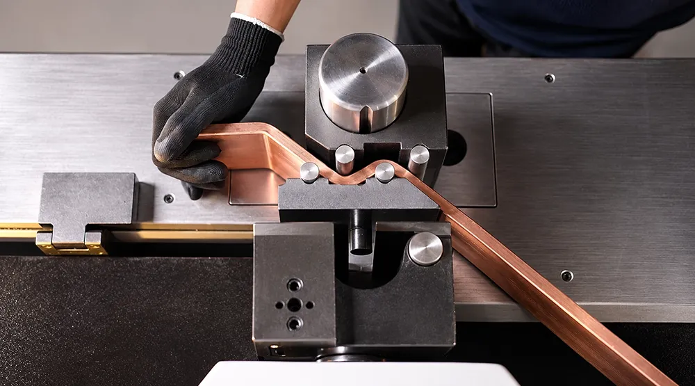
copper bending is perhaps the most critical step in the process. Improper bending can cause stress fractures, reduced current capacity, or installation failures.
Bending Methods:
- Manual bending: Suitable for small workshops, up to 8mm thickness, angle accuracy ±2°
- Hydraulic bending: Handles 3-12mm thickness, angle accuracy ±1°, consistent force application
- CNC bending: Programmable angles, ±0.5° accuracy, ideal for complex shapes
- Portable hydraulic bending: On-site modifications, up to 10mm
Bend Radius Guidelines (Critical for Avoiding Cracks):
| Busbar Thickness | Minimum Bend Radius | Recommended Radius | Maximum Bend Angle |
|---|---|---|---|
| 3mm | 4.5mm (1.5t) | 6mm (2t) | 90° |
| 5mm | 7.5mm (1.5t) | 10mm (2t) | 90° |
| 8mm | 12mm (1.5t) | 16mm (2t) | 90° |
| 10mm | 15mm (1.5t) | 20mm (2t) | 90° |
| 12mm | 18mm (1.5t) | 24mm (2t) | 90° |
Note: ‘t’ = thickness. Formula: Minimum Radius = 1.5 × thickness
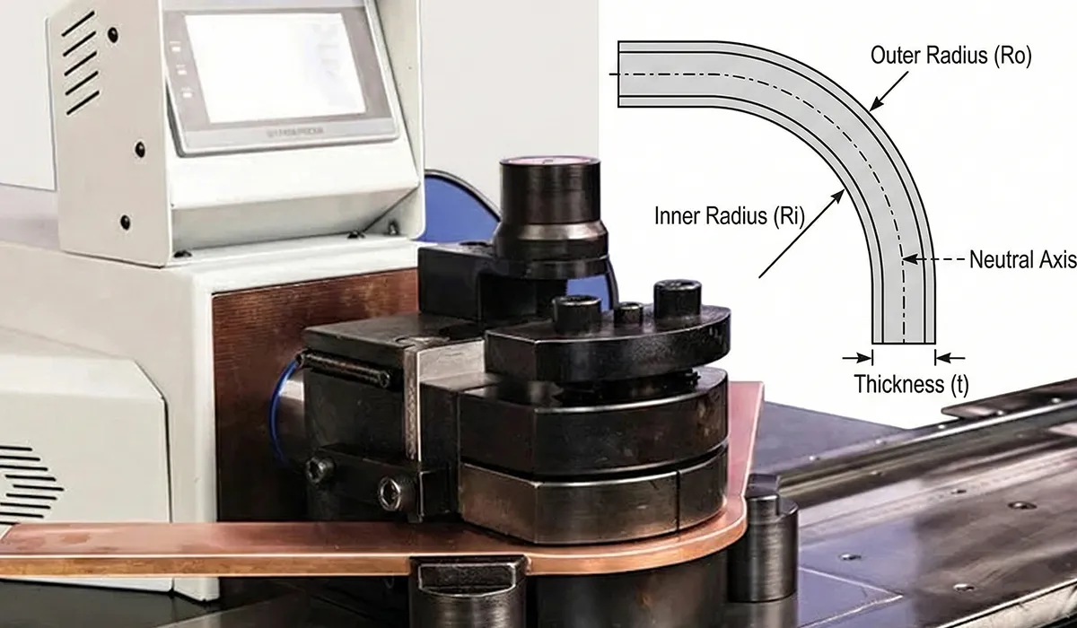
Bending Best Practices:
- Always bend perpendicular to the grain direction of the material
- Use proper tooling with radius matched to busbar thickness
- Anneal copper before bending if multiple complex bends are required
- Check for cracks after bending using dye penetrant inspection
- Account for springback: overbend by 2-5° then release to final angle
Step 5: Surface Treatment & the Busbar Plating Process
Proper surface treatment extends busbar lifespan by 3-5× and ensures reliable electrical connections. Copper busbar coating prevents oxidation, while aluminum requires treatment to prevent galvanic corrosion.
How the Busbar Plating Process Works:
- Degreasing: An alkaline cleaner removes oils and cutting residue
- Acid pickling: Removes surface oxides so the plating bonds properly
- Rinsing: Clean water rinse between every chemical bath
- Plating: Tin, nickel, or silver is deposited electrochemically to the specified thickness
- Final rinse and drying: Prevents staining and water marks
- Inspection: Thickness and adhesion are verified (see Step 6)
Common Surface Treatment Options:
| Coating Type | Thickness | Applications | Cost |
|---|---|---|---|
| Tin Plating | 5-10 μm | General purpose, indoor panels Max temp: 150°C |
$ |
| Nickel Plating | 3-8 μm | High-temperature applications Max temp: 250°C |
$$ |
| Silver Plating | 2-5 μm | Low-resistance connections Medical, aerospace |
$$$$ |
| Powder Coating | 50-100 μm | Insulated busbars Color-coded systems |
$$ |
| Anodizing (Aluminum) | 10-25 μm | Corrosion protection Outdoor installations |
$$ |
| Bare Copper | 0 | Dry indoor only Requires regular cleaning |
– |
Selection Guide:
- Indoor residential/commercial: Tin-plated copper (cost-effective, reliable)
- Industrial high-temperature: Nickel-plated copper (withstands heat)
- Marine/coastal environments: Tin-plated copper + epoxy sealing
- Data centers/critical systems: Silver-plated copper (lowest contact resistance)
- Outdoor substations: Anodized aluminum or bare copper with periodic maintenance
Step 6: Quality Control, Testing & Busbar Assembly
Every busbar production line must apply rigorous quality control to ensure safety and performance. Industry standards require both visual inspection and electrical testing. Once parts pass inspection, they move to busbar assembly, where bars, insulators, and fasteners are put together and torqued to specification.
Required Quality Checks:
| Test Type | Method | Acceptance Criteria |
|---|---|---|
| Dimensional Check | Digital calipers, CMM | ±0.5mm tolerance |
| Visual Inspection | 100% inspection under light | No cracks, burrs, or scratches >0.5mm deep |
| Conductivity Test | 4-wire resistance measurement | ≤105% of theoretical resistance |
| Bend Test (Sample) | 90° bend around mandrel | No visible cracks after bending |
| Coating Thickness | X-ray fluorescence gauge | Within specified range ±1μm |
| Temperature Rise Test | Rated current until thermal stability | Within the limits of IEC 61439-1 (see table below) |
Documentation Requirements:
- Material certificates (mill test reports)
- Dimensional inspection reports
- Electrical test results
- Plating thickness certificates
- Traceability markings (batch number, date code)
Cutting, Punching & Bending Capacity Guide
Choosing the right capacity for each operation is the key to a smooth busbar production line. The tables below summarize typical capacities for each level of automation.
1. Cutting Capacity
| Level | Capacity | Best For |
|---|---|---|
| Manual Cutter | Up to 10mm × 125mm | Small workshops, low volume |
| Hydraulic Shear | Up to 12mm × 200mm | Medium production |
| CNC Cutting | Up to 15mm × 250mm | High precision, automation |
2. Punching Capacity
| Level | Capacity | Production Rate |
|---|---|---|
| Manual Punch | Ø13mm in 8mm copper | 5-10 holes/hour |
| Hydraulic Punch | Ø20mm in 12mm copper | 20-30 holes/hour |
| CNC Punching | Ø30mm in 15mm copper | 100+ holes/hour |
3. Bending Capacity
| Level | Capacity | Angle Accuracy |
|---|---|---|
| Manual Bending | Up to 8mm × 80mm | ±2° |
| Hydraulic Bending | Up to 12mm × 150mm | ±1° |
| CNC Bending | Up to 15mm × 200mm | ±0.5° |
| Portable Hydraulic | Up to 10mm × 100mm | ±1.5° |
4. Combined 3-in-1 Units
| Specification | Entry Level | Professional |
|---|---|---|
| Max Cutting Capacity | 8mm × 100mm | 12mm × 200mm |
| Max Punching | Ø13mm in 8mm | Ø20mm in 12mm |
| Max Bending | 8mm × 80mm, 90° | 12mm × 150mm, 90° |
| Best For | Panel builders, contractors | Medium-scale busbar production |
Cost Analysis: Setting Up a Busbar Production Line
Understanding the investment required for copper busbar manufacturing or aluminum busbar production is crucial for business planning. Here is a breakdown of setup costs and ROI expectations.
If the information on cost analysis was useful, you may also like to read about the value of corner forming.
Initial Investment Breakdown
| Setup Level | Small Workshop | Medium Production | Large Scale |
|---|---|---|---|
| Equipment & Tooling | $15,000-$30,000 (3-in-1 unit + tools) |
$80,000-$150,000 (Separate cutting, punching, bending lines) |
$300,000-$800,000 (CNC automated line) |
| Facility | 200-300 m² $2,000-$5,000/month |
500-800 m² $5,000-$12,000/month |
1,500+ m² $15,000-$30,000/month |
| Raw Materials (Initial Stock) | $10,000-$20,000 | $50,000-$100,000 | $200,000-$500,000 |
| Personnel (Annual) | 2-3 workers $60,000-$90,000 |
8-12 workers $240,000-$400,000 |
25-40 workers $750,000-$1.5M |
| Utilities & Operating | $2,000-$4,000/month | $8,000-$15,000/month | $25,000-$50,000/month |
| Quality Control Equipment | $3,000-$8,000 | $15,000-$35,000 | $50,000-$150,000 |
| TOTAL FIRST-YEAR COST | $120,000-$200,000 | $550,000-$900,000 | $2M-$4.5M |
Production Capacity & Revenue Potential
| Setup Level | Monthly Production | Revenue/Month | ROI Timeline |
|---|---|---|---|
| Small Workshop | 500-1,000 kg 1,000-2,000 pieces |
$15,000-$35,000 | 18-24 months |
| Medium Production | 3,000-6,000 kg 6,000-12,000 pieces |
$90,000-$200,000 | 12-18 months |
| Large Scale | 15,000+ kg 30,000+ pieces |
$450,000-$1M+ | 24-36 months |
Profit Margin Analysis:
- Raw Material Cost: 60-70% of selling price (copper prices fluctuate)
- Labor & Overhead: 15-20%
- Profit Margin: 10-25% depending on value-added services (coating, custom shapes)
Cost Reduction Strategies:
- Buy copper in bulk during price dips (hedge against market volatility)
- Invest in CNC automation to reduce labor costs long-term
- Minimize scrap through precise cutting optimization software
- Offer value-added services (coating, assembly) for higher margins
- Establish long-term contracts with electrical panel builders
Industry Standards & Quality Certifications
Professional busbar manufacturing must comply with international electrical standards to ensure safety, performance, and market acceptance.
Key International Standards
| Standard | Region | Covers |
|---|---|---|
| IEC 61439-1/2 | International | Low-voltage switchgear assemblies, busbar temperature rise, short-circuit performance |
| UL 857 | North America | Busway systems, current ratings, construction requirements |
| IEEE 605 | USA | Bus design in substations, mechanical and electrical stresses |
| BS EN 60439 | UK/Europe | Type-tested and partially type-tested assemblies |
| IS 8623 | India | Copper busbars for electrical purposes |
| GB/T 5585 | China | Electrical copper busbars specifications |
Required Certifications for Commercial Production
- ISO 9001: Quality management system (mandatory for B2B sales)
- ISO 14001: Environmental management (increasingly required)
- UL Listing: Required for North American markets
- CE Marking: Mandatory for European Union sales
- RoHS Compliance: Restriction of hazardous substances in coatings
This article serves as a valuable resource for those seeking detailed information on CE marking.
Temperature Rise Limits (IEC 61439-1)
| Component | Max Temperature Rise | Absolute Max Temp |
|---|---|---|
| Bare copper/aluminum busbars | 70 K | 105°C |
| Tin-plated busbars | 65 K | 100°C |
| Nickel-plated busbars | 80 K | 115°C |
| Insulated/enclosed busbars | 50 K | 85°C |
Common Issues & Troubleshooting in Busbar Fabrication
Issue 1: Burrs and Sharp Edges After Cutting
Symptoms: Rough edges, metal shavings, difficulty handling
Causes: Dull cutting blades, incorrect cutting speed, improper blade clearance
Solutions: Replace or sharpen blades regularly (every 500-1000 cuts), use deburring tools or files immediately after cutting, adjust blade clearance to 5-7% of material thickness, consider CNC cutting for cleaner edges.
Issue 2: Cracks Appearing After Bending
Symptoms: Visible cracks on outer bend radius, material failure
Causes: Bend radius too small (below 1.5× thickness), bending parallel to grain direction, work-hardened material from prior operations
Solutions: Always use a bend radius of at least 2× thickness, anneal copper at 500-700°C if multiple bends are required, bend perpendicular to rolling direction, inspect with dye penetrant testing after critical bends.
Issue 3: Inconsistent Hole Positioning
Symptoms: Holes don’t align with mating components, assembly difficulties
Causes: Manual measurement errors, punch drift during operation, material movement during punching
Solutions: Upgrade to CNC punching for ±0.1mm accuracy, use digital templates and jigs for manual punching, clamp material securely during punching, implement first-article inspection for each batch.
Issue 4: Plating Delamination or Peeling
Symptoms: Coating separates from base metal, reduced corrosion protection
Causes: Poor surface preparation before plating, contamination (oils, oxides), inadequate plating thickness
Solutions: Clean with alkaline degreaser before plating, use acid pickling to remove oxides, ensure minimum 5μm plating thickness, test adhesion with tape test (ASTM D3359).
Issue 5: Excessive Temperature Rise in Service
Symptoms: Busbar exceeds 70K temperature rise, insulation damage
Causes: Undersized busbar for current load, poor connection quality (high resistance), inadequate ventilation
Solutions: Recalculate busbar size using IEC 61439-1 guidelines, torque connections to specification, use thermal imaging to identify hot spots, increase busbar cross-section or improve cooling.
Conclusion: Mastering Busbar Manufacturing in 2026
The journey of busbar manufacturing, from raw copper to a precision-engineered electrical conductor, requires understanding material science, choosing the right cutting, punching, and bending capacity, maintaining strict quality standards, and continuously optimizing the process. Material selection between copper and aluminum depends on current requirements, budget, and environment. Precision in cutting, punching, and bending directly affects final product quality and safety. CNC automation offers superior accuracy but requires higher investment. Quality control and compliance with IEC/UL standards is non-negotiable for commercial production, with ROI timelines ranging from 12-36 months depending on production scale.
Whether you are a panel builder looking to bring busbar fabrication in-house, an electrical contractor exploring business expansion, or a producer optimizing an existing line, understanding the complete busbar production process pays off in quality, efficiency, and profitability.
Ready to start? Consider these actions: First, assess your requirements by calculating expected monthly volume, typical busbar sizes, and budget. Second, request demonstrations from reputable suppliers and compare capacity, accuracy, and after-sales support. Third, start small with a 3-in-1 unit, then add dedicated lines as volume grows. Fourth, invest in operator training, because precision work requires skilled personnel. Fifth, plan for ISO 9001 and relevant electrical standards compliance early. For technical questions about busbar sizing or custom projects, consult certified electrical engineers to ensure your setup meets both performance and safety standards.
Frequently Asked Questions (FAQ)



Rate this article
Choose a rating from 1 to 5 stars.
5.0 out of 5 — 1 vote
0 Comments
No comments yet. Be the first to comment.