


For your convenience, if you prefer listening, you can listen to the rest of this article via the audio file below.
What Is an LV Busbar and What Does It Do Inside a Switchgear Panel?
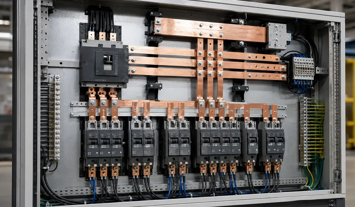
An LV busbar is the low-resistance conductor that receives power from the incomer and distributes it to the outgoing functional units. It is the main conductor rail of the panel, and every feeder depends on it. A typical LV switchgear assembly uses four conductor families: the main busbar, the sub-busbar or riser, the neutral busbar, and the earthing busbar. Each one has a different electrical and protective role, so they are sized and verified separately.
For a comprehensive understanding of busbar design and applications, we highly recommend reviewing this article on what is a busbar.
Compared with cables, an LV busbar offers lower impedance, firmer mechanical restraint, cleaner routing, and more predictable behaviour during a short circuit. That is why high-current panels use bars instead of large cable bundles.
If you are looking for more information about low voltage switchgear assemblies, it is recommended not to miss reading this article on switchgear fundamentals.
Types of Busbar Materials Used in LV Switchgear Panels
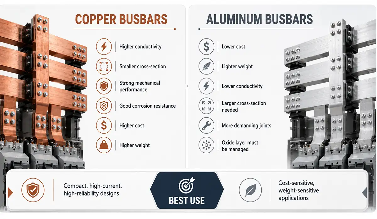
Material choice shapes conductivity, weight, joint reliability, corrosion behavior, and fault endurance. For most LV switchgear busbar design work, the decision is copper vs aluminum, not metal vs cable.
Copper supports compact layouts because it has about 100% IACS conductivity, while aluminum is about 61% IACS and usually needs a larger cross-section for equal resistance. Further exploration of electrical conductivity and resistivity can be found in the following recommended reading: electrical conductivity and resistivity.
Aluminum becomes attractive when board size is large, conductor length is long, or weight matters more than minimum volume. Copper stays dominant where joint stability and compactness matter more. This article serves as a valuable resource for those seeking detailed information on types of electrical power distribution boards: Types of Electrical Power Distribution Board.
Surface finish also matters. Bare, tin-plated, and silver-plated busbars behave differently at interfaces, especially where low contact resistance and oxidation control are critical.
Copper Busbars
Copper busbars remain the default for most copper busbar switchgear designs because they combine high conductivity, strong mechanical behavior, good corrosion resistance, and smaller required sections. ETP high-conductivity copper is the usual baseline, while harder tempers are selected when additional mechanical strength is needed. This article serves as a valuable resource for those seeking detailed information on copper conductor properties and uses.
Aluminum Busbars
For engineers asking what is the difference between copper and aluminum busbars in switchgear, aluminum offers lower mass and lower material cost, but it also brings lower conductivity and more demanding joint practice because oxide films and dissimilar-metal interfaces can reduce long-term reliability if not controlled. If you are looking for more information about galvanic corrosion at dissimilar metal joints, it is recommended not to miss reading this article on galvanic corrosion.
High Thermal Conductivity: Why It Matters in Busbar Material Selection
Busbar material is usually compared on electrical conductivity, but thermal conductivity deserves equal attention, because the whole rating problem is a heat problem. Copper conducts heat at roughly 400 W/m·K, nearly twice the value of aluminium at about 230 W/m·K. The two properties move together, since the same free electrons carry both charge and heat
High thermal conductivity does two useful things inside a panel. First, it spreads heat along the bar instead of letting it collect in one place. Because both metals conduct heat well, the temperature rise inside the bar stays low and spreads across the whole conductor, which reduces the effect of any hot spot. Second, it pulls heat away from bolted joints and device terminals, which are the hottest points in most assemblies.
There is an important limit to this benefit, and it is where many material comparisons go wrong. Internal thermal conductance is not what governs busbar temperature, because loss densities are relatively low and both metals conduct heat well. The heat transfer from the bar to the surrounding air is the real bottleneck, with natural convection contributing around 60% and radiation around 40%.
The practical meaning: high thermal conductivity protects you against local hot spots, but surface area, surface emissivity, spacing, and ventilation decide the final current rating. Choosing copper does not remove the need for derating.
| Property | ETP Copper | Aluminium |
|---|---|---|
| Thermal Conductivity | ~390–400 W/m·K | ~230–237 W/m·K |
| Electrical Conductivity | ~100% IACS | ~61% IACS |
| Density | 8.9 g/cm³ | 2.7 g/cm³ |
| Section for Equal Current | Baseline | ~1.5–1.6 × Larger |
| Hot-Spot Spreading | Excellent | Good |
| Joint Discipline Needed | Standard | Higher (Oxide Control) |
Note that aluminium’s lower thermal conductivity is partly offset in practice, because the larger cross-section it needs also gives more surface area for cooling. Judge the material by the finished bar, not by the property table alone.
Tin-Plated and Silver-Plated Busbars
Tin plating is commonly used to limit oxidation and improve joint consistency, while silver plating is favored where very low interface resistance, stable contact performance, and higher-temperature terminations are justified. Plating mainly improves the connection surface; it does not replace correct torque, overlap, or pressure. For a comprehensive understanding of flexible busbar options and their surface treatments, we highly recommend reviewing this article on flexible busbar types, sizing, and standards.
Busbar Sizing and Current Rating for LV Panels (Quick Reference)
Sizing starts with rated current, but the final answer depends on enclosure heating, ventilation, conductor arrangement, and fault duty. A sound check covers continuous current, ambient correction, permissible temperature rise, and the way nearby bars or partitions reduce cooling. At larger sections, skin effect and proximity effect also reduce the value of simple area-based rules.
Cross-section alone never tells the whole story, so an LV busbar must be sized against both thermal and mechanical limits. A bar that carries its continuous current safely can still fail the fault-duty check.
The table below is for quick screening only.
| Copper busbar size | Area (mm²) | Indicative current rating* |
|---|---|---|
| 25 × 3 mm | 75 | 190–210 A |
| 40 × 5 mm | 200 | 400–440 A |
| 60 × 10 mm | 600 | 860–940 A |
Reference conditions: single flat bar, still air, 40 °C ambient, ΔT = 35 °C. Derate for higher ambient, enclosed mounting, poor ventilation, or stacked bars.
This article serves as a valuable resource for those seeking detailed information on busbar sizing methods: Busbar Sizing Guide.
Short-Circuit Withstand Capability of Busbars
Short-circuit performance has two sides: thermal survival and electrodynamic survival. Both must be checked because high fault current heats the bar and also pushes it mechanically.
The thermal side is about I²t energy during the clearing time. The dynamic side is about peak magnetic force between parallel conductors during the first current peak. Further exploration of short circuit current effects can be found in the following recommended reading.
Support span, phase spacing, bar stiffness, and support strength are therefore just as important as conductor area. A narrow fault window can still create severe peak loading.
In an LV switchgear assembly, the declared short-circuit rating must match the verified assembly configuration, not a generic bar size alone.
Thermal Withstand Current (Icw)
The core of any busbar short circuit withstand current calculation is the adiabatic relationship between fault current, duration, and cross-section. In simplified form, designers use (A = I √t / k), then confirm that conductor temperature stays within acceptable limits for the material and assembly. If you are looking for more information about power factor and its effect on current ratings, it is recommended not to miss reading this article on power factor.
Dynamic (Electrodynamic) Withstand and Peak Current (Ipk)
Dynamic withstand is driven by the first peak current, which creates Lorentz forces between conductors. In IEC-based LV practice, engineers often use a practical approximation of Ipk ≈ 2.2 × Icw for higher-duty assemblies, then check support spacing, cleats, deflection, and mechanical stress. Thermal vs dynamic design is a critical contrast, not a paperwork detail. This article serves as a valuable resource for those seeking detailed information on Lorentz force in electrical systems.
Verified vs. Calculated Withstand (Type Test vs. Calculation)
IEC 61439 allows design verification through testing, comparison with a verified reference design, or calculation where the method is permitted and the geometry is adequately bounded. The important point is traceability: declared fault level withstand capacity must belong to the complete assembly, not only to an isolated conductor.
Busbar Insulation, Clearances, and Creepage Distances
Clearance is the shortest distance through air. Creepage is the shortest path along an insulating surface. They solve different failure modes and must not be confused. If you are looking for more information about creepage and electrical clearance distances, it is recommended not to miss reading this article on creepage distances.
For anyone checking busbar spacing and clearance requirements in switchgear, the required values depend on rated insulation voltage, impulse withstand category, pollution degree, material group, and altitude.
| Worked Example Input | Verified Public Output |
|---|---|
| Ui = 1000 V | LV Equipment Scope Applies |
| Overvoltage Category = III | Uimp = 8 kV |
| Pollution Degree = 3 | Industrial Micro-Environment |
| Clearance Result | 8 mm at ≤ 2000 m |
Heat-shrink sleeving, epoxy coating, boots, and barriers can improve insulation coordination, but they do not remove the need for correct design distances and workmanship. Bare vs insulated systems remain a real design contrast.
Pollution degree matters because dust, humidity, and condensation increase tracking risk. LV MCC rooms and industrial workshops are often more demanding than clean electrical rooms.
Note: the table above is a clearance result at Ui = 1000 V and overvoltage category III. The creepage table below uses 400 V working voltage. Clearance and creepage are independent requirements, and creepage is never smaller than clearance at the same voltage.
| Working voltage | Pollution degree 2 | Pollution degree 3 |
|---|---|---|
| 400 V | ~2.0 mm creepage (MG I) / 2.8 mm (MG II) | ~4.0–5.0 mm creepage |
| 690 V class* | Commonly based on 630 V row in IEC tables | Commonly based on 630 V row in IEC tables |
*IEC-based guides commonly allow 660/690 V designs to use the 630 V creepage row in the tabulation note, but the final selection still depends on material group and insulation concept.
Busbar Panel Design: Arrangement and Physical Layout in LV Switchgear
Busbar panel design is where the electrical calculation becomes a real assembly. Layout decides whether the design stays buildable, cool-running, and maintainable over its service life. It covers bar routing, compartment boundaries, cable access, support spacing, and the space left for future feeders.
Good layout lowers impedance and temperature rise while keeping safe access for inspection and modification. Poor layout does the opposite, even when the nominal bar size is correct on paper. There is also a direct commercial trade-off: a larger main busbar takes more cabinet volume, which reduces the number of outgoing modules unless the cabinet height or internal arrangement is changed.
This is the point where routing direction, form of separation, and phase identification stop being drafting choices and become reliability choices. The most robust low voltage distribution panel busbars are designed as one complete system: conductors, supports, insulation, joints, and compartment logic together.
For a comprehensive understanding of ground bus bar design and its role in system layout, we highly recommend reviewing this article on ground bus bars.
Horizontal Busbar vs Vertical Busbar: How to Choose the Layout
In most LV switchgear, horizontal and vertical busbars are not competing options. They work together. The horizontal busbar is the main distribution bus, with one set per phase running through every cubicle in the lineup, and a vertical busbar is tapped off it inside each cubicle to serve the incomer, feeder, bus-coupler, or motor starter circuit. So the real design question is how each one is used, not which one is better.
The horizontal busbar is the backbone. It carries the full assembly current from the incomer along the lineup, so it is normally the largest section in the panel. It simplifies section-to-section transfer and gives a longer, well-ventilated path for heat to spread.
The vertical busbar (also called the riser) is the distribution spine. It brings power from the main horizontal bar down to each outgoing unit, and its design affects current rating, short-circuit strength, insulation support, and how modular the platform can be. Where a lineup has bars at different heights, a bus riser connects them vertically between panels. Risers carry less current than the main bar but need tighter support discipline, because they are long, slender, and mounted close to functional units.
One point that is often confused: run direction and bar mounting orientation are two different things. A horizontal main bar can still be mounted edgewise. Mounting matters thermally, because a vertically mounted bar dissipates heat better than a horizontally mounted one due to convection. Always state both the run direction and the mounting face in the design file.
| Design Point | Horizontal Main Busbar | Vertical Busbar / Riser |
|---|---|---|
| Typical Role | Main Bus Through the Lineup | Feeds Outgoing Units in One Column |
| Current Carried | Full Assembly Rating | Section or Feeder Rating |
| Usual Location | Top or Rear Bus Chamber | Behind Functional Unit Compartments |
| Main Risk | Cabinet Volume and Section Transfer | Support Spacing and Access |
| Best Suited to | Main Distribution Boards, Switchboards | MCCs, Feeder Columns |
| Key Check | Section Transfer Joints, Cooling Path | Cleat Spacing, Deflection, Insulation Support |
Practical rule: size the horizontal bar for the incomer rating plus future margin, then size each riser for its own column demand. Copying the main bar dimension into every riser wastes copper and cabinet space.
For a comprehensive understanding of motor control center panel design, we highly recommend reviewing this article.
Busbar Segregation and Form of Separation
Forms 1 to 4b describe how busbars, functional units, and terminals are separated. Higher separation generally improves safety, limits fault propagation, and reduces maintenance exposure, but it also increases complexity, size, and cost. Form 4 separation is common where continuity and safer live-side intervention matter. This article serves as a valuable resource for those seeking detailed information on terminal bus bar configurations and separation: Terminal Bus Bar Guide.
Phase Arrangement and Color Coding
Phase busbar and neutral busbar identification should remain consistent throughout the assembly. In IEC practice, engineers typically use L1-L2-L3 with brown, black, and grey for phases, blue for neutral, and green/yellow for PE, then lock that scheme into drawings, labels, and test documentation. Further exploration of electrical wiring color code standards can be found in the following recommended reading.
Installation, Jointing, and Torque Requirements for Busbars
Most busbar failures begin at joints, not in the straight conductor. That makes overlap length, surface condition, washer choice, and tightening method critical.
For anyone addressing busbar joint resistance and contact pressure, the rule is simple: stable pressure keeps resistance low; unstable pressure creates heat. Aluminum joints need extra care because oxide films form quickly. If you are looking for more information about Victron busbar systems and joint hardware options, it is recommended not to miss reading this article on Victron busbars.
Typical example values from industry documentation show M8 ≈ 17.5 Nm and M10 ≈ 30 Nm on busbar connections, but exact torque must follow the tested hardware, surface condition, and manufacturer instruction set.
A practical pre-delivery checklist is:
- verify contact faces are clean and flat
- confirm correct hardware and washer stack
- apply approved compound on aluminum interfaces
- recheck torque with documented values
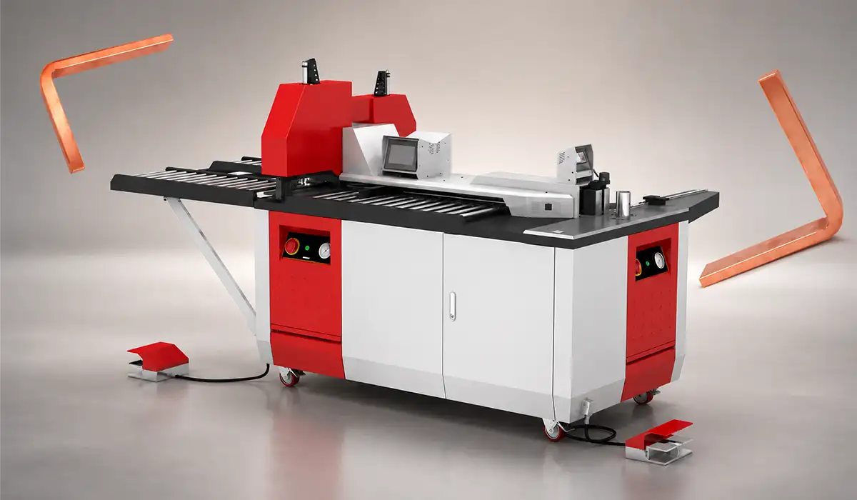
Achieving flat, burr-free contact faces begins at the fabrication stage — a precision busbar machine that cuts and punches to tight tolerances reduces the joint preparation work required during assembly.
Long runs also need thermal-expansion allowance, especially in larger switchboards and busbar trunking system interfaces. This article serves as a valuable resource for those seeking detailed information on thermal expansion in engineering applications.
Common Failures and Maintenance of Busbars in LV Switchgear
The most common failure mode is overheating at a joint caused by loose hardware, oxidation, creep, or uneven pressure. The conductor may be adequately sized while the connection is failing.
Contamination, conductive dust, or moisture can also trigger tracking and flashover, especially where busbar insulation material is damaged or clearance margins are already small.
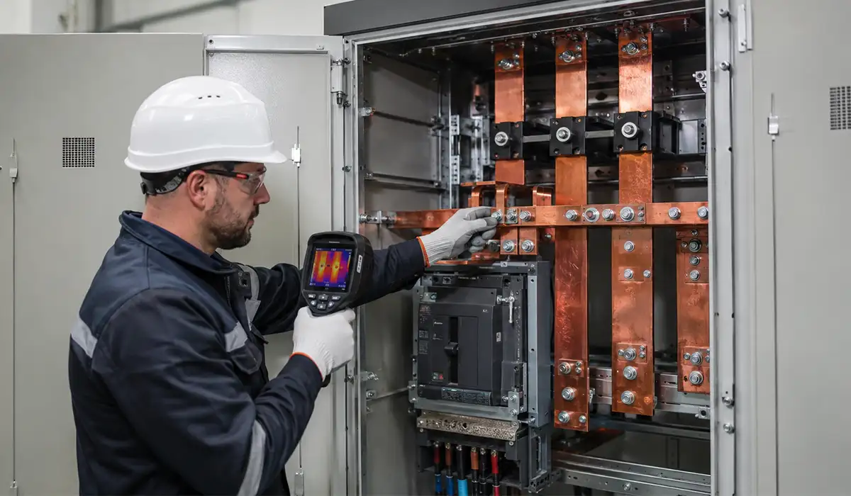
If the question is how to prevent busbar overheating in electrical panels, the best answers are disciplined torque control, clean interfaces, correct loading, and periodic thermography under meaningful load. If you are looking for more information about infrared thermography in electrical maintenance, it is recommended not to miss reading this article on infrared thermography.
IR inspection is now widely treated as a core maintenance tool because it reveals hot joints, imbalanced loads, and overloaded sections before a shutdown or arc event occurs.
Applicable Standards and Testing for LV Switchgear Busbars
The IEC standard for busbars in low voltage distribution panels is not a single document. It is a stack of linked rules covering assembly design, insulation coordination, and fault verification.
IEC 61439-1 gives the general rules, while IEC 61439-2 adds the product-specific requirements for power switchgear assemblies. IEC 60865-1 supports short-circuit calculations, and IEC 60664-1 supports insulation coordination.
For North America, UL 891 plays a similar role at the assembly level, even though the verification philosophy and terminology are different. IEC vs UL is a real specification boundary. Further exploration of UL safety certification standards can be found in the following recommended reading.
Where projects demand extra confidence, third-party witnessed verification, factory test records, and traceable design files matter more than generic catalog claims. For a comprehensive understanding of future trends in busbar systems and where the technology is heading, we highly recommend reviewing this article on future trends in busbar systems.
| Standard | Main purpose |
|---|---|
| IEC 61439-1 | General rules for LV assemblies |
| IEC 61439-2 | Specific rules for power switchgear assemblies |
| IEC 60865-1 | Thermal and electrodynamic short-circuit effects |
| IEC 60664-1 | Clearances, creepage, and insulation coordination |
| UL 891 | North American switchboard assembly standard |
Conclusion
Busbar design in low-voltage switchgear is a critical engineering decision that affects current distribution, temperature rise, short-circuit withstand, maintenance safety, and the long-term reliability of the entire panel. A proper design should consider conductor material, cross-section, joint quality, spacing, insulation coordination, support arrangement, and verification requirements under the IEC 61439 framework.
In practice, the best busbar system is not simply the one with the highest current rating. It is the one that matches the electrical load, available space, environmental conditions, fault level, maintenance strategy, and applicable standards. By selecting the right copper or aluminum busbar arrangement and following verified design principles, panel builders can improve safety, reduce downtime, and deliver more reliable low-voltage switchgear assemblies.