For your convenience, if you prefer listening, you can listen to the rest of this article via the audio file below.
What Is a Busbar in Electrical Systems?
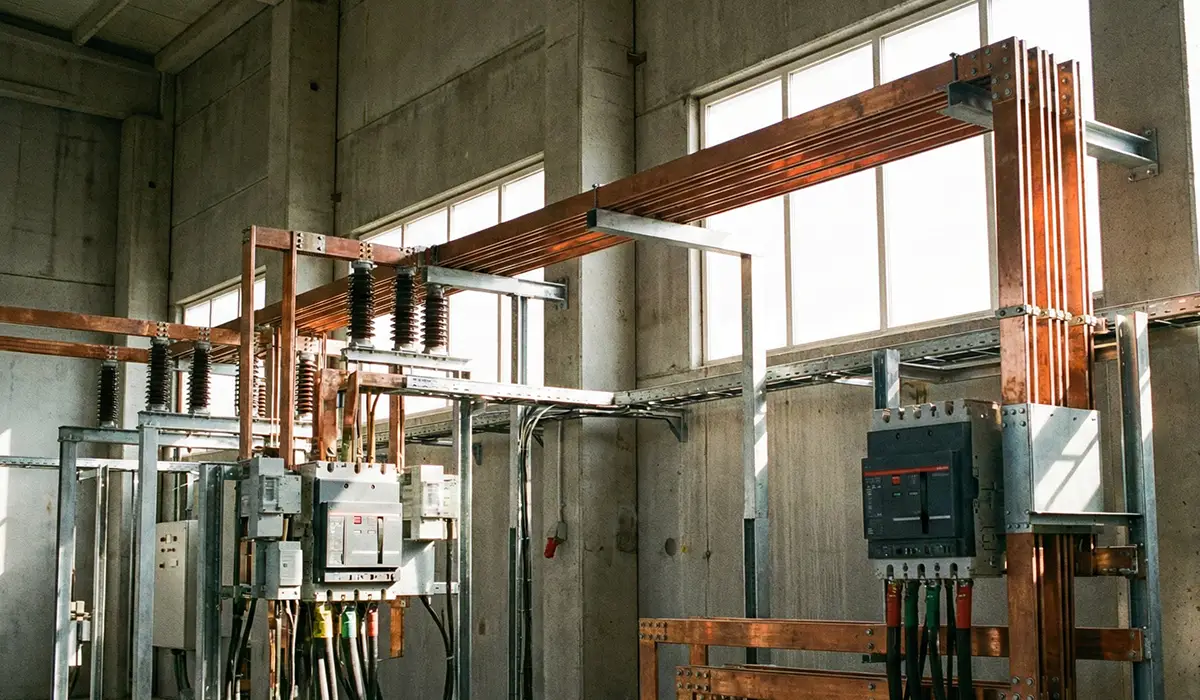
A busbar in electrical systems is a metallic conductor — typically a copper or aluminum strip, bar, or rod — that acts as a common junction where incoming electrical current is collected and then redistributed to multiple outgoing circuits. In simple terms, a busbar is the central highway of an electrical power distribution network, replacing dozens of individual cables with one rigid, low-resistance conductor.
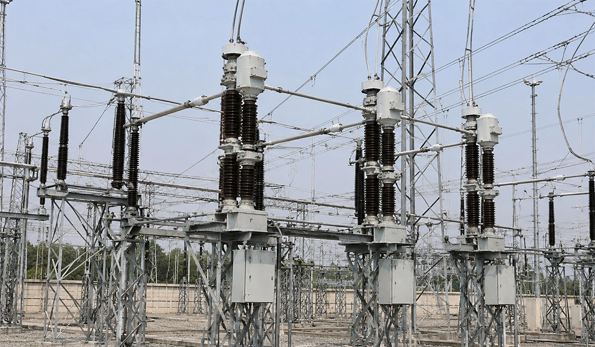
You’ll find busbars housed inside switchgear, panel boards, transformers, and substations, handling everything from low-voltage applications (up to 400V) to high-voltage transmission systems (765kV and beyond). Because they offer a large surface area, busbars dissipate heat efficiently, carry massive currents with minimal voltage drop, and simplify the layout of complex electrical assemblies.
The role of a busbar in electrical distribution boils down to three core functions:
- Current collection — gathering electrical power from incoming feeders (generators, transformers).
- Current distribution — channeling that power to outgoing circuits (loads, feeders, breakers).
- System organization — providing a clean, maintainable junction point that improves both safety and reliability.
For a broader view of how busbars fit into power distribution systems across different facility types, this pillar guide on electrical busbars for power distribution systems covers the full picture.
Once the role of the busbar itself is clear, the next critical design decision is choosing the right busbar arrangement — the configuration that determines how reliable, flexible, and cost-effective your power system will be.
If the details you gathered about Busbar in Electrical Systems were interesting and insightful, you may find diving deeper into busbar fabrication machine equally captivating.
The 8 Main Types of Busbar Arrangements Used in Substations
The type of busbar arrangement chosen for a substation directly determines its reliability, operational flexibility, maintenance ease, and overall cost. Engineers select among eight standard busbar arrangements based on factors such as supply continuity requirements, fault tolerance, voltage level, and budget. Below is a complete breakdown of every major type of busbar arrangement — from the simplest single busbar scheme to advanced configurations used in high-voltage transmission substations.
Before comparing all eight arrangements in detail, it can help to see how single and double busbar schemes stack up against each other at a glance. This comparison is covered in this article on single busbar and double busbar schemes.
1. Single Busbar Arrangement (Simplest & Most Cost-Effective Scheme)
The single busbar arrangement is the simplest, cheapest, and most widely used busbar configuration in low-voltage and small-substation applications. In a single busbar arrangement, all generators, transformers, and outgoing feeders connect to one common set of busbars, with each circuit controlled by its own circuit breaker and isolator.
Key advantages of the single busbar arrangement:
- Lowest installation and maintenance cost
- Simple operation and easy fault tracing
- Ideal for small substations, switchboards, and DC stations
Key disadvantages:
- A fault on the busbar shuts down the entire system
- Maintenance requires a full supply interruption
- Offers the lowest flexibility among all types of busbar arrangements
This single busbar scheme is preferred where continuity of supply is not critical and capital cost is the deciding factor.
For readers who want a foundational understanding of busbars before going further into arrangement types, this introductory article on what is a busbar is a good starting point.
2. Single Busbar Arrangement with Bus Sectionalization
The sectionalized single busbar arrangement improves on the basic single busbar scheme by splitting the bus into two or three sections using a sectionalizing circuit breaker and isolators. This allows engineers to isolate a faulty section without shutting down the entire substation — a major reliability upgrade at only marginally higher cost.
Why use a sectionalized single busbar arrangement:
- A fault in one section is isolated, keeping other sections live
- Each section can be independently shut down for maintenance
- Adding a current-limiting reactor between sections reduces fault MVA, allowing lower-rated circuit breakers
This busbar arrangement is the go-to choice for medium-sized substations and large generating stations where the budget doesn’t justify a full double busbar setup but supply continuity still matters.
Sectionalized arrangements like this one are also common in LV switchgear panels, where bus sections allow part of a panel to be isolated for maintenance. This concept is explored further in this article on busbar for LV panels.
3. Main and Transfer Busbar Arrangement
The main and transfer busbar arrangement uses two busbars — a main busbar carrying normal load, and a transfer (auxiliary) busbar that acts as a backup. A bus coupler with a circuit breaker and isolating switches allows engineers to shift any feeder from the main bus to the transfer bus without interrupting service.
Why this busbar arrangement is valuable:
- Any circuit breaker can be maintained without shutting down its feeder
- The transfer bus provides a backup path during faults
- Bus potential can be used to operate protection relays
- Achieves much higher continuity than a sectionalized single bus, at moderate cost
This type of busbar arrangement is widely deployed in interconnected power networks where periodic circuit-breaker maintenance must happen without disrupting supply to consumers.
Arrangements like this one are part of a larger family of distribution board configurations used across different facilities. For a broader look at how these boards are categorized, see this article on types of electrical power distribution boards.
Double Busbar Double Breaker Arrangement (Highest Reliability)
The double busbar double breaker arrangement is the most reliable — and most expensive — busbar configuration used in critical power systems. Each circuit is connected to two parallel busbars through two dedicated circuit breakers, meaning any feeder can draw power from either bus, and any single component can fail without dropping the load.
Why engineers choose double bus double breaker:
- Uninterrupted supply even during bus faults or breaker maintenance
- Maximum operational flexibility for switching circuits between buses
- Mandatory for nuclear plants, EHV grid stations, and mission-critical industrial loads
The trade-off is cost: double the breakers, double the busbars, and double the switchgear footprint. For utilities where downtime is unacceptable, this busbar arrangement is the gold standard.
Because every busbar in this configuration must withstand the full fault current of the system, mechanical strength under short-circuit conditions becomes a critical design factor. This is covered in detail in this article on busbar short-circuit withstand and mechanical strength.
5. Sectionalized Double Busbar Arrangement
The sectionalized double busbar arrangement combines the redundancy of a double busbar with the fault isolation of sectionalization. The main busbars are divided into independently switchable sections, while an auxiliary busbar provides a transfer path during maintenance. Any section can be removed from service and reconnected through the auxiliary bus without affecting other parts of the system.
Benefits of this busbar arrangement:
- Faults are localized to a single section instead of the full bus
- Maintenance on one section doesn’t impact the rest of the substation
- Higher fault tolerance than a plain double busbar setup
Because sectionalizing the auxiliary bus would inflate costs without adding meaningful reliability, only the main buses are typically sectionalized. This makes the arrangement a popular compromise in 110–220 kV substations where flexibility matters but budget constrains a full double-breaker scheme.
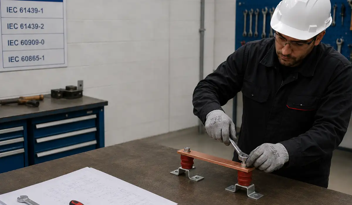
Arrangements at this scale must also comply with recognized international standards covering busbar design and verification. For an overview of the relevant requirements, see this article on busbar standards.
6. One-and-a-Half Breaker Busbar Arrangement
The one-and-a-half breaker busbar arrangement is the preferred scheme for large high-voltage and EHV substations because it delivers near-double-breaker reliability at significantly lower cost. As the name suggests, three circuit breakers are installed for every two circuits — meaning each circuit effectively shares one and a half breakers.
Why one-and-a-half breaker dominates HV substations:
- A bus fault or breaker failure never disconnects more than one circuit
- Additional circuits can be added without major reconfiguration
- Protection relays use bus potential, simplifying coordination
- 33% fewer breakers than a full double-bus double-breaker scheme
This busbar arrangement is the standard in 400 kV and 765 kV transmission substations worldwide where reliability is critical but full double-breaker cost cannot be justified.
At this scale, correctly sizing every busbar segment for its continuous and fault current becomes essential to the overall design. The methodology behind this process is covered in this article on busbar sizing.
7. Ring Main Busbar Arrangement
The ring main busbar arrangement connects the end of the busbar back to its starting point, forming a closed loop. Every feeder is supplied through two paths around the ring, meaning a fault on any single section can be isolated without interrupting any consumer.
Advantages of the ring main busbar arrangement:
- Two independent supply paths for every load
- Circuit breakers can be maintained one at a time without disrupting service
- Fewer breakers needed than double-bus schemes
Disadvantages:
- If one breaker is opened, the ring becomes radial and overloads can occur
- Difficult to expand — adding new circuits requires opening and reconfiguring the loop
- Protection coordination is more complex
Ring busbar arrangements are common in medium-voltage industrial distribution and in transmission substations with a limited and stable number of circuits.
In ring main configurations, the connection points between busbar sections and feeder terminals are just as important as the bars themselves. For more on these connection components, see this article on terminal bus bar.
8. Mesh Busbar Arrangement
The mesh busbar arrangement uses four circuit breakers arranged in a mesh, with each circuit connected at a node of the mesh. When a fault occurs, only two adjacent breakers open, isolating the fault while keeping the rest of the substation energized.
Key features of the mesh busbar arrangement:
- Excellent protection against busbar faults
- Each circuit is fed from two directions, similar to a ring scheme
- Lower breaker count than one-and-a-half breaker arrangements
Limitations:
- Limited switching flexibility compared to double-bus schemes
- Not easily extendable beyond the original mesh design
- Best suited to substations with a fixed circuit count
The mesh busbar arrangement is most commonly found in EHV substations handling a stable number of high-power circuits.
Designing the physical layout of a mesh arrangement often involves software tools that model busbar geometry, clearances, and fault forces. These tools are discussed in this article on busbar design software.
Type of Busbar Arrangement Comparison: Which One Should You Choose?
Choosing between the different types of busbar arrangements comes down to balancing four factors: reliability, flexibility, cost, and ease of maintenance. The table below summarizes the trade-offs across all eight types of busbar arrangements:
| Type of Busbar Arrangement | Reliability | Cost | Typical Application |
|---|---|---|---|
| Single Busbar | Low | Lowest | Small substations, LV systems |
| Sectionalized Single Busbar | Medium | Low | Medium substations |
| Main & Transfer Busbar | Medium-High | Moderate | Interconnected MV networks |
| Double Busbar Double Breaker | Highest | Highest | Nuclear, EHV critical loads |
| Sectionalized Double Busbar | High | High | 110–220 kV substations |
| One-and-a-Half Breaker | Very High | High | 400 kV+ transmission |
| Ring Main | High | Moderate | MV industrial, stable substations |
| Mesh | High | Moderate-High | EHV with fixed circuits |
For small applications where cost rules, the single busbar arrangement wins. For mission-critical power systems, the double busbar double breaker or one-and-a-half breaker arrangement is the right type of busbar to specify.
Once an arrangement type is chosen, the next step is selecting the right busbar specification for the panel itself. This selection process is covered in this article on busbar selection guide for LV panels.
Conclusion Types of Busbar Arrangements
Busbars are essential components in electrical distribution systems, ensuring efficient and reliable power transmission. Understanding the different types of busbar arrangements and the advanced machinery used in their processing is crucial for designing robust and efficient electrical systems. From busbar bending machines and busbar bender machines to sheet metal punch machines and automatic punching machines, the right equipment can significantly enhance the performance and reliability of busbar systems. By investing in high-quality busbar machines from manufacturers like PAYAPRESS and understanding their capabilities, businesses can optimize their operations and ensure the safe and efficient distribution of electrical power.