









What Is a Ground Bus Bar?
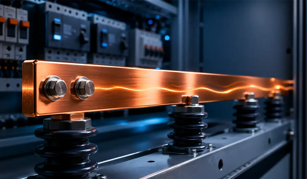
A ground bus bar is a flat copper or aluminium strip mounted inside an electrical enclosure and bonded directly to it. Unlike the busbars that distribute power in the same enclosure, it carries no current in normal operation. It collects the equipment grounding conductors from circuit breakers, enclosures, equipment chassis and infrastructure, and gives them one common connection point.
Physically it is a drilled or tapped bar with a row of terminations. Tinned copper is common where corrosion is a concern, because the plating resists the oxide film that raises contact resistance over time. Whatever the finish, the bar must be solidly bonded to the enclosure — that bond is what makes the enclosure itself part of the grounding path.
Beyond terminating conductors, the bar creates an equipotential plane. When every metal frame in an installation is tied to a common reference, the voltage difference between any two surfaces stays near zero. That matters for shock safety and, in telecom and industrial environments, for keeping noise off sensitive electronics.
What Happens During a Fault
Follow the current, because this is where most explanations go wrong.
A live conductor touches a metal enclosure. Current flows through the enclosure, into the ground bus bar, along the equipment grounding conductor, back to the supply panel, and through the main bonding jumper onto the neutral — which returns it to the source transformer winding. That loop has low impedance, so fault current is high, so the breaker trips in milliseconds.
The grounding electrode — the rod or plate in the soil — plays no part in that loop. Typical soil resistance is 5 to 25 ohms. At 120 V, 25 ohms passes under 5 amps. That will not trip a 20 A breaker, and the faulted enclosure stays live at close to full voltage.
The electrode system does two other jobs: it references the system voltage to earth, and it gives lightning and utility surges a path away from the building. Both matter. Neither is fault clearing.
The practical consequence: the integrity of the bond from bar to enclosure, and of the EGC back to the source, is what keeps people alive. A perfect ground rod does not compensate for a loose bonding screw.
Ground Bus Bar, Grounding Busbar, Ground Bar: What to Call It
The same component goes by several names, and the inconsistency causes real confusion in specifications and RFQs.
Ground bus bar, ground busbar, grounding bus bar, grounding busbar, ground bar, grounding bar — these all mean the same thing. There is no technical distinction. “Bus bar” as two words is the older convention and still dominant in North American code language; “busbar” as one word is standard in IEC documents and in the manufacturing trade. NEC Article 250 uses “busbar”.
Two terms are distinct and should not be used loosely:
- Neutral bar (grounded conductor terminal bar) carries return current during normal operation. Different function, different mounting rules.
- TGB and TMGB are specific telecom bars defined by TIA-607-D with defined dimensions and hole patterns. Not every ground bar is a TGB.
One more that trips people up: “busbar grounding” usually means something else entirely — the earthing of a distribution busbar system or busway, rather than the ground bar itself. If a supplier quotes for “busbar grounding” when you asked for a ground bus bar, confirm which one they mean before the order goes out.
Codes and Standards: NEC, UL, TIA and IEC
Four regimes govern ground bus bars, depending on where the assembly is sold and what it is part of. This section covers each in turn. For the wider set of busbar standards that apply to distribution conductors rather than grounding, see our standards overview.
NEC Article 250 and Article 408
Article 250 is the grounding and bonding backbone in the US. It defines the grounding electrode conductor, the equipment grounding conductors, and how they tie together. Two provisions matter most for the bar itself:
- 250.8 limits how grounding conductors may be connected. Sheet metal screws are not permitted. Connections must use listed pressure connectors, listed clamps, exothermic welding, or machine screws engaging at least two threads or secured with a nut.
- 250.24(A)(5) and 250.142 together produce the rule everyone knows: neutral and ground bond at the service disconnect and nowhere downstream.
Article 408 covers the panelboard. 408.40 requires that equipment grounding conductors terminate on a grounding bar bonded to the panelboard cabinet — and that where an isolated ground is used, the isolated bar is insulated from the enclosure per 250.146(D).
UL 467 and CSA C22.2 No. 41
UL 467 is the North American listing standard for grounding and bonding equipment, and it is what an inspector looks for on the bar. CSA C22.2 No. 41 is the Canadian equivalent; NMX-J-590-ANCE may apply in Mexico.
The listing covers the bar together with its hardware. Substituting your own screws or lugs for the ones supplied can void it — a common finding on inspection.
TIA-607-D: TGB and TMGB
Telecom spaces use bars defined by TIA-607-D, and unlike general ground bars these have specified dimensions.
The TMGB (Telecommunications Main Grounding Busbar) sits in the entrance facility or main telecom room and is the single connection point between the building’s grounding electrode system and the whole telecom bonding infrastructure. Minimum cross-section is 6 mm × 50 mm — roughly ¼ in × 2 in — in copper. Commercially, ¼ in × 4 in is the common TMGB size.
The TGB (Telecommunications Grounding Busbar) serves an individual telecom or equipment room, at the same 6 mm × 50 mm minimum. Typical stocked sizes are ¼ in × 2 in × 6, 10 or 12 in.
The TBB (Telecommunications Bonding Backbone) links each TGB to the TMGB in a star topology. Minimum size is 6 AWG copper, sized at 2 kcmil per linear foot of run, up to a 750 kcmil maximum.
Two details that are easy to miss:
- Hole patterns accept two-hole compression lugs — typically 5/16 in holes on 5/8 in centres, or 7/16 in holes on 1 in centres.
- Connector surfaces must have an electrochemical potential below 300 mV relative to the busbar, to prevent galvanic corrosion at the joint.
IEC 61439
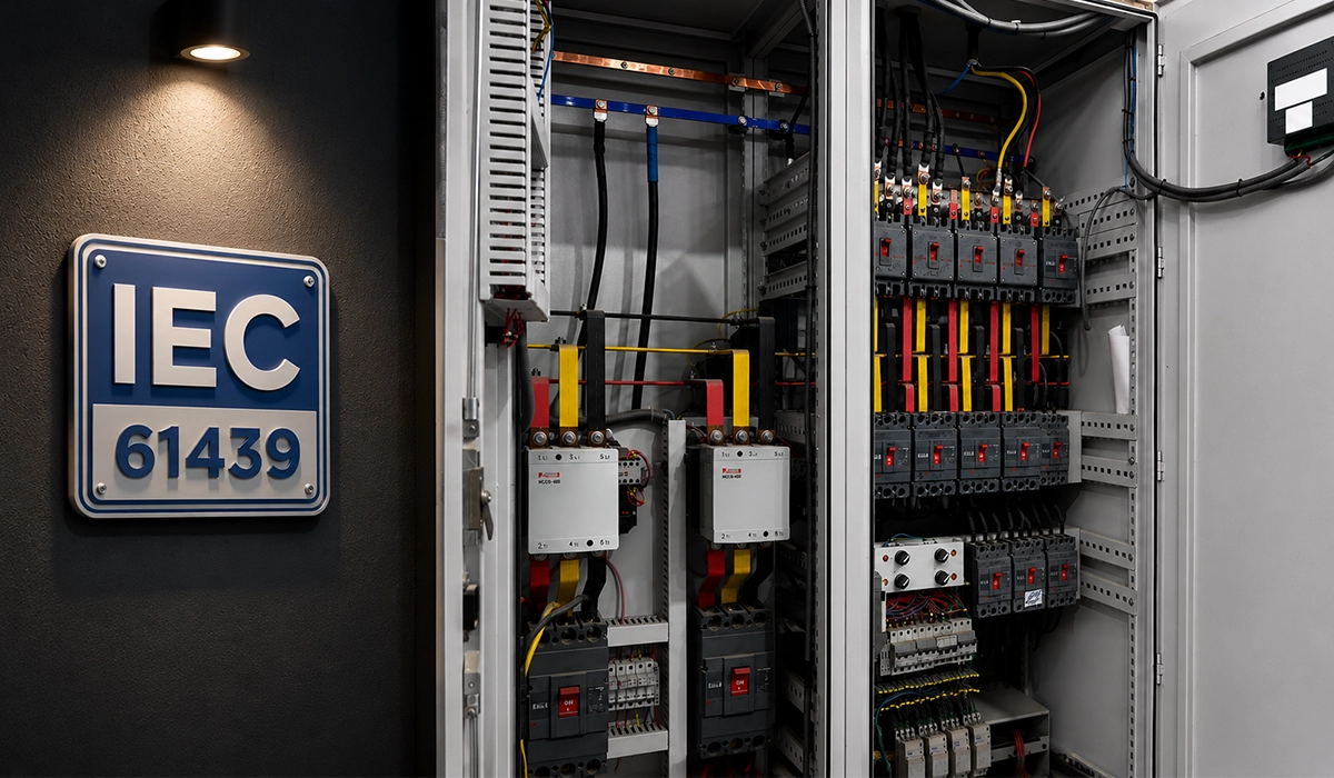
For low-voltage assemblies outside North America, IEC 61439 governs. It does not prescribe a ground bar size directly, but it sets the verification framework — the protective circuit continuity and short-circuit withstand of the assembly must be verified by test or by comparison with a tested reference design. For panel builders producing UL and CE dual-certified equipment, the practical effect is that the grounding arrangement must satisfy both regimes, which usually means designing to whichever is stricter.
Ground Bus Bar in an Electrical Panel
Where the bar goes and how it is bonded depends entirely on whether the panel is service equipment or a subpanel. Get this wrong and the installation is unsafe even though every connection looks tidy.
This section covers the grounding bar specifically. For the phase and neutral bars that carry load current in the same enclosure, see what a busbar does in an electrical panel.
Main Panel (Service Equipment)
At the service disconnect, neutral and ground are bonded. The main bonding jumper — usually a green screw or strap supplied with the panel — connects the neutral bar to the enclosure. This is the point where fault current transfers from the grounding system to the neutral to return to the transformer. It is the one place the bond is required.
The grounding electrode conductor also lands here.
Subpanel
In a subpanel, neutral and ground must be separated:
- The neutral bar is mounted on insulating standoffs, isolated from the enclosure.
- The ground bar is bonded solidly to the enclosure.
- The main bonding jumper is removed or left uninstalled.
- The feeder must include four conductors — two hot, one neutral, one EGC.
If neutral and ground are bonded in a subpanel, normal load current divides between the neutral conductor and the metal path — conduit, enclosures, equipment frames. Those parts become current-carrying under normal operation. The result is nuisance GFCI tripping at best, and an energised enclosure at worst.
This is the single most common fault found when adding a ground bar to an existing subpanel: the panel was originally wired with three conductors and the neutral bonded, and simply adding a ground bar without pulling a fourth conductor does not fix it.
Adding a Bar to an Existing Panel
- Use the panel manufacturer’s bar where one exists. Its mounting holes align with the tapped holes already in the enclosure, and the combination is listed.
- Panel mounting holes are usually pre-tapped, with the threads hidden under paint. Drilling fresh holes should be a last resort.
- Do not repurpose a neutral bar as a ground bar by removing its bonding jumper. On most panelboards this violates the listing, because the bar was evaluated as part of the neutral assembly.
- Scrape or otherwise break the paint at the mounting face if the bar seats on a painted surface. Paint is an insulator, and the bond is the whole point.
Ground Bar vs Neutral Bar: The Difference That Matters
| Ground Bus Bar | Neutral Bar | |
|---|---|---|
| Carries current | Only during a fault | Continuously, under normal load |
| Mounting in a subpanel | Bonded to enclosure | Isolated on standoffs |
| Mounting in service equipment | Bonded to enclosure | Bonded via main bonding jumper |
| Conductor colour | Green, green/yellow, or bare | White or grey |
| Double-lugging | Not permitted unless listed for it | Not permitted |
The functional distinction is simple: a neutral is a current-carrying conductor; an EGC is not, except for the fraction of a second during a fault. Everything else follows from that.
A common field example: a subpanel is installed in a renovated office floor with the neutral and ground tied to a single bar. Under normal load, return current now has two paths — the neutral conductor and the metal enclosure — and divides between them. Nothing appears wrong until a GFCI-protected circuit starts tripping without an obvious cause, because the device sees an imbalance that is not a fault. The fix is to isolate the neutral bar, land the EGCs on a separate bonded ground bar, and confirm the feeder actually contains four conductors. If it does not, the feeder has to be replaced — there is no shortcut.
Materials and Plating
Copper is the default. High conductivity, ductile enough to bend without cracking, and it takes a mechanical termination reliably.
Tinned copper is copper with a thin electroplated tin layer. The tin does not meaningfully change conductivity — it protects the joint. Bare copper forms an oxide film that raises contact resistance over time; higher resistance means more heat at the joint, which accelerates the oxidation. Tin plating interrupts that cycle. Specify it for coastal, humid, chemically aggressive or outdoor-rated enclosures.
Aluminium costs less and weighs about a third of copper, but carries roughly 60% of the conductivity for a given cross-section, so the bar must be larger for the same duty. The real issue is the joint: aluminium forms an insulating oxide within seconds of exposure to air, and it creeps under sustained clamping pressure, so a joint torqued correctly on day one loosens over time. Aluminium ground bars need an antioxidant compound, wire brushing at the joint face, Belleville washers, and re-torquing after the first thermal cycles. Where an installation is unlikely to get that attention, copper is the safer specification.
Plating alternatives: nickel plating suits higher operating temperatures and harsher atmospheres than tin; silver gives the lowest contact resistance but is rarely justified on a grounding bar, where the duty is intermittent.
Ground bars for high-current panels are cut, punched and shaped on busbar processing equipment so hole positions and edge quality stay consistent — a burred or off-position hole compromises the very contact area the bar depends on.
| Type | Typical Use | Watch Out For |
|---|---|---|
| Copper | Standard indoor panels and switchgear | Oxide film at joints over time |
| Tinned copper | Coastal, humid, corrosive, outdoor enclosures | Slightly higher cost; no conductivity penalty |
| Aluminium | Cost- and weight-sensitive installations | Creep and oxide; needs antioxidant and re-torque |
| TGB / TMGB | Telecom rooms and entrance facilities | Must meet TIA-607-D dimensions and lug spacing |
| Rack ground bar | Server and network cabinets | Bonding path from rack back to the TGB |
| Isolated ground bar | Sensitive electronics, per NEC 250.146(D) | Insulated from enclosure — different rules apply |
Ground Bus Bar Sizing
Ground bus bar sizing is three separate questions, and mixing them up is where specifications go wrong:
- What size are the conductors landing on the bar?
- What cross-section does the bar itself need?
- How many terminations must it accept?
Take them in that order.
1. Sizing the Conductors (NEC Table 250.122)
Equipment grounding conductors are sized from the rating of the overcurrent device protecting the circuit — not from the load, and not from the phase conductor ampacity. NEC Table 250.122 gives the minimum:
| OCPD Rating | Copper EGC | Aluminium EGC |
|---|---|---|
| 15 A | 14 AWG | 12 AWG |
| 20 A | 12 AWG | 10 AWG |
| 60 A | 10 AWG | 8 AWG |
| 100 A | 8 AWG | 6 AWG |
| 200 A | 6 AWG | 4 AWG |
| 300 A | 4 AWG | 2 AWG |
(Abbreviated. Consult the current NEC edition for the full table.)
Three rules that catch people out:
- Round up, never down. For a 250 A device, 250 A is not a table row — go to the next entry (300 A) and use 4 AWG copper.
- Upsized phase conductors mean an upsized EGC. If you increase the ungrounded conductors for voltage drop, NEC 250.122(B) requires the EGC to increase proportionally by circular mil area.
- The EGC never needs to be larger than the phase conductors it runs with.
Where several circuits share a raceway, one EGC sized for the largest overcurrent device serves them all.
2. Sizing the Bar Itself
For a panelboard ground bar, the bar rarely governs — a standard listed bar comfortably carries the fault current the terminations can deliver. Two cases where you must check:
The bonding jumper rule. The connection from the bar to the enclosure must be not smaller than the largest equipment grounding conductor landing on it. This is the most frequently missed sizing requirement, because people size the bar and forget the bond.
Switchgear and high-fault-current assemblies. Here the bar is sized thermally rather than by termination count, using the same adiabatic method covered in our guide to busbar sizing by current and temperature rise — the bar must absorb the fault energy without exceeding its temperature limit before the protection clears:
A = (I × √t) / k
where A is cross-sectional area in mm², I is fault current in amps, t is clearing time in seconds, and k is a material constant.
The value of k is not universal — it depends on the standard applied and on the assumed initial and final temperatures. IEEE 80 and IEC 60949 use different constants for the same copper. Always take k from the standard your assembly is verified to, and state the assumed clearing time on the drawing. As a reference point, IEC 60298 sets a 50 mm² minimum copper cross-section for ground bars in metal-enclosed switchgear rated 1 to 52 kV.
3. Sizing by Termination Count
Often the real constraint. Work through:
- Count every EGC that will land, then add spare capacity — 25% is a reasonable allowance for future circuits.
- One conductor per hole. Double-lugging is a code violation unless the bar is specifically listed for two conductors under one screw, and most are not.
- Check the hole size range. A bar with uniform small holes cannot accept a large feeder EGC. Choose a bar with a mixed hole map if the panel has both branch circuits and a large feeder.
- Leave torque access. Holes crowded to the end of a bar make it impossible to get a torque driver square on the screw, which is how under-torqued connections happen.
Selection Checklist
Once sizing is settled, confirm:
- Listing — UL 467 for North America, CSA C22.2 No. 41 for Canada
- Environment — tin-plated for humid, coastal or corrosive locations
- Hole pattern — two-hole lug spacing if the bar serves telecom or racks
- Panel compatibility — mounting holes matching the panelboard’s tapped holes, and a bar listed by the panel manufacturer where possible
- Accessories — insulators, standoffs, covers and identification labels
Grounding Busbar Installation: Step by Step
1. De-energise and verify. Lock out the supply and test that the panel is dead before opening it. Test the tester first.
2. Prepare the mounting face. Locate the panel’s pre-tapped mounting holes. Where the bar seats on painted metal, remove the paint at the contact area — paint is an insulator and will compromise the bond.
3. Mount the bar. Use the hardware supplied with the listed bar. In a subpanel, confirm the bar seats directly against the enclosure metal; in the neutral position, confirm the insulating standoffs are in place.
4. Verify the bond. Measure resistance between the bar and a clean point on the enclosure. It should be essentially zero — a fraction of an ohm. Anything higher means paint, a burr, or a loose screw.
5. Land the conductors. One per hole. Strip to the correct length so no bare conductor extends past the termination and no insulation is trapped under the screw.
6. Torque to specification. Follow the manufacturer’s figure with a calibrated torque driver. Under-torqued connections develop resistance, heat, and eventually fail; over-torqued connections deform the conductor and fail the same way. NEC 110.14(D) requires torque values to be applied where the equipment is marked with them.
7. Route conductors short and direct. Long looping EGCs add impedance to the fault path. Route them along the shortest practical route to the bar.
8. Label and document. Mark each termination so the next technician knows what lands where.
9. Re-torque after commissioning. On aluminium conductors especially, re-check torque after the first load cycles.
Common Installation Mistakes
- Double-lugging conductors under one screw on a bar not listed for it
- Landing a neutral on the ground bar in a subpanel
- Mounting through paint without preparing the surface
- Sheet metal screws used for a grounding connection — prohibited by NEC 250.8
- Missing bonding jumpers between enclosures in multi-cabinet assemblies
- Substituted hardware that voids the UL 467 listing
- Overcrowded bars that leave no room for a torque driver
Applications and Environments
Data centres. Horizontal and vertical rack ground bars keep equipment grounds short and consistent, and bond back to the room’s TGB. Short is the operative word — impedance rises with length, and at the frequencies of switching noise it rises faster than DC resistance suggests.
Telecom rooms. TGB and TMGB bars per TIA-607-D provide the structured bonding point for racks, cable shields and surge protectors, with the whole set tied back through the bonding backbone.
Wireless and tower sites. Two-hole lug patterns integrate lightning protection, coax shield grounding and equipment bonding at a common bar. Here the electrode system genuinely does matter, because lightning energy is dissipated to earth rather than returned to a source.
Marine and vehicle DC systems. A negative bus serves as the common reference alongside chassis bonding. Note the difference from AC practice: there is no neutral, and the negative bus is a current-carrying conductor, so the AC rules about separating ground from neutral do not translate directly.
Industrial switchgear. IEC assemblies incorporate the grounding bar into the verified assembly, with protective circuit continuity confirmed as part of type testing.
Each environment sets its own priority — corrosion resistance offshore, mechanical robustness in industrial plant, termination density in data halls.
Procurement Guide: What Spec Sheets Should Include
When ordering ground bus bars or preparing RFQs, make sure the specification covers material and finish (copper, tinned copper, aluminum), dimensions and thickness, hole map (spacing, sizes, counts, thread sizes), included hardware (insulators, brackets, lugs), listings (UL 467 marking, TIA-607-D compliance), and documentation (installation instructions, torque tables, warranty). A clear spec sheet keeps manufacturing and field teams aligned and simplifies inspection.
Conclusion
A ground bus bar isn’t just another metal strip in a panel; it’s a central piece of your grounding and bonding strategy that impacts safety, compliance, and system stability. Whether you’re specifying one based on NEC grounding and bonding rules, or selecting a telecom grounding busbar (TGB/TMGB) with pre-drilled two-hole lugs, grounding deserves thoughtful attention.
Choosing the right material — often copper or tin-plated copper for corrosive environments — and verifying UL 467 listing and relevant telecom standards like TIA-607-D helps ensure both inspectors and installers are satisfied. Good sizing and spacing guided by code and real-world conditions reduces impedance and promotes an equipotential plane, keeping fault currents under control. With a clear checklist and understanding of how ground bus bars fit into NEC, UL, and industry practices, panel builders, specifiers, and field technicians can all work from the same reliable foundation.




Rate this article
Choose a rating from 1 to 5 stars.
No ratings yet