



If you’d rather listen than read, feel free to play the audio file below for the rest of this article.
Generation to Grid: The Electrical Path
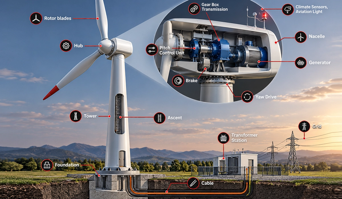
How does electricity get from a wind turbine nacelle to the grid? First, the generator makes low-voltage AC. Next, a converter conditions it and a transformer steps it up. Then collector cables join each turbine to a substation. Good wind farm electrical design keeps this path short, cool and easy to isolate. Every part of the wind turbine electrical system must also cope with wind-driven load swings.
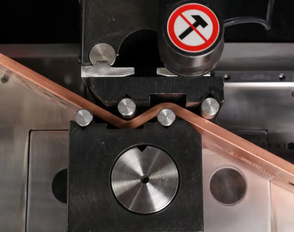
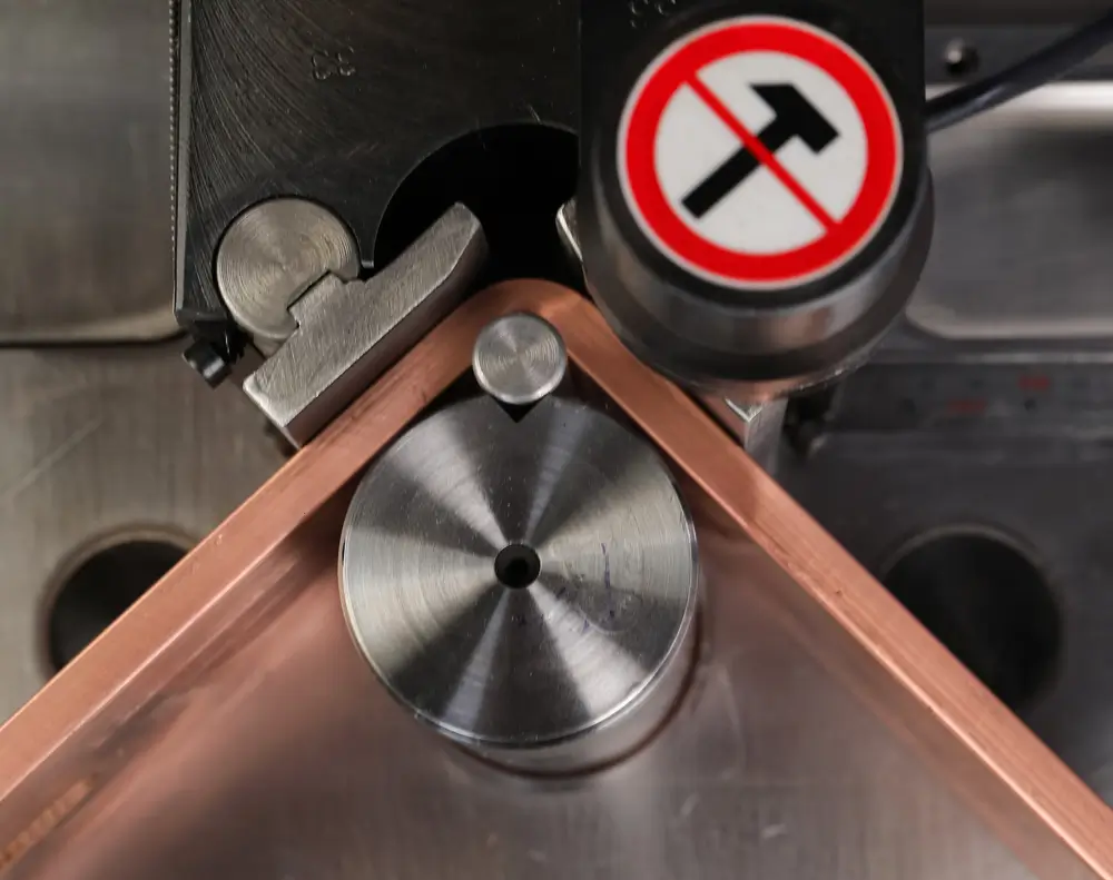
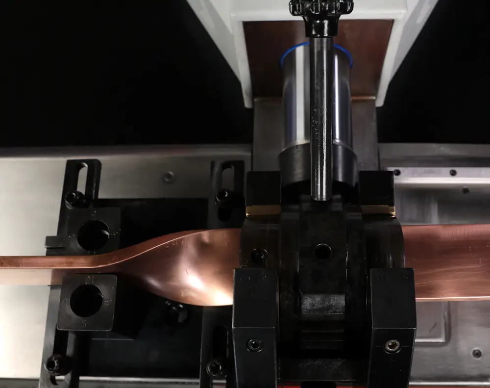
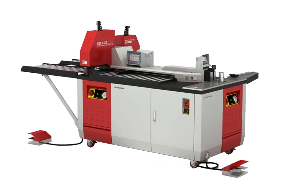
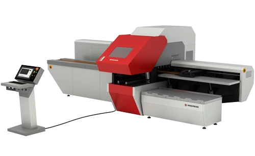
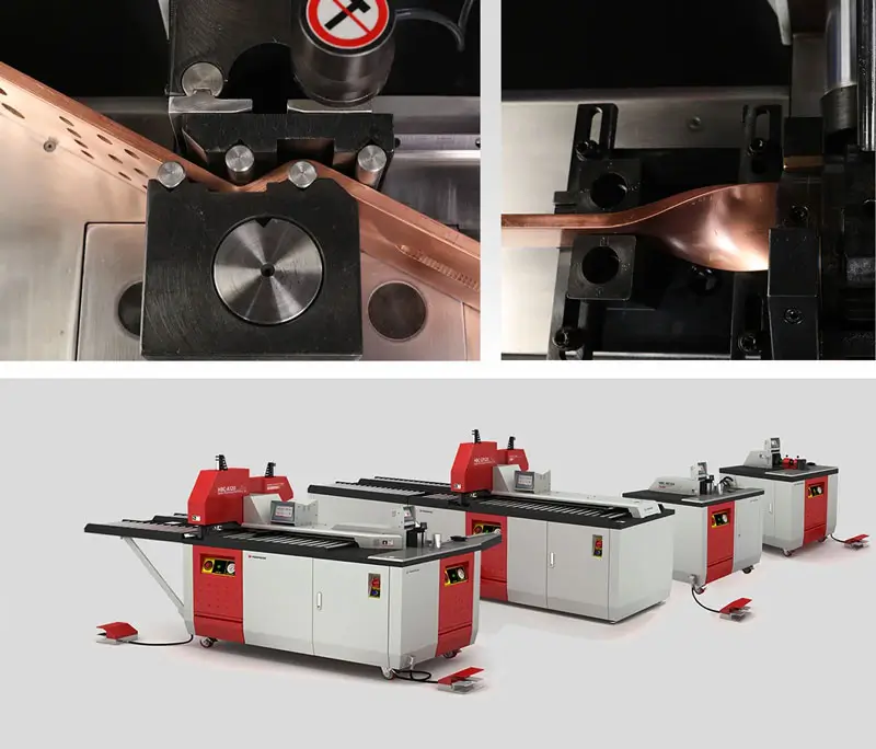
The HBC-CP160 machine is designed for accurate fabrication of copper and aluminum busbars up to 160 × 15 mm. Its independent hydraulic stations enable simultaneous operations, making it suitable for repetitive switchgear manufacturing tasks.
Generator and Converter
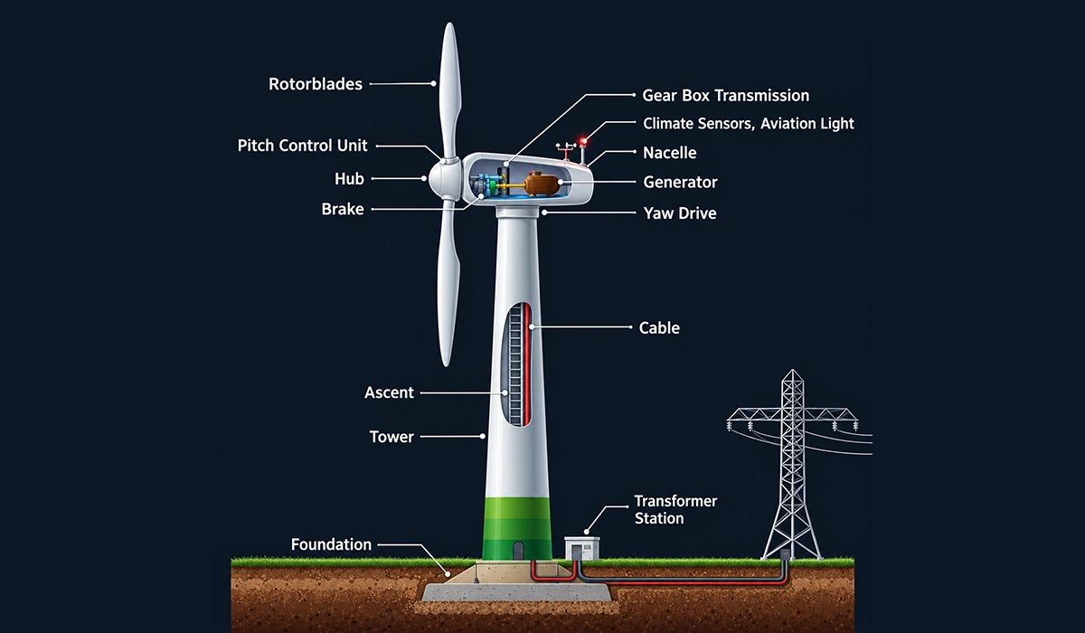
The nacelle is the housing on top of the tower. Inside it, the generator turns rotor motion into three-phase AC power. However, its voltage and frequency change with wind speed, so the grid cannot accept it directly. A wind turbine converter fixes this. Its job is to match the generator to the grid, whatever the wind does. First, it rectifies the AC to DC. Then it inverts the DC back to AC at grid frequency. In the nacelle electrical system, the converter sits close to the generator to keep cables short. Generation voltage is typically around 690 V, so a step-up stage must follow. Converters also lose some energy as heat, so cooling shapes the cabinet layout.
Every conductor along this path must carry high current safely and stay easy to service. Our guide to electrical busbars explains how these power distribution systems are built and applied.
DFIG vs Full Converter Systems
Two layouts dominate. A doubly fed induction generator (DFIG) connects its stator straight to the grid through the transformer. Its rotor connects through a converter that handles only part of the power. In contrast, a full-converter design sends all power through the converter. This DFIG vs full converter wind turbine choice has clear trade-offs. A DFIG uses a smaller converter, so it usually costs less. A full converter allows a wider speed range and gentler grid support, but it needs a larger converter and more cooling.
For example, a DFIG feeds the grid through two paths, while a full converter feeds it through one. Rotor and stator currents also differ between the two layouts, so busbar and cable sizing must follow the chosen topology. Therefore, ask each supplier for the single-line diagram early. Neither layout wins everywhere. Site rules, grid codes and supplier experience decide.
Down-Tower Power Transmission: Cable vs Busbar
Down-tower power transmission moves the full turbine output from the nacelle to the tower base. Most turbines use cables for this run. Some designs use busbars instead. So, do wind turbines use busbars? Yes, in some designs, and the choice depends on tower movement, installation time and cost. Each option also shapes the tower interior, the supports and the erection schedule, so this section compares the two on those terms.
Tower busbar layouts are easier to judge when you can read how designers segment them. A published patent describes pre-installed busbar elements with clamping holders in its segmented busbar patent.
Limits of Cable Runs
Cables remain the default, yet they have limits. One patent notes that crews usually pull cables into the tower after erection, which is slow and costly. Another describes stiff cables that are hard to lay in cold weather.
Tower movement adds stress. A third patent reports relative movement of up to about 100 mm over a 6 m tower section, which has broken cable tray supports. Long cable bundles also take space and need bending radius, which competes with ladders, lifts and platforms inside the tower. As a result, designers look for supports and conductors that tolerate this motion. Cable still works well when the supports are right. These issues push some teams to test alternatives.
Tower Busbar Systems
A tower busbar system replaces the cable bundle with bars fixed along the tower wall. One vendor, Conductix-Wampfler, describes its aluminium Tower Buss as a cost-effective alternative to cables, with insulated bars that flex with the tower [Vendor claim]. Sections bolt together to form a continuous column. Patents describe similar bar modules that clamp together between tower sections.
However, an earlier patent argues that conventional rigid bus duct costs more than cable and needs magnetic shielding . Neither source gives independent test data, so treat both as design inputs, not proof. The busbar vs cable for wind turbine tower decision therefore needs project quotes, not slogans. Ask for short-circuit and vibration test reports before you commit. For example, aluminium bars weigh less than copper bars of equal rating, but they need a larger cross-section, so compare copper vs aluminium on weight, joint design and price.
Installing Busbars in Tower Sections
Busbars can go in before the tower reaches the site. A published patent describes bar elements pre-installed in each tower section and held by clamping holders at the lower end. On site, crews join neighbouring sections with connecting elements that bridge the flange. These flexible connector parts absorb small movement between sections. A protective casing can also shield climbers from live bars. This approach moves labour from the tower to the workshop, but it demands tight dimensional control. Check hole positions and bar ends against the drawing before shipping.
Tower movement makes joint design just as important as conductor choice. See our guide to flexible busbar types for sizing, standards and best uses.
Nacelle and Tower Electrics: Pitch, Yaw and Slip Rings
The nacelle holds more than the generator. Typical wind turbine electrical components there include the converter cabinet, the controller, auxiliary supplies, sensors and motor drives. What electrical components are in a nacelle depends on the design, so the single-line diagram is the best guide.
The pitch system turns each blade on its axis. It controls how much energy the blades capture, and it can feather the blades to slow the rotor in high wind. However, the pitch drives sit in the rotating hub, so they need power and signals from the fixed nacelle. A wind turbine slip ring provides that link by passing current between rotating and stationary parts.
Slip ring wear is a maintenance topic. One vendor claims that its gold-plated rings and brush arrangements last 100 million revolutions or more. Therefore, ask suppliers for test data, not only datasheet claims. Plan access so crews can replace worn parts quickly.
The yaw system turns the nacelle to face the wind. Its motors draw power through the same tower cables or busbars. As the nacelle rotates, the cables twist, so many designs limit the number of turns and then untwist the cable loop. The controller also commands the brake, which holds the rotor still for maintenance after the pitch system stops it.
Cooling and heating need power too. Fans, pumps and heaters keep the converter and generator within temperature limits, so they add to the nacelle load. Finally, a control network links all these parts, so route signal cables away from power conductors to limit interference.
Pitch, yaw and brake duties all draw power from the nacelle system, so their supply must stay reliable. The US Department of Energy describes each subsystem in its turbine component guide.
Compact power distribution along a fixed route keeps these loads organised and easy to isolate. Learn how busbar trunking delivers power to many loads from a single run.
Transformer and Medium-Voltage Switchgear
A step-up transformer raises the converter voltage to a medium voltage for the wind farm cables. Higher voltage means lower current, which cuts losses over long cable runs. In many turbines the wind turbine transformer sits at the tower base. The NREL study notes a typical step from 690 V to 25–40 kV, partly because larger transformers would not fit the tower cross-section.
Dry-type and liquid-filled units both appear in turbines. Liquid-filled units can be compact, whereas dry-type units cut fire load and leak risk. Offshore projects often use a biodegradable coolant. Therefore, match the transformer type to the site and the insurer’s rules.
Some designs place the transformer in the nacelle instead. However, that adds weight that the yaw system must carry.
Medium-voltage switchgear sits between the transformer and the collector cables. It switches, protects and isolates the turbine. Typical functions include load switching, earthing of de-energised cables and protection against overcurrent and earth faults. Insulation type affects size and service, so ask your supplier early. Collector voltages near 33 kV fall inside the 1 kV to 52 kV range of IEC 62271-200 for metal-enclosed assemblies. A ring main unit (RMU) is one compact form of such switchgear, and our ring main unit guide covers it in more detail.
The link between transformer and tower matters for busbars. Low-voltage runs from the converter carry high current, so cross-section and joint quality set the heat. In contrast, medium-voltage runs carry less current but need clearance and insulation. Therefore, size the tower base area for the transformer, the switchgear and safe access.
Switchgear must match the voltage class and the installation site, so the governing standard matters. The EVS catalogue entry lists the scope of EN IEC 62271-200 in its switchgear standard scope.
Inside the switchgear, busbars distribute power between the incoming and outgoing circuits. Read more about LV switchgear panels and the safety points that shape their design.
Designing for Vibration, Temperature and Corrosion
Tower motion, daily temperature swings and salt air attack every joint. Wind turbine busbar vibration resistance therefore starts with the support design, not the bar itself. Elastic bearings and flexible connectors let the bars move without cracking joints. A published patent, for example, fastens clamping brackets through elastic bearings .
Daily and seasonal swings change bar length, so expansion joints or flexible links must absorb the difference. Flexible connectors need fatigue checks. Laminated or braided copper links bend easily, but repeated motion can break strands, so inspect them on a schedule.
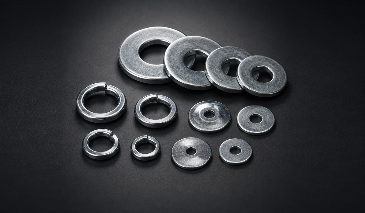
Bolted joints are the weak point to watch. Thermal cycling makes bars expand and contract, and vibration can loosen fasteners. As a result, joints need correct contact pressure, spring washers or similar load-keeping parts, and regular torque checks . Aluminium relaxes under sustained clamp load more than copper, so each metal needs its own joint detail.
Vibration and fault currents load the bars and their supports in different ways. Our article on mechanical strength explains how busbars withstand short-circuit forces.
Plating protects contact faces. Tin or silver plating on copper is common, and joining copper vs aluminium needs a compatible surface to avoid galvanic corrosion Offshore corrosion adds salt deposits and humidity. Therefore, rate the site first, then choose plating, coatings and enclosure details. Seal bolt heads and joints where moisture can collect, and keep dissimilar metals apart.
Vibration and fault currents load the bars and their supports in different ways. Our article on mechanical strength explains how busbars withstand short-circuit forces.
Offshore towers face salt-laden air, so designers need a recognised way to rate site corrosivity. ISO 12944-2 defines atmospheric corrosivity categories for steel structures in its corrosivity classification standard.
Vibration and fault currents load the bars and their supports in different ways. Our article on mechanical strength explains how busbars withstand short-circuit forces.
Lightning, Earthing and Arc Protection
Wind turbines are tall and exposed, so lightning is a real design load. Wind turbine grounding and lightning protection must cover blades, tower, nacelle and electrical systems. IEC 61400-24 defines the lightning environment, risk assessment and protection requirements for these parts. It also gives guidance on earthing. Direct strikes hit blades and the nacelle, whereas indirect effects reach cables through induced voltage.
How are wind turbines protected from lightning? In short, designers give the current a controlled path to the ground. A down conductor or the steel tower carries it, and an earthing system at the foundation spreads it into the soil. Bonding ties all metal parts to the same potential, and surge protective devices guard the converter and control circuits. Shielded cables and short, tidy routing reduce induced surges. Measure earthing resistance after installation and re-check it later, because soil and corrosion change it over time. Surge arresters need status checks, too. Test records help prove that protection still meets the design.
Arc faults need separate attention. A fault inside a medium-voltage cabinet or on a busbar can release intense heat in a very short time. Therefore, specify internal-arc-classified switchgear, covered bars where climbers pass, and fast protection settings. A protective plate over tower bars also stops accidental contact.
Lightning protection must follow a recognised method, so engineers should check the current edition. The IEC catalogue page lists the scope of the standard in its lightning protection standard.
A reliable earth path depends on solid bonding at every connection point. Find out how a ground bus bar ties earthing conductors together in one place.
Maintenance and Inspection
Good upkeep keeps the wind turbine electrical system safe and available. A wind turbine electrical maintenance checklist should combine visual checks, torque checks and thermography, which is thermal imaging that shows hot joints under load.
| Item | What to check | Method |
|---|---|---|
| Bolted busbar joints | Torque marks, discolouration | Visual and torque check |
| Flexible connectors | Cracks, fretting, fatigue | Visual |
| Joints under load | Hot spots | Thermography |
| Insulation and covers | Damage, tracking | Visual and insulation test |
| Earthing and bonding | Continuity | Resistance test |
| Surge protection | Status indicators | Visual |
| Supports and brackets | Cracks, loose fixings | Visual and torque check |
| Plating and corrosion | Rust, pitting, worn plating | Visual |
Record every reading. Trend data shows slow changes, such as a joint that runs a little hotter each year, before a failure occurs. Run thermography under real load, because cold joints hide faults. Use qualified people and lock-out procedures when you open any energised equipment. Combine these checks with scheduled service visits, so crews climb the tower less often.
Maintenance works only when someone documents it and qualified people own it. The ESFI summary of NFPA 70B lists the elements of a maintenance program in its NFPA 70B overview.
Inspection criteria should always trace back to a recognised reference. Review the main busbar standards that guide design, testing and acceptance.
Conclusion: Wind Turbine Electrical System
In a wind turbine electrical system, power flows from the generator through the converter, down the tower, and on through the transformer and switchgear. Each step has its own limits. Cable and busbar both work in the tower, so compare them on movement, installation and lifecycle cost. Finally, plan lightning protection and inspection from day one.
Correct conductor size is the starting point for every reliable design. Our guide to busbar sizing shows how to match cross-section to current and temperature rise.


Rate this article
Choose a rating from 1 to 5 stars.
No ratings yet