




If you’d rather listen than read, feel free to play the audio file below for the rest of this article.
BESS Architecture and Core Components
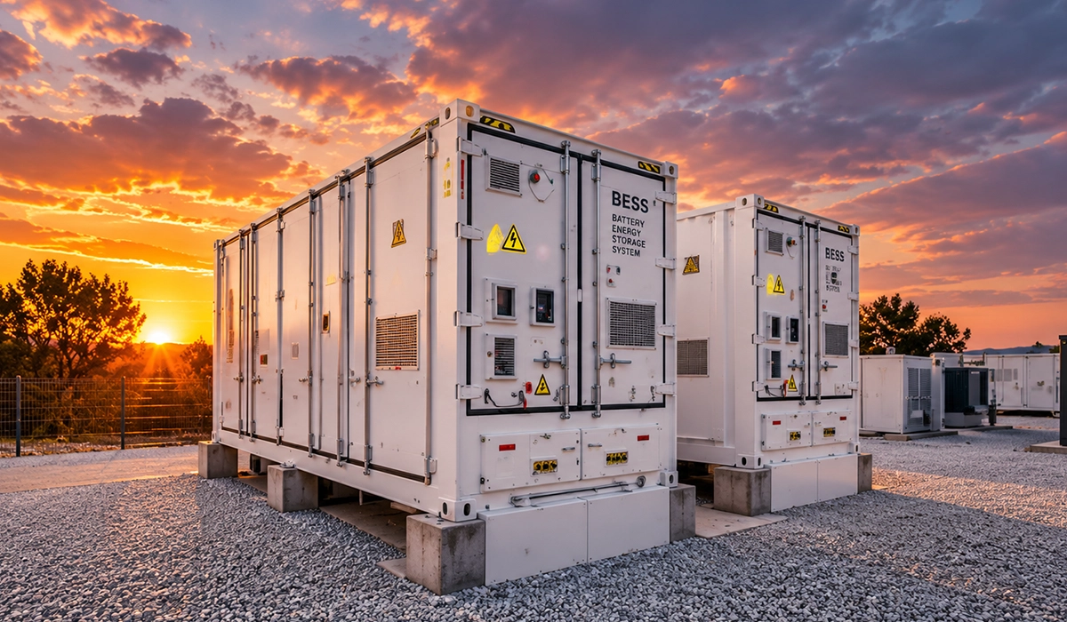
So, what are the main parts of a BESS? Every system has the same core BESS components: batteries to store energy, converters to move it, and software to control it. Good battery energy storage system design treats them as one BESS architecture rather than a shopping list.
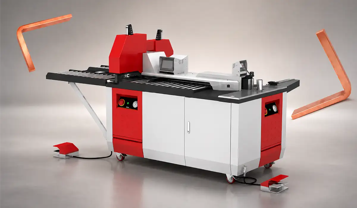
The PAYAPRESS DUC-100 wiring duct cutter delivers clean, accurate cuts for plastic wiring ducts used in electrical control panels. Its adjustable cutting head and HSS blade simplify duct preparation and improve installation efficiency.
Battery Racks and BMS
Cells form modules, and modules connect in series inside each battery rack to reach the system voltage, often 1,000–1,500 V DC on utility projects (typical). Racks then run in parallel to build energy capacity. Each rack usually includes a switch box with contactors, fuses and a current sensor, so a faulty rack can disconnect without stopping the site.
The battery management system watches every cell. It measures voltage, temperature and current, estimates state of charge, balances cells and opens contactors when limits are exceeded. In most designs, the BMS works in layers: module, rack and system level. As a result, the system can protect a single cell while still reporting one clear status to the controls above.
Busbars tie these components together, from the rack terminals to the PCS and transformer. For the fundamentals of busbar types, design and applications, see our guide to electrical busbar systems.
PCS, Inverter and DC/DC Converter
The power conversion system (PCS) moves energy between the DC battery and the AC grid. At its core sits a bidirectional inverter, which charges the batteries in one direction and discharges them in the other. Some designs also add a DC/DC converter between the racks and the inverter. That converter adapts the changing battery voltage to a fixed DC bus, and it lets batteries share a bus with solar panels. On larger sites, a medium-voltage transformer then connects the PCS to the grid. In addition, the PCS handles reactive power, grid-code ride-through and, in newer designs, grid-forming control, so its settings matter as much as its rating.
EMS and Thermal Management
The energy management system decides when the battery charges, discharges or rests. It follows price signals, grid operator commands and site limits, and it passes set points to the PCS. Meanwhile, thermal management keeps cells in their preferred temperature band, because heat speeds up ageing and cold limits power. Air cooling suits smaller systems, whereas liquid cooling now dominates dense utility containers (typical). Both approaches need auxiliary power, which reduces net efficiency. The EMS should therefore count fans, chillers and controls when it plans each charge and discharge cycle.
AC-Coupled vs DC-Coupled BESS
The coupling choice decides where the battery meets the rest of the plant, so it shapes cost, efficiency and flexibility. Comparing DC coupled vs AC coupled BESS options makes most sense when the battery shares a site with solar.
An AC coupled BESS has its own inverter and connects on the AC side, next to the solar inverters or the grid connection. Therefore, it suits retrofits, stand-alone grid services and sites where the battery must charge freely from the grid. However, solar energy that charges the battery passes through two conversions, DC to AC and back to DC, which costs some round-trip efficiency. Round-trip efficiency is the share of charged energy that comes back out, and lithium-ion systems typically reach about 85–90% from AC to AC (typical).
A DC coupled BESS, in contrast, joins the solar array on a shared DC bus, usually through a DC/DC converter, before a common inverter. As a result, it can capture solar energy that the inverter would otherwise clip, and it avoids a second inverter. On the other hand, the shared inverter limits total export when solar output is already high. Some tightly coupled designs also charge only from solar, which can qualify for incentives but limits grid services.
| Factor | AC coupled | DC coupled |
|---|---|---|
| Best fit | Retrofit, stand-alone, grid services | New solar plus storage |
| Inverters | Separate for battery and solar | Shared inverter |
| Solar-to-battery losses | Two conversions | Fewer conversions |
| Clipped solar capture | Not available | Available |
| Grid charging | Unrestricted | Possible; depends on design and incentives |
| Export limit | Battery and solar inverters add up | Shared inverter caps total output |
So, DC-coupled or AC-coupled: which is better? Neither wins every time. Instead, the use case, the grid connection limit and local incentive rules decide. For example, a stand-alone battery selling grid services gains little from DC coupling, whereas a new solar farm with a tight export limit often benefits.
Published modelling shows how small design choices change the value of each layout. NREL’s study compares independent, AC-coupled, DC-coupled and tightly coupled solar-plus-storage plants in its solar storage study.
Each coupling option also changes how the DC and AC buses are arranged on site. Compare the common layouts in our guide to busbar arrangements.
Sizing a Battery Energy Storage System
So, how to size a battery energy storage system? Sizing links the job the battery must do to two numbers: power in MW and energy in MWh. Good BESS sizing then adds margins for losses, ageing and the usable state of charge window.
Clear definitions prevent most sizing errors, especially between power, energy and duration. NREL explains rated power, energy capacity, duration, state of charge and round-trip efficiency in its grid battery FAQ.
Once power and energy are fixed, the DC current sets the size of every bar between the racks and the PCS. Our copper busbar calculator guide shows how to turn that current into a cross-section.
Define the Use Case
First, define what the battery must do and for how long. Peak shaving needs enough power to cut the highest demand, often for one to two hours. Energy shifting, such as moving solar output to the evening, usually needs three to four hours. Frequency response, by contrast, needs high power for minutes and little energy. Next, note the grid connection limit, the expected cycles per day and the required project life. These inputs set the duration and the C-rate, which is the charge or discharge power divided by energy capacity. For instance, a four-hour system runs near 0.25C.
Sizing Steps and Worked Example
Work through these steps in order:
- Set the power at the point of connection and the energy the grid must receive.
- Add conversion losses between the battery and the grid.
- Divide by the usable state of charge window.
- Allow for capacity fade over the project life, or plan augmentation.
- Check the C-rate against the cell and rack limits, then confirm the result with the supplier’s data.
For example, a site needs 10 MW for four hours, so the grid must receive 40 MWh (hypothetical estimate). With about 94% one-way efficiency from battery to grid, the battery must deliver about 42.6 MWh (hypothetical estimate). If the usable window is 90% of nameplate, the starting capacity becomes about 47.3 MWh (hypothetical estimate). Auxiliary loads for cooling and controls add a little more, so many designers round up at this stage.
Next, suppose capacity falls to 85% by year ten without augmentation. In that case, the nameplate grows to about 55.6 MWh (hypothetical estimate). At that size, 10 MW equals roughly 0.18C, which most lithium iron phosphate racks handle easily (hypothetical estimate). Finally, divide by the energy per container to count enclosures. At about 5 MWh per container, that gives 12 containers (hypothetical estimate). Then check that the DC current per PCS stays within busbar and fuse ratings. Alternatively, a smaller first build with planned augmentation can lower upfront cost, although it needs space and connection points for later racks.
DC Busbar and Rack Interconnection Design
The DC side carries every ampere the battery delivers, yet rarely gets its own design chapter. BESS DC busbar design covers the bars that join racks, combiner sections and the PCS input, and it decides losses, fault safety and assembly time. In short, this is where battery energy storage system design meets heavy current.
Fault levels on the DC side set the rating of every bar, fuse and joint downstream of the racks. Mersen’s guide notes that single racks supply about 1–12 kA of fault current, while combined sections can reach 250 kA or more, in its overcurrent protection guide.
Fault currents at these levels also stress bars and supports mechanically. Learn how to check them in our article on short-circuit withstand.
Current and Fault Level
Normal current is easy to estimate. For example, a 2.5 MW PCS at 1,200 V DC draws about 2,100 A from its DC bus (hypothetical estimate). Fault current is the harder part.
So, why is BESS fault current dangerous? A battery cannot be switched off like a generator, because the energy sits in the cells. In addition, DC current has no natural zero crossing, so an arc keeps burning until something interrupts it. Good BESS fault current protection therefore places a DC fuse at the rack, the section and often the PCS input. Each busbar must also withstand the peak let-through current and the magnetic forces of that fault. Fault studies should therefore cover the worst case, with every rack connected and fully charged.
Materials, Insulation and Clearances
Most designs use tin-plated copper, because it combines high conductivity with stable bolted joints. Aluminium, in contrast, saves weight on long runs, but it needs larger sections and careful joint design. At 1,500 V DC, clearance and creepage distances matter as much as cross-section, so designers follow insulation coordination rules for the site’s altitude and pollution level. Many BESS rack interconnection busbar designs therefore use epoxy coating, heat-shrink sleeves or laminated assemblies. Finger-safe covers then protect technicians during maintenance, while the bars stay easy to inspect. In addition, supports must hold the bars against fault forces and container vibration during shipping. Spacers and clamps should therefore use materials rated for both the voltage and the operating temperature.
Fabrication and Bolted Joints
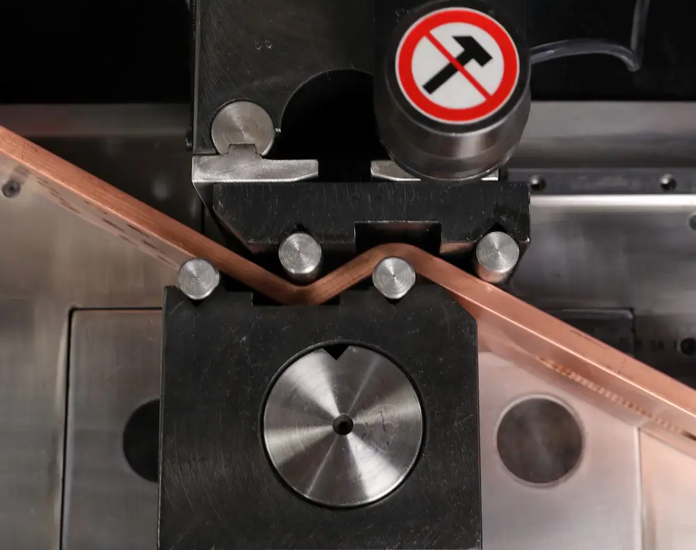
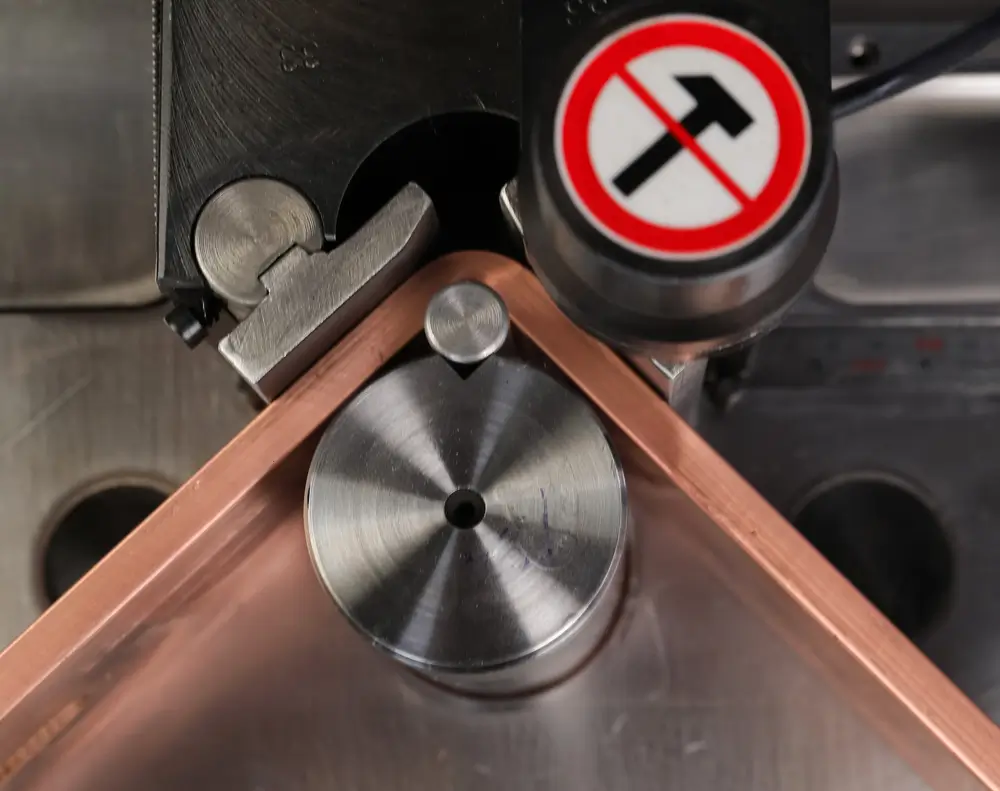
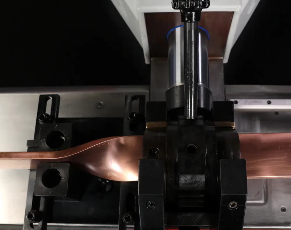
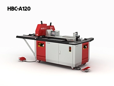
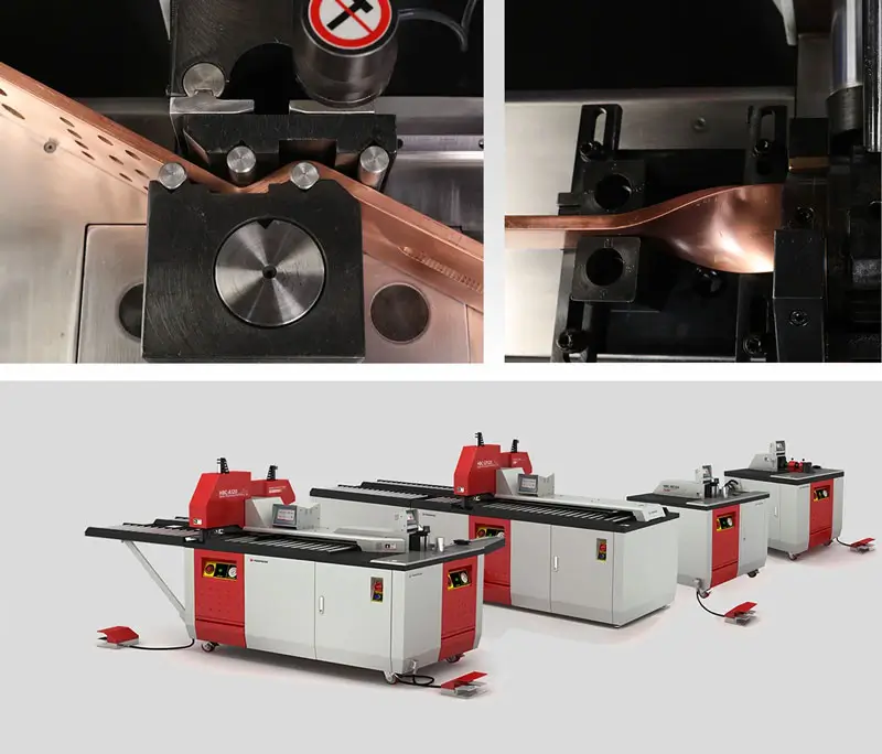
On the machine side, BESS bars are short, numerous and repetitive. A 20-foot container can hold dozens of near-identical rack links (typical; varies by design), so stored CNC programs for cutting, punching and bending pay off quickly. Clean shear cuts and burr-free holes keep contact faces flat. Bends must hold their angle within tight limits, because rack terminals leave no room for forcing a bar into place.
Joint preparation completes the job. Plated faces should be clean, not abraded, before assembly. Then tighten each bolt to the specified torque, add disc spring washers where the design calls for them, and mark the torque. Finally, an infrared check at commissioning confirms that no joint runs hotter than its neighbours.
Protection, Fire Safety and Standards
So, what standards apply to BESS design? Several documents cover the battery, the system and the installation, and most projects need more than one (check the current edition of each):
- UL 9540: safety standard for complete energy storage systems and equipment.
- UL 9540A: test method for thermal runaway fire propagation, from cell to installation level.
- UL 1973: batteries for stationary and motive auxiliary applications.
- NFPA 855: installation of stationary energy storage systems, including separation and size limits.
- IEC 62933 series: electrical energy storage systems, with Part 5-2 covering safety of grid-integrated electrochemical systems.
- IEC 62619: safety of industrial lithium cells and batteries.
- IEC 60269-7: fuses for battery protection, including gBat and aBat classes.
- IEC 62477-1: safety of power electronic converter systems, such as the PCS.
- UL 1741: inverters and converters for distributed energy resources in North America.
Fire safety, however, goes beyond test reports and certificates. Lithium-ion cells can enter thermal runaway and release flammable gas, so containers need gas detection, explosion venting or exhaust, and a fire suppression approach agreed with the local fire service. Water-based systems often suit module fires better than gaseous ones, although site conditions decide. Early detection matters most, so many designs combine off-gas sensors, smoke and heat detection, and alarms linked to the control room. Equally, the design should plan for fire water run-off and for safe access once a fire is out.
Electrical protection completes the safety picture on the DC and AC sides. Ground-fault monitoring, rack contactors and DC fuses isolate faults quickly. In addition, emergency stop circuits and clear isolation points let crews make the system safe before work. Insulation monitoring on the DC bus also helps, because it flags a first earth fault before a second one creates a short circuit.
Large-scale fire testing now shapes permits as much as electrical design does. UL Solutions describes how UL 9540A tests cells, modules, units and installations, and why NFPA 855 cites it, in its UL 9540A overview.
Busbars inside BESS containers must also meet their own design and test requirements. For an overview of the key rules, see our guide to busbar standards.
Layout and Containerization
Good BESS container layout design starts with one choice: containers outdoors or racks in an indoor room. Containers arrive factory-built and tested, so they install quickly and keep fire risk away from occupied buildings. Indoor rooms, by contrast, suit sites with little outdoor space, but they need fire-rated walls, ventilation and stricter code checks.
Inside a container, aisles must leave room to service racks and replace modules. Front-access designs save space, whereas walk-in layouts make inspection easier. Between containers, separation distances limit fire spread, and the gaps must stay clear. For example, NFPA 855 sets a 3 m (10 ft) default that mitigations can reduce, while insurers may ask for more. Place the PCS skids and transformers close to the battery blocks, yet outside the fire separation zone.
Route DC busbars and cables from the racks to the PCS by the shortest practical path. Keep DC and AC routes separate, and plan trenches, trays and penetrations at the layout stage. Finally, give emergency crews two independent access routes to the site, with clear signage at each gate. Crane access for container delivery and later replacement also belongs on the first layout drawing.
Separation and access rules vary between standards, so a regulator’s summary helps early planning. The UK government’s guidance compares NFPA 855 and FM Global separation distances and covers access, venting and fire service liaison in its grid storage guidance.
Rack and container layouts often need conductors that absorb vibration and small misalignments. Our guide to flexible busbar types explains where they fit best.
Conclusion: BESS Architecture and Core Components
Battery energy storage system design works best when every layer is planned together. Choose the coupling for the use case, size for losses, window and ageing, and treat the DC busbar as a core component rather than an afterthought. Then protect the system against DC faults and fire, and lay it out for service and emergency access. That way, the plant stays safe and serviceable for its whole life.
At 1,500 V DC, spacing matters as much as cross-section in every busbar run. Our article on busbar clearances explains how to set safe distances.


Rate this article
Choose a rating from 1 to 5 stars.
No ratings yet