


In practice, busbar clearances and creepage distances must be set before copper routing, support selection, and enclosure design are frozen. That is why experienced panel builders treat electrical clearance, creepage distance, and busbar spacing and sizing as early design inputs rather than late-stage checks.
If you’d rather listen than read, feel free to play the audio file below for the rest of this article.
Difference Between Clearance and Creepage Distance
| Clearance | Creepage | |
|---|---|---|
| What it is | Shortest distance through air | Shortest path along an insulating surface |
| Failure it prevents | Flashover during transient overvoltage | Surface tracking, carbonisation, leakage |
| Driven by | Uimp, overvoltage category, altitude | Insulation voltage, pollution degree, CTI group |
| Timescale | Microseconds — an impulse event | Years — progressive degradation |
| Fix if too small | Increase the air gap | Increase surface path, add ribs or grooves, better material |
| Altitude affects it? | Yes — air thins above 2000 m | No |
The last row is the easiest way to remember which is which. Air gets weaker with altitude; an insulating surface does not. That is why only clearance carries an altitude correction factor.
In busbar clearances and creepage distances, the first distinction is simple but critical. Clearance is the shortest distance through air between conductive parts; in design terms, it is driven mainly by transient stress, rated impulse withstand voltage (Uimp), and altitude.
Creepage distance is the shortest path along an insulating surface between conductive parts. It is governed by working or insulation voltage, pollution degree, and insulating material group, not just by physical air gap. To better understand the fundamentals, see our comprehensive overview of what is a busbar and how it works.
The design objective also differs. Clearance prevents flashover through air during overvoltage events, while creepage limits surface tracking, carbonization, and long-term leakage across insulation under contamination, humidity, or condensation.
That is the real difference between clearance and creepage distance in electrical engineering: one controls dielectric breakdown in air, the other controls surface failure on insulation. Passing one check does not automatically satisfy the other.
| Rated insulation voltage (V) | Min. clearance PD2 (mm) | Min. clearance PD3 (mm) | Min. creepage PD2 (mm) | Min. creepage PD3 (mm) |
|---|---|---|---|---|
| ≤ 250 | 1.5 | 3.0 | 2.5 | 4.0 |
| ≤ 500 | 3.0 | 5.5 | 5.0 | 8.0 |
| ≤ 690 | 5.5 | 8.0 | 8.0 | 12.5 |
| ≤ 1000 | 8.0 | 11.0 | 14.0 | 22.0 |
The Role of Comparative Tracking Index (CTI) in Creepage Distance Specification
CTI explains why the same voltage can require different creepage paths on different insulators. IEC 60112 defines the tracking test; common material groups are I (≥600), II (400–599), IIIa (175–399), and IIIb (100–174). Higher CTI means better resistance to tracking, so thermosets, epoxy-glass systems, and ceramics can often justify shorter creepage than weaker organic surfaces at the same electrical stress. When selecting insulating materials for busbar systems in power distribution applications, CTI classification directly influences spacing decisions.
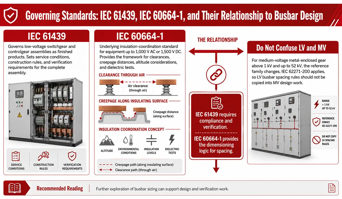
Busbar Clearance as per IEC: How 61439 and 60664-1 Fit Together
IEC 61439 governs low-voltage switchgear and controlgear assemblies as products. It sets service conditions, construction rules, and verification requirements for the finished assembly, but it is not the basic source of the spacing values themselves. For those building or verifying a low-voltage power distribution board, understanding which standard governs which parameter is essential.
IEC 60664-1 is the underlying insulation-coordination standard. It applies to equipment up to 1,000 V AC or 1,500 V DC, includes altitude guidance, and provides the framework for determining clearances, creepage distances, and dielectric tests.
That relationship matters because panel builders often treat the two documents as interchangeable. They are not: IEC 61439 tells you the assembly must comply and be verified, while IEC 60664-1 provides the dimensioning logic behind the required spacing.
For medium-voltage metal-enclosed gear, the reference family changes. IEC 62271-200 covers AC metal-enclosed switchgear above 1 kV and up to 52 kV, so LV busbar spacing rules should not be copied into MV design work.
The practical division is easy to remember once it is stated plainly:
| IEC 60664-1 | IEC 61439-1 | |
|---|---|---|
| What it is | Insulation coordination — the underlying method | Product standard for LV assemblies |
| Answers | How large should the distance be? | Has the assembly been verified? |
| Scope | Equipment to 1000 V AC / 1500 V DC | The finished switchboard |
| Where the values sit | Tables F.1, F.2, A.2 | Section 10.4, Tables 1 and 2 |
| You need it when | Dimensioning the layout | Proving compliance and CE marking |
IEC 61439-1 does not derive its own spacing values. Section 10.4 refers back to IEC 60664-1 and reproduces the relevant tables. If the two ever appear to disagree, you are reading different table conditions, not a conflict between standards.
For the wider verification and CE marking picture, see our IEC 61439 design verification guide.
Further exploration of busbar sizing can be found in the following recommended reading.
Routine Verification vs. Type Testing: What Panel Builders Must Do Under IEC 61439
Type testing establishes a reference design; routine verification checks every manufactured assembly. Under IEC 61439, routine verification includes clearance and creepage assessment, while dielectric properties can be checked with power-frequency withstand tests on main circuits when direct confirmation is not enough.
That is why a standard installation megger test is not the same as clearance verification. Designers working with busbar design software tools can streamline this verification workflow and reduce the risk of non-compliant assemblies. Public industry guidance around IEC 61439 points to dedicated power-frequency or impulse-based methods for dielectric proof, not casual substitution with general commissioning insulation checks.
Pollution Degree Classification and Its Direct Impact on Busbar Spacing
Pollution degree is one of the most misapplied variables in busbar design. PD1 means essentially clean, sealed conditions; PD2 covers ordinary non-conductive pollution with occasional condensation; PD3 covers conductive pollution or dry contamination made conductive by condensation.
For switchboards in industrial plants, PD3 is usually the defensible starting point, not PD2. That choice matters because busbar clearance requirements for industrial switchgear panels are often dominated by contamination risk rather than by nominal voltage alone. A proper understanding of terminal bus bar design and installation helps engineers apply the correct pollution degree classification from the start.
Creepage reacts much more strongly than clearance when pollution worsens. Published guidance notes that creepage can become several times larger as pollution severity rises, which is why PD2 and PD3 layouts can differ sharply even at the same system voltage.
Designers can respond with sealed enclosures, sleeves, coatings, barriers, and geometry. Ribs, grooves, and contoured insulating surfaces extend the tracking path without a proportional footprint increase, which is why good insulation geometry can outperform flat spacing alone.
Busbar Arcing Prevention: How Spacing Stops a Fault Becoming an Arc
Clearance and creepage are usually presented as compliance numbers. They are better understood as arc prevention, because that is the failure they exist to stop.
Three ways a busbar assembly starts arcing, each with a different design control.
1. Impulse flashover across air. A switching or lightning transient exceeds what the air gap can withstand, and current jumps between phases or to earth. The control is clearance, sized from Uimp. This failure is instantaneous and leaves little evidence beyond the arc damage itself.
2. Surface tracking across insulation. Contamination and moisture form a conductive film on an insulator. Small leakage currents dry parts of that film, creating scintillation, which carbonises the surface. The carbon track grows over months or years until it bridges the gap. The control is creepage, sized from insulation voltage, pollution degree and CTI. This one is progressive, which means it is also inspectable.
3. Mechanical collapse into an adjacent phase. Short-circuit force deflects the bar or fractures a support insulator, and the conductor physically moves into the neighbouring phase. The control here is support spacing and section stiffness, not spacing tables. Our busbar short-circuit withstand guide works through the force calculation.
| Measure | Prevents | Cost |
|---|---|---|
| Correct clearance from Uimp | Impulse flashover | Free at design stage |
| Correct creepage from PD and CTI | Surface tracking | Free at design stage |
| Higher CTI insulator material | Tracking | Low |
| Ribs and grooves on insulators | Tracking | Low — geometry, not space |
| Higher IP enclosure rating | Contamination ingress | Medium |
| Heat-shrink sleeving on bars | Both, plus touch safety | Medium |
| Barriers between phases | Flashover and arc propagation | Medium |
| Internal arc classification to IEC/TR 61641 | Contains an arc once started | High |
Notice the split in that table. Everything except the last row is about stopping an arc. Internal arc classification is about surviving one. They are not alternatives — a panel with proper spacing and no arc containment is normal and compliant. A panel with arc containment and undersized spacing is a panel that will eventually test its containment.
The most common real cause of arcing is not a calculation error. It is a bar that was fabricated slightly off drawing, forced into position during assembly, and left with 5 mm where the drawing said 8 mm. Clearance designed on paper only survives if the copper is cut, punched and bent to the dimensions the drawing specifies.
How to Calculate Busbar Clearance from Uimp: Worked Example
Clearance is driven by transient stress, so overvoltage category matters first. OVC I applies to specially protected internal circuits, OVC II to ordinary connected equipment, OVC III to fixed distribution equipment such as switchboards and MCCs, and OVC IV to origin-of-installation equipment.
IEC 60664-1 selects Uimp from overvoltage category and rated voltage, then uses the corresponding impulse value to determine minimum clearance. Public excerpts of Table F.1 and F.2 show the logic clearly: higher category means higher impulse duty, which means more air gap.
For what is the busbar spacing for 1000V rated insulation voltage, the public IEC excerpt supports this chain: OVC III maps to 8 kV, and 8 kV maps to an 8 mm minimum air clearance at up to 2,000 m. That is the core clearance result in the common 1,000 V LV distribution example. For a deeper look at how power factor also affects system performance alongside insulation design, see our guide on power factor in electrical systems.
Creepage follows a different chain, and it needs one input that clearance does not: the insulating material group. Rated insulation voltage, pollution degree and material group together select the value from IEC 61439-1 Table 2. A creepage figure quoted without its material group is incomplete — the same 1000 V bar in pollution degree 3 needs a different surface path on a Group I ceramic than on a Group IIIa organic insulator.
That is the most common mistake in creepage specification: treating it as a function of voltage alone, the way clearance almost is.
| Worked example input | Verified public output |
|---|---|
| Ui = 1000 V | LV equipment scope applies |
| Overvoltage category = III | Uimp = 8 kV |
| Pollution degree = 3 | Industrial micro-environment |
| Clearance result | 8 mm at ≤ 2000 m |
Practical Design Considerations: Bare vs. Insulated Busbars, Altitude, and Safety Margins
In applied design, busbar clearances and creepage distances are rarely controlled by tables alone. Bare copper rails and bare aluminum rails need the full air-gap discipline of the standard, while insulated systems can sometimes package more tightly if the insulation system has been properly qualified. For specialized applications, flexible busbar types, sizing, and standards offer an alternative routing approach where clearance geometry differs from rigid rail layouts.
That is the essential bare-versus-insulated boundary. Bare vs insulated is not just copper with sleeve versus copper without sleeve; it is verified dielectric performance versus reliance on air. If the coating ages, cracks, or loses thermal integrity, the design effectively falls back toward bare-busbar behavior.
Altitude adds another correction. IEC 60664-1 applies normal values up to 2,000 m, and ABB’s public extract of Table A.2 shows kd factors of 1.14 at 3,000 m, 1.29 at 4,000 m, and 1.48 at 5,000 m for clearance correction.
Experienced designers also leave practical headroom. Dust settles on horizontal flats faster than on vertical edges, humidity shifts micro-environments, and late hardware changes erode margins. A layout that meets the table exactly on the drawing often does not meet it after three years of service and one panel modification.
Support Spacing: Keeping the Clearance You Designed
A clearance is only real if the bar stays where you put it. Short-circuit force deflects conductors, and if deflection exceeds the phase gap, the designed clearance disappears at exactly the moment it matters most. Greater section stiffness reduces that movement — the CDA’s Copper for Busbars guide notes that a higher moment of inertia limits deflection for a given span.
Support spacing is therefore an insulation parameter, not only a mechanical one. The force calculation and span selection are covered in our busbar short-circuit withstand guide.
Conclusion: Designing Safer Busbar Systems Starts with Correct Spacing
Busbar clearances and creepage distances are not minor layout details; they are essential safety parameters that directly affect arc resistance, insulation reliability, dielectric strength, and long-term assembly performance. In low-voltage assemblies, IEC 61439 defines the need for proper verification, while IEC 60664-1 provides the insulation-coordination method behind clearance and creepage selection. For this reason, panel builders should consider busbar spacing from the earliest design stage, before copper routing, support placement, enclosure layout, and insulation systems are finalized.
Manufacturing accuracy is equally important, which is why many manufacturers use a Busbar fabrication machine to produce busbars with precise cuts, bends, and hole patterns that support reliable installation and long-term electrical performance.
A reliable busbar design starts with the correct classification of rated insulation voltage, overvoltage category, pollution degree, altitude, and insulating material group. However, compliance is not only about meeting a table value; it also requires practical engineering judgment for real operating conditions such as dust, humidity, vibration, heat, and future maintenance changes. To explore emerging approaches in this field, see our article on future trends in busbar systems. Correct clearance and creepage planning is one of the clearest signs of a professionally engineered, safe, and resilient low-voltage assembly.