


If you’d rather listen than read, feel free to play the audio file below for the rest of this article.
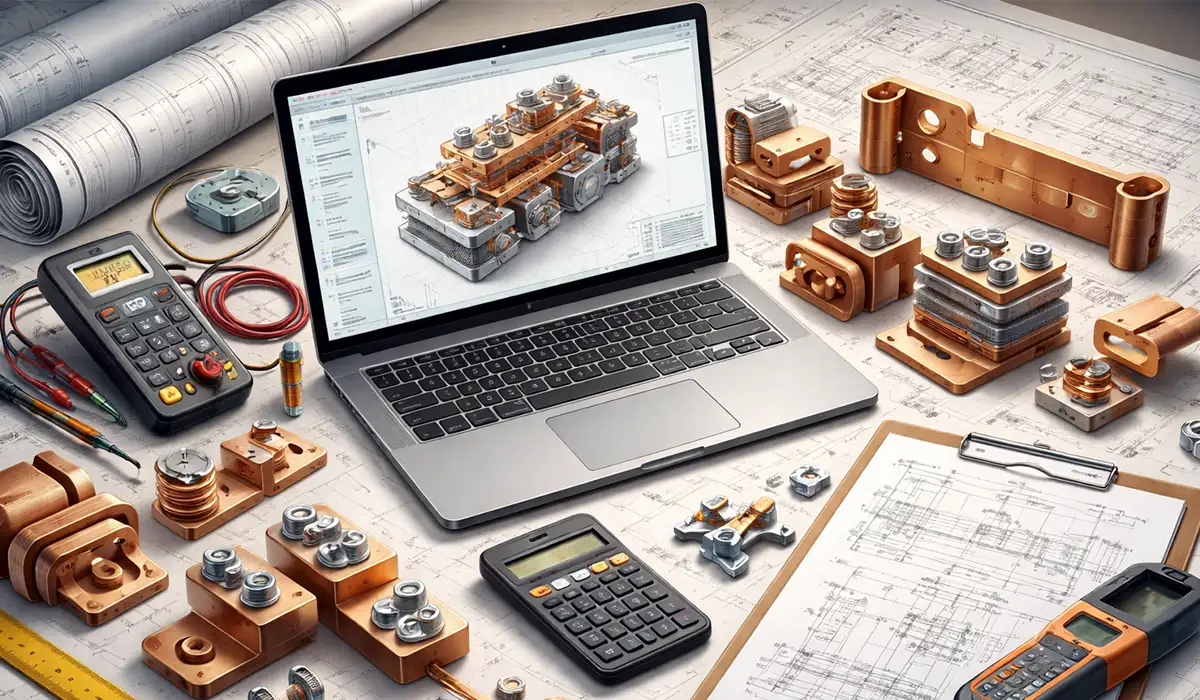
How to Select the Right Busbar for Your Panel: A Complete Engineer’s Guide
Busbar choice sets thermal margin, fault survival, voltage drop, joint reliability, and future expandability for the whole assembly. A good design balances rated current, prospective short-circuit current, temperature rise, spacing, insulation coordination, corrosion exposure, and cost. This guide gives a practical selection workflow for LV switchgear, distribution boards, MCCs, and power panels, then ties the result back to IEC 61439 verification.
If you are looking for more information about Electrical Power Distribution, it is recommended not to miss reading this article.
Why Busbar Selection Is a Critical Engineering Decision
For anyone working through how to select the right busbar for your panel, the first lesson is simple: busbar design is not a metal-stock decision. It is a system decision that affects the full assembly.
A bar that is acceptable for continuous current can still fail during a fault if the short-circuit level, peak force, or support spacing was underestimated. That is where real field failures begin.
A good step by step busbar selection process for LV switchgear panel builders must satisfy thermal, electrical, mechanical, environmental, and economic limits at the same time. Skipping one layer usually pushes cost or risk into another.
Further exploration of what is busbar can be found in the following recommended reading.
That is why experienced panel builders document busbar material, cross-section, withstand rating, insulation choice, and service conditions as part of the compliance file, not as workshop afterthoughts. For an authoritative framework, review the IEC 61439-1 assembly standard.
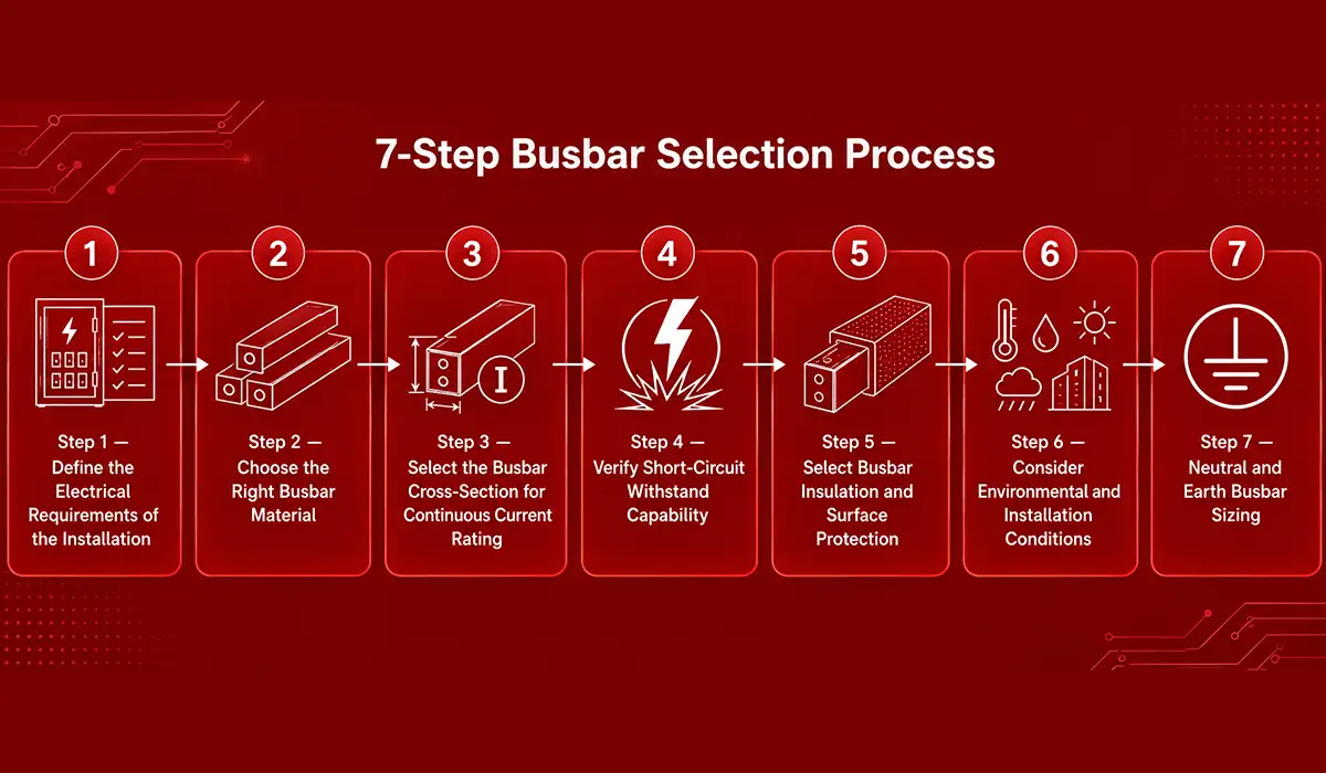
Step 1 — Define the Electrical Requirements of the Installation
Before selecting any bar size, gather the electrical inputs that govern how to select busbar size based on current rating and fault level. In practice, these values come from the single-line diagram, protection study, and site conditions.
| Required input | Why it matters |
|---|---|
| Rated system voltage | Drives insulation coordination and spacing |
| Rated continuous current (In / Ib) | Sets the base thermal loading |
| Prospective short-circuit current (PSCC) | Sets thermal and dynamic fault duty |
| Fault clearing time | Determines fault energy seen by the bar |
| Frequency, 50/60 Hz | Affects skin effect and reactance behavior |
| Phase arrangement: L1, L2, L3, N, PE | Defines conductor count and geometry |
PSCC and clearing time must be treated as a pair. Many panels are sized correctly for normal load but still under-designed for fault duty because only steady-state current was checked.
If you are looking for more information about power factor, it is recommended not to miss reading this article.
PSCC and clearing time must be treated as a pair. Many panels are sized correctly for normal load but still under-designed for fault duty because only steady-state current was checked.
In commercial terms, this is also the point where procurement risk is reduced. If the engineer defines current, fault level, and service conditions early, the workshop can choose a busbar system without later redesign. For the standard method of calculating prospective fault currents, consult the IEC 60909 short-circuit calculation standard.
If you are looking for more information about busbar arrangements, it is recommended not to miss reading this article.
Step 2 — Choose the Right Busbar Material
Material choice decides conductivity, weight, joint behavior, corrosion tolerance, tooling ease, and installed cost. For many projects, copper vs aluminum busbar selection for LV switchgear panels is the first real design tradeoff.
If you are looking for more information about terminal busbar, it is recommended not to miss reading this article.
Copper Busbars — The Default Choice
Cu-ETP remains the default choice because it combines high conductivity, strong joint performance, good workshop formability, and solid mechanical behavior under fault stress. In most LV switchboards, copper gives the simplest route to compact dimensions and reliable bolted joints.
Aluminum Busbars — When They Make Sense
Aluminum earns attention when weight, material cost, or long main runs dominate the project. The tradeoff is larger cross-section, stricter joint discipline, oxide management, and more care at copper interfaces. In large switchboards, that compromise can still be economically attractive.
Surface Treatments — Tin, Silver, and Bare
Surface finish is a reliability decision, not decoration. Bare copper suits many indoor assemblies, tin plating helps in humid service or repeated joint work, and silver plating is reserved for very demanding contact points where low resistance and stable mating surfaces matter most.
Use the table below as a practical starting point; final approval still depends on the actual assembly layout, joint design, and verification route.
For deeper material guidance on conductivity, jointing, and finishing, see the Copper Development Association busbar reference.
| Property | ETP Copper | Aluminum | Tin-Plated Copper |
|---|---|---|---|
| Conductivity (MS/m) | 58 | 35 | 57 approx. |
| Density (g/cm³) | 8.9 | 2.7 | 8.9 |
| Relative Material Cost | High | Low | Medium-High |
| Joint Complexity | Low | High | Low |
| Corrosion Resistance | Good | Moderate | Very Good |
| Typical Application | All LV panels | Large switchboards | Critical joints |
For a comprehensive understanding of Ground Busbar , we highly recommend reviewing this article.
Step 3 — Select the Busbar Cross-Section for Continuous Current Rating
This is the core sizing step because what factors determine busbar cross-section in electrical panels always comes back to heat. Cross-section, arrangement, enclosure style, and cooling path together determine whether the assembly stays within acceptable temperature-rise limits.
Do not treat busbar rating as a single catalog number. In an LV panel, current carrying capacity changes with spacing, emissivity, ventilation, bar grouping, and how close the conductors sit to hot devices.
If you are looking for more information about Busbar Design Software, it is recommended not to miss reading this article.
Current Density and Temperature Rise Limit
IEC 61439 uses temperature-rise verification, so practical current density is only a starting estimate. For bare copper bars, many LV designers begin around 1.5 to 2.0 A/mm², then correct for enclosure and arrangement before locking the final size.
Derating Factors That Affect Cross-Section Selection
If you are asking how does ambient temperature affect busbar current rating selection, start with derating. Hot rooms, sealed enclosures, close phase spacing, high altitude, and continuous duty all reduce usable ampacity and usually push the next larger conductor cross-section.
The derating table below is a practical design aid for concept-stage sizing. Final values should always be checked against the tested assembly system or the calculation method used for that enclosure. For broader LV switchboard derating practice, the Schneider Electric Installation Guide is a trusted industry source.
Further exploration of Future Trends in Busbar Systems can be found in the following recommended reading.
| Condition | Derating Factor |
|---|---|
| Ambient 40°C (vs 35°C reference) | 0.97 |
| Ambient 45°C | 0.93 |
| Ambient 50°C | 0.89 |
| Sealed enclosure (no ventilation) | 0.80–0.85 |
| 3 busbars touching (flat stacked) | 0.75–0.80 |
| Altitude 2000 m | 0.95 |
Standard Busbar Cross-Sections and Their Approximate Ratings
After derating, choose the next standard size above the calculated requirement. Treat the ratings below as indicative open-air values for concept work, then verify them against the real switchboard geometry and test basis.
| Dimensions (mm) | Cross-Section (mm²) | Approx. Current Rating (A) |
|---|---|---|
| 25 × 3 | 75 | 190–210 |
| 30 × 5 | 150 | 320–350 |
| 40 × 5 | 200 | 400–440 |
| 50 × 5 | 250 | 480–520 |
| 60 × 10 | 600 | 860–940 |
| 80 × 10 | 800 | 1100–1200 |
| 100 × 10 | 1000 | 1300–1450 |
Step 4 — Verify Short-Circuit Withstand Capability
This step decides whether the chosen bar survives a real fault. For engineers wondering how to select busbar short-circuit withstand rating for a distribution board, the answer is never “by load current alone.”
Thermal withstand, dynamic force, support spacing, and peak current must all be checked together. Your uploaded note is especially useful here because it emphasizes the same point: thermal survival and mechanical survival are separate checks.
If you are looking for more information about Flexible Busbar, it is recommended not to miss reading this article.
Thermal Withstand — Minimum Cross-Section Under Fault
Use the adiabatic check to confirm the bar can absorb the fault energy for the actual clearing time. If the fault-based area is larger than the continuous-current area, the fault condition governs the final selection.
Dynamic (Electrodynamic) Withstand — Mechanical Strength Under Peak Current
Peak current creates the highest mechanical stress in the first half-cycle, and force rises roughly with the square of current. That means bar spacing, support cleat spacing, and section stiffness matter just as much as conductor area.
Rated Icw and Ipk — Matching to System Fault Level
Icw is the short-time RMS withstand value; Ipk is the first peak the system must survive without unacceptable deformation. Both ratings must meet or exceed the fault level at the installation point, and both must be documented in the assembly verification route.
The recognized method for calculating these mechanical and thermal fault effects is detailed in the IEC 60865 short-circuit effects standard.
Step 5 — Select Busbar Insulation and Surface Protection
This step decides whether a bare conductor is sufficient or whether sleeving, coating, or full insulation is the safer engineering choice. In cramped assemblies, how to choose between insulated and bare busbars in switchgear often becomes a space-versus-access tradeoff.
Insulation choice should follow voltage, pollution degree, overvoltage category, maintainability, and arc-flash exposure. Space pressure alone is not a good reason to ignore creepage or clearance rules.
If you are looking for more information about topic busbar sizing, it is recommended not to miss reading this article.
Bare vs. Insulated Busbars
Bare bars are common in enclosed LV gear where geometry provides safe distances. Insulated bars make more sense when space is tight, contamination risk is higher, or live-work exposure needs to be reduced.
Clearance and Creepage Distance Selection
Clearance depends mainly on voltage and impulse stress; creepage depends strongly on pollution degree and insulating surface condition. The table below is useful for concept design, but the final values must be checked against the exact tables used for the project.
For full coordination principles, refer to the IEC 60664-1 insulation coordination standard.
| Voltage | Pollution Degree | Min. Clearance (mm) | Min. Creepage (mm) |
|---|---|---|---|
| 400V | 2 | 5.5 | 8.0 |
| 400V | 3 | 8.0 | 12.5 |
| 690V | 2 | 8.0 | 12.5 |
| 690V | 3 | 12.5 | 20.0 |
Step 6 — Consider Environmental and Installation Conditions
A busbar that works indoors may be wrong outdoors, and a design that is stable in a clean switch room may be risky in a corrosive plant. This is where busbar selection criteria for hospitals and critical power applications become much stricter.
Indoor vs outdoor, dry vs condensing, clean vs polluted, and rigid building service vs vibrating machinery are not minor details. They directly change insulation strategy, plating, joint hardware, support design, and maintenance intervals.
High humidity raises tracking risk. Corrosive atmospheres favor tin or silver plating. Vibration argues for better joint locking and clamp design. Higher altitude reduces both cooling and dielectric strength, so electrical and thermal margins both shrink.
Critical facilities such as hospitals, data rooms, and process plants usually justify more conservative current density, cleaner busbar layout, stronger joint control, and easier inspection access because downtime cost is far higher than copper cost. Additional requirements specific to power switchgear assemblies are defined in the IEC 61439-2 switchgear standard.
Step 7 — Neutral and Earth Busbar Sizing
Neutral and PE bars should never be copied blindly from phase dimensions. Harmonics, load type, and fault path all change the answer. In modern panels, neutral sizing is often the most underestimated conductor decision.
In balanced linear loads, a reduced neutral may be acceptable. With UPS systems, VFDs, servers, and LED lighting, third-harmonic currents can accumulate in the neutral, making equal or even larger neutral capacity the safer choice.
The PE bar follows a different logic. It is selected for protective function and fault duty, not routine load current, and the rules for sizing protective conductors are set out in the IEC 60364-5-54 earthing standard.
A practical rule is this: if the installation is rich in non-linear loads, size the neutral by measured or expected harmonic current, not by old assumptions from linear three-phase systems.
Busbar Selection Summary — Decision Checklist
At this point, how to select the right busbar for your panel becomes a verification exercise. The right answer is the smallest busbar system that still meets thermal, fault, insulation, environmental, and documentation requirements with margin.
Confirm rated current, apply derating, then check the fault level and clearing time. After that, lock material, cross-section, spacing, support system, and finish. Only then should you finalize fabrication drawings and select the right busbar machine for cutting, punching, and bending the specified copper or aluminum sections.
Keep copper vs aluminum, bare vs insulated, indoor vs outdoor, and equal-neutral vs reduced-neutral as explicit engineering choices in the design file. When those contrasts are written down, field mistakes drop sharply.
Conclusion: Selecting the Right Busbar Is a Verification Process
Selecting the right busbar for an electrical panel is not simply a matter of choosing copper or aluminum with enough cross-section for the load current. A reliable busbar system must be checked as part of the complete assembly, including continuous current rating, short-circuit withstand, temperature rise, insulation coordination, conductor spacing, support design, environmental exposure, and future maintenance access.
For LV switchgear, distribution boards, MCCs, and power panels, the best approach is to follow a structured engineering workflow. First, define the electrical requirements. Then select the material, calculate the required cross-section, apply derating factors, verify thermal and dynamic short-circuit performance, and confirm clearance, creepage, insulation, neutral sizing, and earthing requirements.
A correctly selected busbar improves more than current carrying capacity. It supports safer operation, better thermal stability, lower voltage drop, stronger fault performance, easier inspection, and more predictable compliance with IEC 61439 verification principles. In practical panel building, this means fewer redesigns, fewer workshop errors, and a more reliable final assembly.
The safest rule is simple: never select a busbar by ampere rating alone. Treat busbar selection as a complete design verification task, and document every major decision before fabrication begins.