









For your convenience, if you prefer listening, you can listen to the rest of this article via the audio file below.
What Is a Flexible Bus Bar? Construction, Materials, and Naming
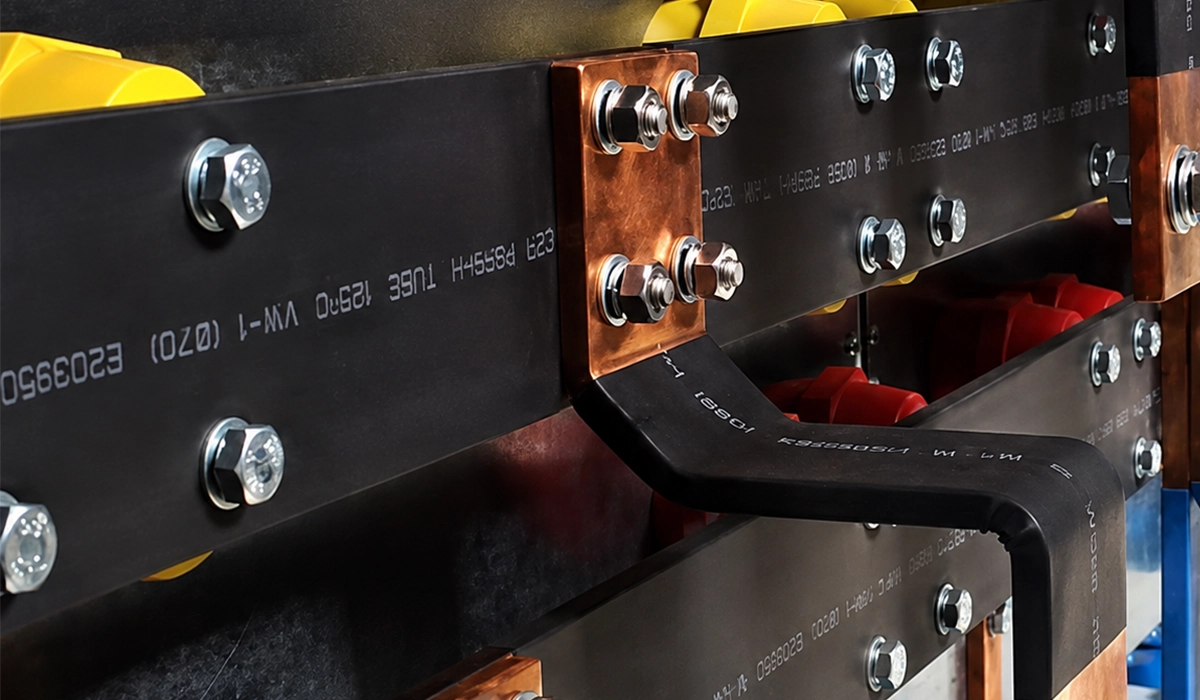
A flexible bus bar is a high-current conductor that combines the electrical performance of solid copper with the mechanical adaptability of a flexible assembly. Instead of one stiff bar or a bundle of round cables, it uses many thin copper elements acting in parallel — either stacked foils or woven strands — held inside an insulating jacket.
That construction is what delivers the three properties buyers are actually paying for:
| IEC 61439 | UL 508A | |
|---|---|---|
| The Rating | Icw — Short-Time Withstand Current | SCCR — Short-Circuit Current Rating |
| How It Is Set | Verified for the Assembly as a Whole | Built from the Weakest Power-Circuit Component (Supplement SB) |
| Duration | Defined, Usually 1 Second | Instantaneous Let-Through Basis |
| Marking | Declared in Technical Documentation | Must Be Marked on the Nameplate |
| Improving It | Heavier Bar, Closer Supports, Current-Limiting Device | Replace the Weakest Component |
Naming. The product is sold under a confusing number of names. All of the following refer to essentially the same family: flexible busbar, flexible bus bar, flexibar, flex busbar, flexi busbar, laminated busbar, braided busbar connector, copper braid shunt, and multilayer busbar. When comparing quotes, ignore the trade name and compare cross-section, permitted temperature rise, insulation class, and termination type.
Where flexible bus systems fit. In a complete distribution design, flexible bars rarely carry the main run. They handle the transitions — switchgear to breaker, transformer to board, module to module — where alignment tolerance, vibration, or thermal movement makes a rigid connection risky.
Laminated vs Braided Flexible Busbar: How to Choose
The two constructions solve different problems. Choosing wrongly is the most common specification error in this product family, and the symptom usually appears months later as a cracked jacket or a hot termination.
| Laminated Flexible Busbar | Braided Flexible Busbar | |
|---|---|---|
| Construction | Thin copper foils stacked flat | Fine copper strands woven together |
| Profile | Flat, rectangular | Flat or rounded, more open |
| Inductance | Low — foils in close parallel | Higher — open weave, larger loop area |
| Flexibility Axis | Bends readily on the flat, resists twist | Bends and twists in all directions |
| Movement Tolerance | Good for one-time forming | Excellent for repeated cycling |
| Current per mm² | Higher — better packing and surface contact | ~10–15% lower for the same nominal section |
| Best for | Power electronics, battery interconnects, tidy panel routing | Vibration, thermal cycling, misalignment, traction |
| Weak Point | Repeated flexing can fatigue foils at the clamp | Higher inductance; strands can fret if unsupported |
The decision rule in one line: if the connection is formed once and stays put, choose laminated. If the connection will move repeatedly — thermal growth, vibration, or a component that shifts — choose braided.
Flexible Laminated Copper Busbar
A flexible laminated copper busbar is built from multiple thin copper foils — typically 0.1 to 0.5 mm each — stacked and then jacketed. Because the foils sit in close parallel, the assembly has lower loop inductance than a round cable of the same section, which matters in fast-switching environments.
Where the low inductance actually pays:
- Inverter and UPS DC links, where switching transients see the loop inductance directly
- IGBT and capacitor stacks, where voltage overshoot scales with inductance
- Battery module interconnects, where a tidy flat profile also saves pack volume
Specification points to state on the drawing:
| Parameter | Why It Matters |
|---|---|
| Number and Thickness of Laminations | Sets flexibility and minimum bend radius |
| Plating (Bare / Tinned / Silver) | Sets joint resistance stability over life |
| Insulation Class and Material | Sets permitted temperature rise |
| Termination Style | Determines whether the layers are properly bonded at the end |
| Minimum Bend Radius | Exceeding it cracks foils and the jacket |
The failure to avoid: never twist a laminated bar or compress the layers beyond the manufacturer’s limit. Both open up micro-gaps between foils, which raises resistance where you cannot see it.
For forming limits on solid copper, our guide to bending copper busbar and minimum radii covers the same principle for rigid bar.
Flexible Braided Busbar and Braided Connectors
A braided busbar is made from bundles of fine copper strands woven into a flat or rounded rope, then terminated at each end onto a rigid connector plate. The braided section between the plates is what absorbs movement.
What the weave buys you:
- Misalignment tolerance. Two busbars that do not line up perfectly can still be joined without stressing either terminal.
- Thermal movement. A bar that grows several millimeters between cold start and full load will not load its terminals.
- Vibration isolation. The weave damps mechanical energy that would otherwise loosen a bolted joint.
Typical applications: traction and rail machinery, generator and transformer terminations, earthing and bonding straps, battery modules under thermal cycling, and any joint that crosses an expansion break.
Two things to specify that buyers often forget:
- Insulated or bare. Braided connectors are commonly supplied bare, with heat-shrink insulation as an option. If the joint is inside a compartment with reduced clearances, specify the insulation explicitly.
- Free length and installed geometry. A braid installed under tension defeats its own purpose. Specify a working length that leaves a deliberate loop.
Flexible Busbar Ampacity Table: Cross-Section vs Current Rating
The table below gives indicative continuous current ratings for a single laminated flexible bus bar, in free air, at a 30 K temperature rise over a 35 °C ambient. The second current column gives the value most panel designers actually need — the same bar inside an enclosure or grouped with other conductors.
| Cross-Section (mm²) | Typical Size (W × T, mm) | Free Air (A) | Enclosed / Grouped, ×0.8 (A) |
|---|---|---|---|
| 20 | 13 × 4 | ~125 | ~100 |
| 40 | 16 × 5 | ~190 | ~150 |
| 63 | 20 × 5 | ~250 | ~200 |
| 100 | 24 × 6 | ~330 | ~265 |
| 160 | 32 × 6 | ~450 | ~360 |
| 250 | 32 × 10 | ~600 | ~480 |
| 400 | 50 × 10 | ~830 | ~665 |
| 630 | 63 × 12 | ~1150 | ~920 |
| 800 | 80 × 12 | ~1380 | ~1105 |
| 1000 | 100 × 12 | ~1650 | ~1320 |
| 1200 | 120 × 12 | ~1900 | ~1520 |
Indicative values for concept design only. Confirm against the specific manufacturer’s data before issuing a design.
Four things this table teaches:
- Braided runs lower. For the same nominal cross-section, a braided bar typically carries 10–15% less than a laminated one. The open weave has more air gaps and less effective contact surface.
- Catalogue figures above ~2000 A usually assume something. When a vendor quotes 2800 A on a single flexible bar, check the small print — it normally means a higher permitted rise (often 105 K on tinned copper with high-temperature insulation) or parallel bars, not a like-for-like comparison with the values above.
- Insulation class caps the rating, not the copper. A PVC-jacketed bar limited to 90 °C will hit its insulation limit long before the copper is in trouble. Silicone or high-temperature jackets unlock the higher figures.
- Grouping bites harder than ambient. Three flexible bars run tight together in a duct lose more capacity than the same bars in a 45 °C room with space around them.
For the underlying thermal method and a full derating walkthrough, see our copper busbar current ratings guide and the copper busbar calculator.
Flexible Busbar vs Cable vs Rigid Bar: A Direct Comparison
| Flexible Busbar | Cable | Rigid Copper Bar | |
|---|---|---|---|
| Space Used per Amp | Low | High | Lowest |
| Routing Around Obstacles | Easy | Easy | Difficult — needs machining |
| Tolerates Movement / Vibration | Yes | Partly | No |
| Loop Inductance | Low (laminated) | High | Low |
| Terminations per Connection | 2 | 2 per conductor × parallel sets | 2 |
| Installation Labor | Low | High | Medium — needs fitting |
| Material Cost per Meter | High | Low | Medium |
| Total Installed Cost at High Current | Competitive | Rises with parallel sets | Competitive if layout is simple |
| Best Fit | Transitions, tight routes, moving joints | Long simple runs, low current | Long fixed high-current runs |
The honest summary: flexible bus bar is not a general-purpose replacement for either. It wins specifically where a rigid bar cannot be routed or cannot tolerate movement, and where cable would need multiple parallel sets. On a straight 30 meter run at 200 A, cable is still the right answer.
Space, Inductance & Thermal Performance
Because laminated flexible busbars use stacked copper foil, they often have lower loop inductance than round cables. Lower inductance helps reduce electrical noise and improves performance in fast-switching environments like inverters and UPS systems. Their flat geometry also spreads heat over a larger surface area than a round bundle of cables, helping with thermal management.
Vibration, Tolerance & Assembly
Braided flexible busbars are prized where vibration and mechanical tolerance are issues. The interwoven structure absorbs movement and reduces stress on terminals, which is critical in battery packs, transport applications, and machinery that cycles temperatures or load frequently. Their flexibility also speeds installation because you don’t need precise rigid bends or special terminations.
For a comprehensive understanding of Flexible Cable , we highly recommend reviewing this pdf.
Flexible Busbar Connectors and Joint Types
A flexible bus bar is only as good as its two ends. Because the conductor is made of many thin elements, the termination has to do something a cable lug never does: bond all the layers or strands into one solid, low-resistance block before the bolt is even tightened.
Get this wrong and current crowds into the outer layers, the inner ones carry less, and the joint runs hot at a load the bar itself handles easily.
Busbar Connector Types: Crimped, Welded, Forged, and Bolted
| Termination Type | How It Works | Best For | Watch-Out |
|---|---|---|---|
| Forged / Compacted End | Layers pressed into a solid pad, then drilled | Laminated bars, factory-terminated | Cannot be made on site |
| Diffusion Welded | Layers fused into one block | High current, high reliability | Highest cost; factory only |
| Crimped Lug | Compression barrel over the conductor | Braided bars, field work | Needs the correct die and tool |
| Soldered / Dipped End | Solder wicks between strands, then drilled | Small braided connectors | Solder creeps under thermal cycling |
| Bolted Clamp Plate | Plates sandwich the conductor end | Field-serviceable joints | Must be re-torqued periodically |
| Pre-Assembled Flexibar | Conductor supplied with both ends finished | Repeat builds, volume assembly | Length fixed at order stage |
The rule that applies to all of them: the termination must be matched to the conductor’s layer structure. A crimp die sized for stranded cable will not compact a laminated stack correctly, and a lug intended for a laminated pad will not grip a loose braid.
How to Make a Reliable Flexible Busbar Joint
The joint itself follows the same physics as any bolted copper connection — contact area, contact pressure, surface condition — with two extra rules that come from the flexible construction.
The standard five steps:
- Clean both mating faces to bright metal, or confirm the plating is intact and unmarked.
- Match the contact area to at least the conductor’s cross-section.
- Fit Belleville (disc spring) washers on every bolt. Copper creeps under thermal cycling; a plain washer loses clamping force, a disc spring does not.
- Torque to specification and mark the bolt so any later movement is visible.
- Measure the joint with a micro-ohmmeter and record the reading as the maintenance baseline.
Two rules specific to flexible bars:
- Never let the joint carry the flex. The bending must happen in the free span, not at the termination. Install a deliberate loop or offset so the bar is not under tension at rest.
- Support the free span in vibration. An unsupported braid will fret against enclosure edges and abrade its jacket long before the copper fails.
Flexible Busbar Applications: Switchgear, Transformers, Batteries, and Power Electronics
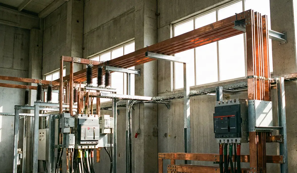
Flexible busbars show up in a surprising variety of places. They’re increasingly common in modern switchgear and power distribution boards where designers want to save space and reduce wiring clutter. In data centers and renewable energy systems, they help organize high-current paths with minimal footprint. This article serves as a valuable resource for those seeking detailed information on Types of Electrical Power Distribution Boards where these components are integrated.
In battery applications such as LiFePO4 packs or electric vehicle traction systems, flexible busbars serve as interconnects between modules, accommodating thermal expansion and vibration while keeping resistance low. They also appear in power electronics inverters, motor drives, and control cabinets where a tidy, low-inductance layout improves reliability.
Transformer Flexible Busbar Connections
The transformer secondary to LV board connection is one of the most common uses for a flexible bus bar, and for four specific reasons:
| Problem at the Transformer | What the Flexible Bar Solves |
|---|---|
| Thermal Growth | The transformer and the board expand at different rates; a rigid link transfers that force into the bushings |
| Vibration | Core hum at twice line frequency will loosen a rigid bolted joint over time |
| Alignment Tolerance | Transformer and board are rarely set perfectly; the flexible section absorbs the offset |
| Very High Current in a Short Span | 1600–4000 A over one or two metres suits copper far better than parallel cable sets |
Three specification points for transformer connections:
- Isolate the bushing from all mechanical load. The flexible section must be the only thing taking movement — never the porcelain or resin bushing.
- Size for the transformer’s full secondary rating, not the board’s diversified load. This link sits upstream of any diversity.
- Check short-circuit forces. At 2000 kVA and above, the peak fault force on the connection is substantial, and a flexible bar with a long unsupported loop can be thrown into adjacent phases.
The force calculation is set out in our guide to busbar short-circuit withstand and mechanical strength.
Battery Pack and EV Module Interconnects
Battery applications combine every condition that favours a flexible bus bar at once: high current, tight volume, repeated thermal cycling, and cells that move.
- Module-to-module interconnects must absorb cell swelling and thermal growth across hundreds of charge cycles without loading the terminals.
- Laminated bars dominate inside the pack because the flat profile saves volume and the low inductance helps at the inverter interface.
- Braided links appear at the pack boundary, where the pack moves relative to the vehicle or enclosure.
- LiFePO4 stationary storage uses the same approach at lower cycling rates but longer service life, so plating quality matters more than flexibility.
Example Configurations
Typical use cases include connecting a breaker or fuse switch disconnector to a bus, tying transformer outputs to distribution hubs, linking capacitor or IGBT stacks, and forming battery module interconnects. Flexible busbars often come pre-terminated or with forged ends to reduce assembly time and ensure consistent connections. If you are looking for more information about high-current flexible busbar applications, it is recommended not to miss reading GRL Ultra Flexible Busbar for High-Current Applications.
Sizing & Selection Checklist
Sizing a flexible busbar starts with understanding your flexible busbar current rating needs. Look at your continuous current requirements, ambient temperature, and duty cycle first. Use vendor ampacity tables to select an initial cross-section and then verify against temperature-rise limits and installation conditions. Other factors include allowable voltage drop, short-circuit stresses, insulation class, bend geometry, and mechanical constraints inside your panel. For laminated types, consider the number of layers and insulation thickness; for braided, check strand gauge and overall flexibility.
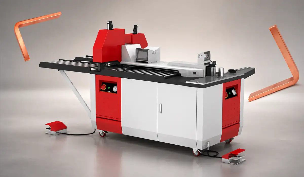
In practice, achieving accurate sizing and installation also depends on consistent production quality from advanced copper busbar processing machine used during fabrication.
| Description | Type |
|---|---|
| Stacked copper foils; low inductance; compact flat profile; ideal for power electronics and battery interconnects | Laminated Busbar |
| Woven copper strands; absorbs vibration and movement; suited for traction and thermal-cycling applications | Braided Busbar |
| Fixed copper or aluminum bar; best for stable, high-current runs; poor mechanical flexibility | Rigid Busbar |
| Multiple round conductors; flexible and easy to source; higher inductance and space requirements | Cable Bundle |
| Pre-terminated flexible busbar with forged ends; speeds assembly and ensures consistent connection quality | Pre-Assembled Flexibar |
Verifying with Vendor Tables & Tests
Use the table above for concept design, then verify against the specific manufacturer’s data before you issue drawings. Flexible busbar ampacity varies more between brands than rigid bar does, because insulation class, lamination thickness, and plating all differ.
Ask every vendor these four questions:
- At what temperature rise and ambient is the rating stated?
- Is the figure for a single bar in free air, or does it assume a mounting condition?
- What is the insulation temperature class, and does it cap the rating before the copper does?
- Is there a type test report, and does it cover the termination as well as the conductor?
Standards & Compliance (IEC 61439, UL 508A)
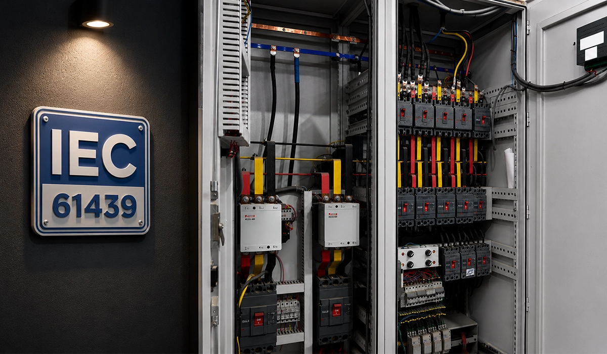
Compliance with major standards like IEC 61439 busbar requirements for low-voltage assembly and UL 508A busbar spacing and SCCR for industrial control panels isn’t optional if you’re building certified equipment. IEC 61439 focuses on construction and performance verification for assemblies — including clearances, creepage distances, and temperature rise—and provides methods to verify short-circuit withstand strength. On the North American side, UL 508A covers industrial control panels and includes an Appendix D that clarifies how busbar systems can be sized and tested for short-circuit current rating (SCCR). For more detail on UL 508A Appendix D, see UL 508A Appendix D – Bus Bar System.
Creepage, Clearance & Insulation
Within those standards, attention to creepage and clearance distances is crucial. These are often dictated by voltage class, pollution degree, and insulation materials. Always verify that your flexible busbar insulation and spacing comply with the applicable tables in IEC or UL guidance documents to maintain safety margins.
Installation & Safety Best Practices
Good installation can be the difference between a flexible busbar that lives long and one that fails early. Consider layout early in your panel design so that the busbar doesn’t have to twist excessively. Respect the minimum bend radius recommended by the manufacturer and use strain relief clamps where needed. Plan routes to minimize loop area and keep parallel runs tidy. Torque all connections to spec so you don’t get loose terminations that heat up. Label connections and document layout for future service. In vibration-prone environments, add mechanical support and verify that insulation isn’t abraded by sharp edges.
Maintenance & Reliability
Periodic checks such as thermal imaging can help catch hot spots before they become failures. Inspect insulation for damage and verify fastener torque over time. Braided flexibility helps absorb vibration, but connectors still benefit from occasional review.
Choosing a Flexible Busbar Manufacturer: Cost, Lead Time, and Make-vs-Buy
When you are comparing flexible busbar manufacturers, price per meter is the least useful number on the quote. Compare these instead:
| What to ask for | Why it separates good suppliers from cheap ones |
|---|---|
| Type test reports | Confirms the rating was measured, not calculated from a formula |
| Stated temperature rise and ambient | Two vendors quoting “600 A” may be using different conditions |
| Insulation class certificate | Determines the real ceiling on the current rating |
| Termination method | Forged and diffusion-welded ends are not the same as a crimp |
| Plating specification | Bare, tinned, or silver changes joint stability over 20 years |
| Minimum bend radius data | Its absence usually means the product has not been characterized |
| Pre-cut and labelled supply | Cuts assembly time and eliminates the commonest site error |
| Lead time on custom lengths | Standard stock lengths ship fast; custom forming does not |
On make-vs-buy: buying pre-terminated makes sense for repeat builds, for high-current joints where a forged or welded end is required, and wherever traceability matters. In-house fabrication makes sense for one-off lengths, for rigid bar work you are already tooled for, and where lead time is the binding constraint.
The existing link to copper busbar processing machine belongs here, in the make-vs-buy discussion — not in the sizing section where it currently sits.
Conclusion: Flexible Busbar
Flexible busbars are a versatile answer to the challenges of modern power distribution. Whether you’re dealing with tight spaces, high vibration, or complex electrical layouts, flexible copper busbar options — from laminated low-inductance designs to braided connectors that handle movement — bring solutions that cables and rigid bars struggle with. Choosing the right flexible busbar means matching current needs, layout constraints, and installation practices while aligning with standards like IEC 61439 and UL 508A to ensure safety and performance.
A thoughtful approach to sizing — using vendor ampacity guidance and accounting for temperature rise — paired with good installation habits, helps your system operate reliably over its service life. Flexible busbars not only reduce assembly time and clutter, they can also boost electrical performance and make future maintenance easier. When you design with both electrical and mechanical factors in mind, you’ll end up with a distribution system that’s efficient, safe, and ready to adapt to tomorrow’s needs.


Rate this article
Choose a rating from 1 to 5 stars.
No ratings yet