








For your convenience, if you prefer listening, you can listen to the rest of this article via the audio file below.
Busbar Support Materials: Epoxy, Polyamide, and GFRP
A procurement engineer picks a low-cost polyester support block for a 1000 A three-phase assembly running in an enclosure that reaches 55 °C. Six months on, the blocks show surface crazing and reduced creepage. The base material has degraded thermally. That degradation matters because a support insulator losing surface integrity loses effective creepage distance between phases and between phase and earth. Once creepage drops below the threshold for the rated voltage, the insulator no longer satisfies IEC 60664-1, a safety exposure and an audit finding at once. Matching busbar supports clamps insulation to operating temperature, voltage, and enclosure environment at the design stage removes the failure mode.
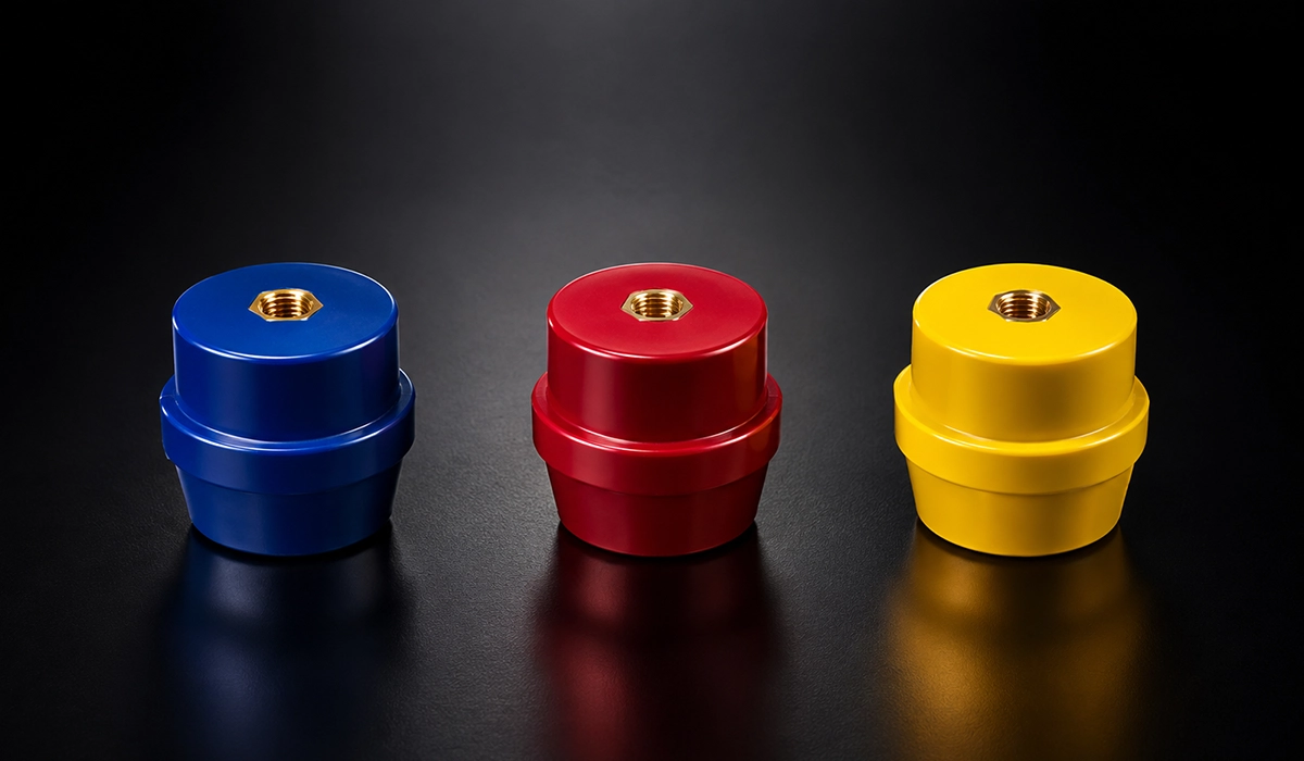
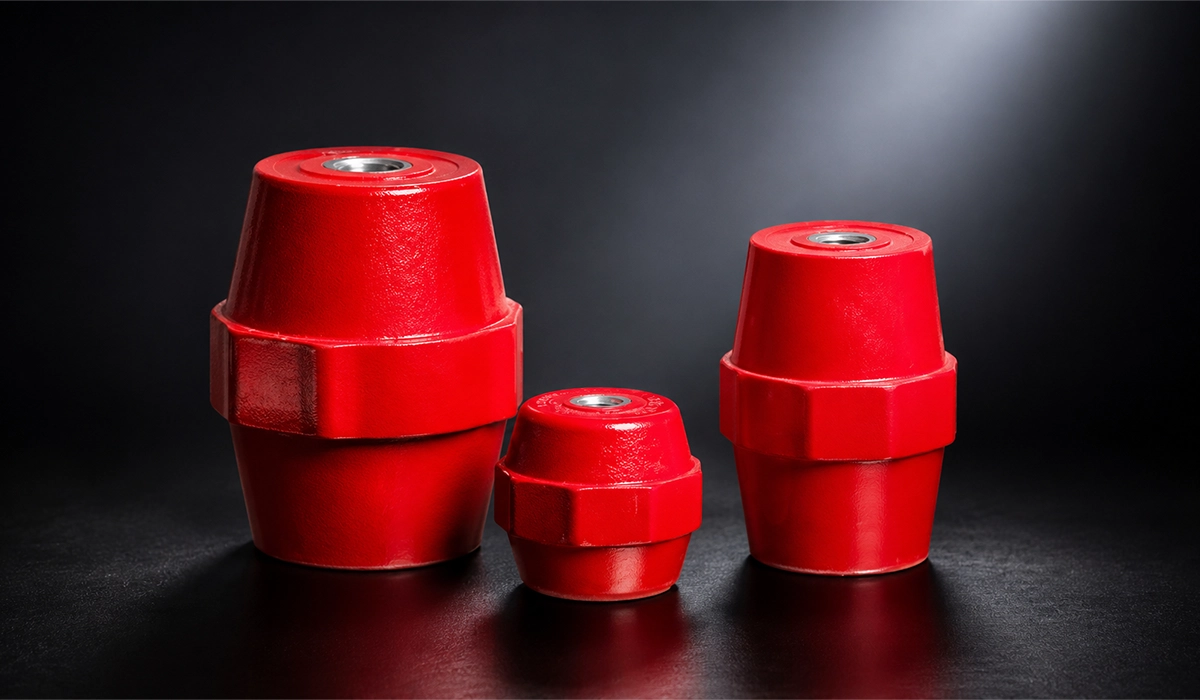
Three materials dominate the busbar support insulators switchgear designers rely on for LV work. Epoxy resin moulded insulators carry high dielectric strength, typically 15–20 kV/mm, hold dimensional stability at elevated temperature, and reach a CTI of 600 or more in high-grade formulations. Epoxy resin busbar supports are the standard choice for main busbar runs up to 1000 V. Polyamide PA66 costs less and offers good mechanical strength with adequate dielectric performance to 690 V, but its CTI runs 175–400 by grade and its continuous limit sits near 105 °C, ruling it out of sustained high-temperature duty. Glass-fibre reinforced polyester provides high mechanical strength and good tracking resistance, earning its place where impact and vibration loads are significant. Selection should be driven by the enclosure temperature class and the rated voltage rather than by unit price.
Support material selection is really one part of a much larger set of decisions about how busbars are specified and deployed across a distribution system. For a broader look at busbar types, sizing, and typical applications, see this guide to power distribution busbars.
| Material | Dielectric Strength | CTI (Typical) | Max Continuous Temp | Common Application |
|---|---|---|---|---|
| Epoxy Resin | 15–20 kV/mm | 400–600+ | 130–155 °C | Main Busbars, HV-Adjacent LV |
| Polyamide PA66 | 14–17 kV/mm | 175–400 | 95–105 °C | General LV Panel Supports |
| GFRP (Polyester) | 12–16 kV/mm | 150–250 | 130 °C | High-Vibration / Impact Duty |
| Polycarbonate (PC) | 15–18 kV/mm | 250–375 | 115–120 °C | Phase Barriers, Finger Guards |
Indicative property values — verify against the manufacturer datasheet for the specific grade. Based on IEC 60112, IEC 60893-3, and general industry data.
Download this resource to compare the details more easily during your review process.
Comparative Tracking Index and Its Role in Insulator Selection
CTI measures a material’s resistance to surface tracking, the formation of conductive carbonised paths under combined electrical stress and contamination. Under IEC 60112, a voltage is applied between two electrodes on the material surface in the presence of an electrolyte, and the CTI is the highest voltage at which no tracking occurs over 50 drops. The result places the material in a group that sets the minimum busbar insulator creepage distance: I at CTI ≥ 600, II at 400–599, IIIa at 175–399, and IIIb at 100–174. These groups feed directly into IEC 60664-1, which sets minimum creepage distance by group and rated voltage. A higher CTI permits a shorter creepage distance for the same voltage class.
You can download the supporting document here and use it during your project planning.
Thermal Class of Insulation: What It Means for Busbar Design
What is the thermal class of busbar insulation for high-current applications comes down to three bands. Solid insulation carries a thermal class: Class B at 130 °C, Class F at 155 °C, Class H at 180 °C. The support insulator must hold a thermal class equal to or above the maximum temperature at the conductor surface under rated load, including the ambient contribution. IEC 61439-1 limits conductor temperature rise to 70 K above a 40 °C reference ambient for most assembly categories, which puts the maximum conductor surface temperature near 110 °C. That sits inside the Class B range for most continuous-duty designs. High cyclic loading or reduced ventilation, which raise the surface temperature further, may push the requirement to Class F material.
Further exploration of what is busbar can be found in the following recommended reading.
Busbar Support Spacing: Mechanical and Short-Circuit Considerations
An engineer runs a horizontal three-phase busbar at 2500 A on 100 × 10 mm copper, supports at 600 mm centres, downstream of a transformer with 50 kA prospective short-circuit current. During a fault, a support fractures. The electromagnetic force at that span exceeded the mechanical rating of the support. The consequence is severe: a fractured support lets the busbar deflect into an adjacent phase or into the earthed enclosure, converting a controlled fault clearance into a phase-to-phase or phase-to-earth arc flash, destroying the assembly and endangering anyone nearby. This is why busbar support spacing calculation for busbar supports clamps insulation must work against the peak electromagnetic force of a short-circuit event, not merely the static weight of the bar.
Two loads set the spacing. The static load is the weight of the busbar and any connected cable, producing a bending moment across the span that follows the simple beam relation, maximum bending moment = wL²/8 for a uniformly distributed load between two supports. The dynamic load is the electromagnetic force between adjacent phases during a fault, from F/L = (µ₀/2π) × (I²/d), where I is the peak fault current and d is the phase spacing. The support insulator must carry the combined bending force from both without fracture or permanent deformation. Knowing how to calculate busbar support spacing for short-circuit forces comes down to this comparison; the table gives worked values for common sizes and fault levels, and the caption on the peak-current basis materially affects the numbers.
Spacing is only correctly set once it has been checked against the full short-circuit withstand requirement of the assembly, not just the static load case. For calculation approaches and rated withstand values, see this guide to short-circuit withstand.
| Fault Current (kA Rms) | Phase Spacing d (mm) | Peak Force F/L (N/m) | Typical Max Span (mm) |
|---|---|---|---|
| 25 | 60 | 13,000 | 400–500 |
| 25 | 100 | 7,800 | 500–600 |
| 50 | 60 | 52,100 | 250–350 |
| 50 | 100 | 31,300 | 350–450 |
| 65 | 100 | 52,800 | 250–350 |
Peak electromagnetic force per metre between adjacent phases during a fault, from F/L = (µ₀/2π) × (I²_peak/d) with I_peak = 2.5 × I_rms. Based on IEC 62271-200 and CDA Publication 22. Values recomputed directly from the formula; confirm the peak-to-rms factor against the actual fault asymmetry for the installation.
Busbar Deflection Under Self-Weight: Sag Limits
A horizontal busbar sags under its own weight between supports. For flat copper bars mounted on edge, the orientation preferred for cooling, the sag depends on the second moment of area in the bending direction. The maximum deflection of a simply supported beam is δ_max = 5wL⁴ / (384EI). Here w is the load per unit length, L is the span between supports, E is Young’s modulus for copper at roughly 117 GPa, and I is the second moment of area, which describes how the cross-section resists bending. A commonly applied limit is a maximum sag of L/300. Because deflection rises with the fourth power of span, halving the support distance cuts the sag dramatically, which is often the simplest fix for a run that fails the limit.
Clamp and Saddle Types: Selection for Different Busbar Geometries
A panel builder mounts flat copper bars flat on saddle clamps that grip by friction alone. Vibration from an adjacent motor starter lets them shift sideways, and within six months they migrate enough to drop the phase-to-phase clearance below the IEC 60664-1 minimum. Reduced air clearance compromises insulation coordination across the assembly, demanding physical correction and re-verification. Knowing how to prevent busbar vibration in switchgear enclosures comes down to clamp choice: matching geometry to orientation, and specifying positive lateral retention over friction grip, holds the phase spacing for the assembly’s life. This also answers how to select busbar clamps for flat copper busbars in LV panels.
The busbar clamp types for panel building cover several geometries. The saddle clamp retains the bar from below and both sides and is the commonest fitting in distribution boards. The channel or multibar holder is a moulded block with slots at a set phase spacing that fixes centre-to-centre distance. The end clamp fixes the bar against longitudinal movement at the run’s end. The spring clamp allows controlled movement in long runs while holding the bar laterally, acting as a busbar vibration isolation support where a starter or drive introduces excitation. Orientation drives busbar mounting hardware selection: an edge-mounted long run suits a spring saddle, a flat short run a simple one. At PAYAPRESS, flat copper busbars are supplied to the dimensional tolerances required by the panel builder’s chosen support and clamp system, with hole patterns drilled to the centre-to-centre spacing of the specified support block.
Clamp geometry only makes sense in the context of the busbar layout it’s holding in place. This guide to LV panel busbars covers those layout considerations in more depth.
| Support Type | Busbar Orientation | Lateral Retention | Longitudinal Control | Typical Use |
|---|---|---|---|---|
| Saddle Clamp | Flat or Edge | Friction | None | General LV Distribution Boards |
| Channel / Multibar Holder | Flat or Edge | Positive (Slotted) | None | Main Busbar Runs, MCCs |
| End Clamp / End Stop | Either | Positive | Fixed | End of Busbar Run |
| Spring Saddle | Edge | Positive | Sliding (Controlled) | Long Busbar Runs, Thermal Expansion |
| Through-Bolt Insulator | Either | Positive | Fixed | High Short-Circuit Duty |
Support type selection by application and busbar orientation. Based on CDA Publication 22 and general panel building practice.
Busbar Insulation: Heat Shrink, Tape, and Phase Barriers
A panel for an IP54 enclosure uses bare copper bars with air insulation between phases. Clearances pass on the drawing, but the enclosure fails the dust ingress test: dust on the bars reduces effective creepage below the design value and undermines insulation coordination. Bare copper in a contaminated or humid environment accumulates deposits that erode air insulation. The difference between heat shrink insulation and epoxy busbar insulator is functional: applied insulation holds dielectric performance regardless of contamination, whereas the support carries mechanical load. Matching applied insulation to voltage, temperature class, and exposure removes the degradation mechanism and eases IP compliance.
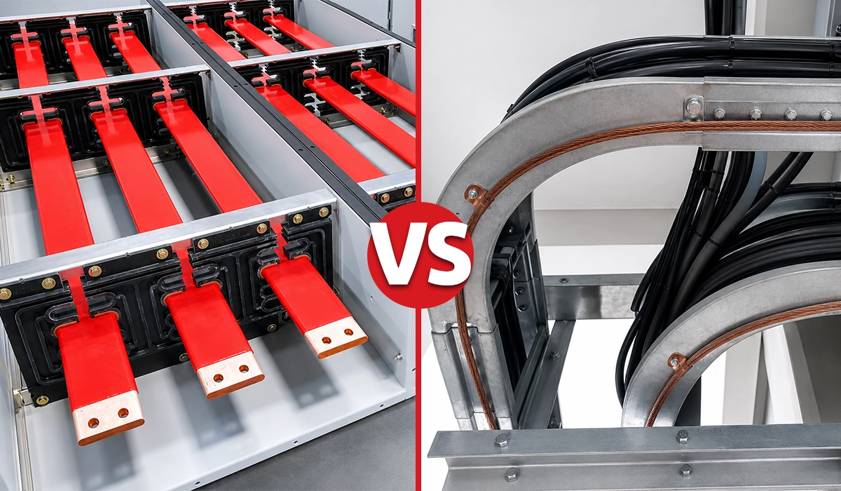
Three applied busbar insulation materials LV panels rely on cover the field, complementary rather than alternative. Heat shrink tubing, polyolefin or cross-linked polyolefin, is applied over the bar with a hot air gun. It comes in the standard IEC 60446 phase colours of brown, black, grey, and blue, carries 20–30 kV/mm in cross-linked grades, and operates from −55 °C to +125 °C. Overlap at joints and supports is essential to continuous coverage. Self-amalgamating or PVC tape handles localised insulation at joints and bends; its lower dielectric strength makes it supplementary. Phase barrier panels, moulded polycarbonate or GFRP fitted between phases, give phase-to-phase insulation independent of air clearance and contribute to the form of separation under IEC 61439. A complete insulated busbar system enclosure design uses all three together, and within a busbar supports clamps insulation package the busbar insulation sleeve heat shrink layer is usually primary.
Applied insulation choices work together with how the busbar itself is positioned and mounted inside the enclosure. For more on that integration, see this guide to busbars in panels.
| Insulation Method | Dielectric Strength | Temp Range | Phase Colour Available | Primary Use |
|---|---|---|---|---|
| Cross-Linked Polyolefin HS | 20–30 kV/mm | −55 °C to +125 °C | Yes (IEC 60446) | Full Bar Coverage, Contaminated Env. |
| Standard Polyolefin HS | 15–20 kV/mm | −55 °C to +90 °C | Yes | General LV Panel Busbars |
| Self-Amalgamating Tape | 20–26 kV/mm | −40 °C to +90 °C | Limited | Joint Insulation, Bends |
| PVC Insulating Tape | 8–12 kV/mm | 0 °C to +70 °C | Yes | Supplementary / Temporary |
| Phase Barrier (PC / GFRP) | 15–18 kV/mm | Up to 130 °C | N/A (Fixed Colour) | Phase Separation in Busbar Chamber |
Indicative properties — verify against product datasheet. Based on IEC 60684-3, IEC 60446, and general industry data.
You can explore this trusted source for more complete and updated information.
Phase Colour Coding to IEC 60446
IEC 60446 assigns AC conductor colours as L1 brown, L2 black, L3 grey, neutral blue, and protective earth green-yellow. These replaced the legacy red, yellow, and blue phase colours, a transition complete across IEC-jurisdiction countries since around 2004. North America follows a different convention, black, red, and blue for the three phases, which does not apply under IEC 61439 or the AS/NZS framework. For a bare copper busbar, heat shrink tubing in the correct phase colours is the most reliable way to apply and maintain identification across the full length of the bar, which is why busbar insulation colour coding IEC standard practice leans on coloured sleeving rather than paint or tape.
Insulation Contribution to IP Degree of Protection
Applied busbar insulation can contribute to the IP rating of an assembly by reducing the chance that a test probe reaches a live conductor through a gap in the enclosure. IEC 60529 assesses the complete assembly, not the enclosure shell in isolation, so the state of the busbars matters to the result. The point on how does busbar insulation contribute to IP degree of protection needs a clear boundary, though: heat shrink does not by itself confer an IP rating on the bar, and the enclosure must still pass the IEC 60529 tests on its own terms. What insulated busbars do is reduce the risk of an IP failure at joints and support apertures, where a probe might otherwise find a live surface.
Integrating Supports, Clamps, and Insulation into the Design Verification Record
A builder finishes a 3200 A main distribution board using epoxy insulators, multibar holders, and heat shrink insulated bars. When the customer requests the IEC 61439 technical file, the builder has no insulator datasheets and no record of the spacing calculation. Without documented evidence that the support material meets the thermal and CTI requirements for the rated voltage, and that spacing was calculated against the prospective short-circuit current, the record is incomplete and the panel cannot be declared compliant under the verified design route. Treating support, clamp, and insulation selection as a documented engineering decision closes the section of the technical file most often found wanting.
Four items and two calculations complete the record. The first is a material datasheet per insulator type, confirming CTI group, thermal class, and dielectric strength. The second is the spacing calculation, showing the electromagnetic force at the prospective short-circuit current against the support’s mechanical rating. The third is a creepage verification, confirming the support geometry meets IEC 60664-1 for the rated voltage and CTI group. The fourth is an insulation system description: heat shrink or barrier type, dielectric strength, and temperature rating relative to the busbar operating temperature. This is not onerous, amounting for a standard design to four datasheets and two calculation sheets, yet it is a frequent finding in third-party IEC 61439 audits. PAYAPRESS supports this documentation requirement by supplying fabricated busbar assemblies with dimensional records and material traceability that integrate directly into the panel builder’s IEC 61439 design verification file.
Much of this documentation and calculation burden can be reduced with the right tools built for the task. See this overview of busbar design software for tools that support these calculations.
| Document Required | Content | Retained In |
|---|---|---|
| Insulator Material Datasheet | CTI Group, Thermal Class, Dielectric Strength | Design File |
| Support Spacing Calculation | Fault Current, Phase Spacing, Force, Span | Design File |
| Creepage Distance Verification | Rated Voltage, CTI Group, Required vs Actual | Design File |
| Insulation System Datasheet | Type, Dielectric Strength, Temperature Class | Design File |
| Phase Colour Confirmation | IEC 60446 Colour Assignment Documented | Assembly Record |
| Supplier Material Certificate | Material Grade and Lot Traceability | Quality File |
Documentation requirements for busbar supports and insulation under IEC 61439-1:2020 Clauses 6 and 10.
Conclusion about Busbar Supports
Supports, clamps, and insulation serve three integrated functions in a busbar assembly. The mechanical function holds the conductors in position under both static weight and fault-current electromagnetic loads. The electrical function maintains the designed creepage and clearance distances across the service life of the assembly. The environmental function protects the insulation system from contamination, humidity, and thermal degradation. Under the IEC 61439 verified design route, each of these must be documented in the technical file rather than assumed from good practice, which means datasheets, a spacing calculation, and a creepage verification retained in the design record. Specified correctly and evidenced properly, a busbar supports clamps insulation system lowers long-term maintenance cost and reduces the risk of thermal and mechanical fault incidents over the life of the panel.
For a complete walkthrough of selecting the right busbar system from the ground up, see this busbar selection guide.


Rate this article
Choose a rating from 1 to 5 stars.
No ratings yet