


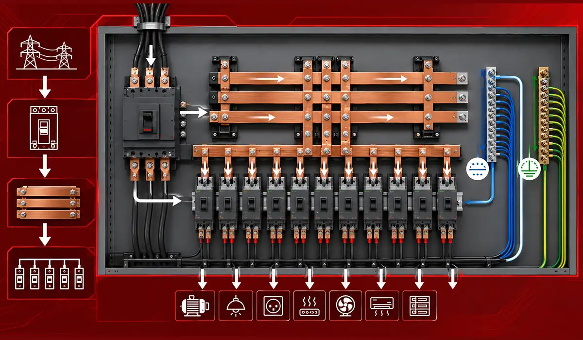
How a Busbar Distributes Power Inside a Panel
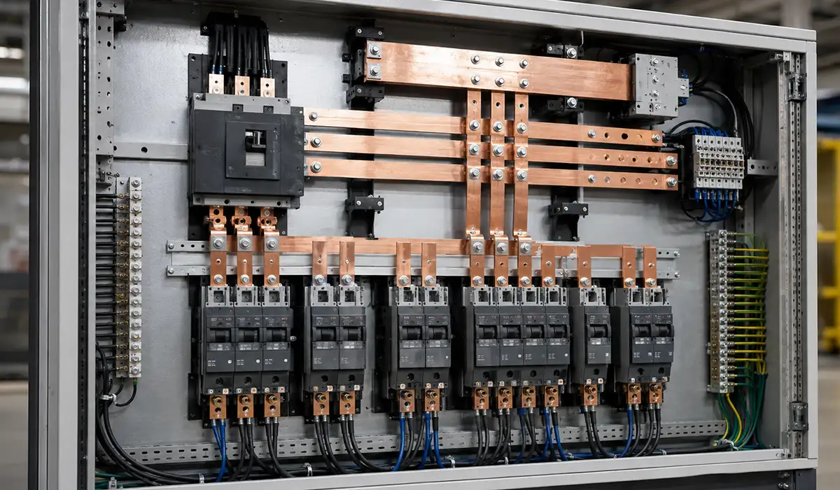
Follow the current through a typical assembly and the role becomes obvious. Power arrives at the incoming device, lands on the main phase busbars, and from there feeds every outgoing breaker that clips or bolts onto those bars. Return current collects on the neutral bar. Fault current takes the earth bar back to the bonding point. One incoming connection, one shared conductor, many outgoing circuits.
That is also why busbars scale where cable does not. A cable serves one circuit; adding a circuit means adding a cable. A busbar can be tapped at almost any point along its length without creating a new joint upstream, so adding a breaker is a change to the panel, not a change to the feeder.
A busbar is a metallic conductor—usually a flat bar, though it may also be round, tubular, or laminated—used as a shared electrical bus inside an assembly. In simple terms, it is a conducting bar that receives power at one point and makes that power available to several circuits or devices.
Learn more about busbar fundamentals here.
“Bus Bar in Electrical Panel” Can Mean Three Different Things
Ask three people what the bus bar in an electrical panel is and you may get three correct but different answers. The term covers several components that do very different jobs, and knowing which one you are looking at changes everything that follows.
| Main / Phase Busbars | Neutral Bar | Ground (Earth) Bar | |
|---|---|---|---|
| What It Does | Carries Phase Current From the Incomer to Every Outgoing Device | Collects Return Current From the Loads | Provides the Protective Bonding Path for Fault Current |
| What It Looks Like | Heavy Flat Copper or Aluminum Bars, Often Three or Four in Parallel | A Drilled Strip With Many Small Terminal Screws | A Similar Strip, Usually Smaller, Bolted to the Enclosure |
| Where You Find It | Switchboards, MCCs, Distribution Boards, Load Centers | Every Panel | Every Panel |
| Carries Current Normally? | Yes, Continuously | Yes | No — Only During a Fault |
| Typical Rating | 100 A to 6300 A | Matched to Phase, Sometimes Larger | Sized to Fault Duty, Not Load |
There is a fourth thing people mean, especially in North America. In a residential or light-commercial load center, the main busbars are not visible bars at all — they are stamped copper or aluminum strips with stabs (also called fingers or jaws) that breakers clip onto directly. Same principle, different packaging: one shared conductor feeding many outgoing devices without individual cable runs.
The question people most often mean. If you are looking at a panel and wondering whether neutrals and grounds can share a bar, the answer depends on which panel it is. In a service or main panel, where the main bonding jumper connects neutral to the enclosure, the two are already bonded, so landing both on the same bar is generally permitted. In a sub-panel, they must stay separate: the neutral bar is isolated from the enclosure on insulating standoffs, and the ground bar bolts directly to it. Mixing them in a sub-panel puts normal return current onto the equipment grounding path.
That distinction is why panels ship with bars that look interchangeable but are not. A supplementary bar sold as a neutral bar comes with isolating hardware; a bar sold for grounding is designed to contact the enclosure and is usually marked as unsuitable for neutrals.
If this is your own home panel, confirm the arrangement with a licensed electrician and your local authority before changing anything. Codes differ by jurisdiction and by panel listing.
The rest of this article covers the main phase busbars in low-voltage panels and switchgear — how they are selected, sized, fabricated and verified.
What a Bus Bar Actually Does in an Electrical Panel
The core busbar function in switchgear is not just to carry current. It also improves layout discipline, simplifies assembly, and supports predictable fault performance in the electrical panel busbar system. In a busbar in distribution board arrangement, the designer is balancing current flow, thermal rise, access, and future expansion.
Explore the full power distribution applications for more details.
- Distributes power from the main incomer to branch circuits with fewer interconnections.
- Cuts wiring complexity and frees usable panel space for breakers, metering, and accessories.
- Provides a low-impedance path that helps the assembly manage fault current.
- Separates phase, neutral, and protective earth functions for safer maintenance and clearer design intent.
Because the busbar is rigid and centralized, additions and modifications are often cleaner than with dense cable looms. That matters in switchgear and controlgear busbar layouts where downtime, retrofit speed, and inspection quality all have real cost. For a deeper look at low-voltage distribution practices, the Schneider Electric Installation Guide offers detailed IEC-based design recommendations.
Notice what these have in common. Only the first is about carrying current. The other three are about the panel as a system — space, fault behaviour, and maintainability. That is the honest case for busbars: they rarely win on conductivity alone, they win on everything that surrounds the conductor.
Main Busbar vs Neutral Bar vs Earth Bar: How They Differ
The main busbar carries phase power to the outgoing functional units. The neutral bar carries return current, and the earth bar provides the protective bonding path that supports fault clearing and touch-voltage control. Keeping those bars distinct is basic good practice, whether the project follows IEC assemblies or NEC panel rules.
See our ground bus bar guide for protective bonding details.
In larger assemblies, the PE bar is bonded to the frame, while neutral sizing may be increased where unbalance or harmonics are expected. That distinction is one reason a circuit breaker panel busbar layout is safer and easier to service than improvised mixed conductor routing.
One practical consequence is worth stating plainly. The earth bar carries no current in normal operation, so it is not sized by load — it is sized by the fault current it must survive for the time the protective device takes to clear. A bar that looks generously sized for everyday duty can still be wrong for fault duty, and the two calculations are unrelated.
Why Busbars Distribute Current More Efficiently Than Cable
A well-designed busbar arrangement improves current sharing because the current distribution bar has a known geometry, short path length, and fewer terminations. In high-current panels, that helps reduce voltage drop, lowers resistive loss, and supports more stable operating conditions than crowded multi-cable wiring.
This does not mean busbars are always better than cables in every case. It means that for compact, high-current, expandable assemblies, busbars usually deliver the cleaner electrical path and the more predictable thermal result. Improving system efficiency also depends on power factor correction across the installation.
Types of Busbar and Busbar Panel Formats
When people ask about types of busbar in electrical panels, they usually mean both shape and system architecture. Common choices include flat strip bars, tubular bars, insulated comb-style bars, and prefabricated busbar trunking or sandwich systems for higher current or faster installation.
Selection depends on current rating, available space, short-circuit duty, mounting method, and whether the assembly is a compact panelboard, an MCC, or a large switchgear lineup. Flat versus tubular and insulated versus bare are not cosmetic choices; they change cooling, rigidity, clearance, and fault performance. For tight-bend routing needs, review flexible busbar types available today.
| Format | Typical Current Band | Where It Is Used | Trade-Off |
|---|---|---|---|
| Flat Strip Bar | 100–4000 A | Panelboards, MCCs, Switchboards | Cheapest and Simplest; Needs More Space at High Current |
| Multiple Parallel Bars | 2000–6300 A | Main Switchboards, Incomer Sections | High Capacity; Spacing and Clamping Become Critical |
| Tubular Bar | 1000 A+ | Outdoor Switchyards, HV | Excellent Stiffness and Cooling; Costly, Harder to Fabricate |
| Insulated Comb Bar | 63–160 A | Final Distribution, DIN Rail Devices | Fast, Tidy, No Fabrication; Fixed Pitch Limits Layout |
| Busbar Trunking (Busway) | 160–5000 A | Risers, Factory Floor Distribution | Tap-Off Anywhere; Higher First Cost |
| Sandwich / Laminated Bar | 800–6300 A | Data Centers, Compact High-Current Runs | Very Low Impedance, Compact; Least Field-Modifiable |
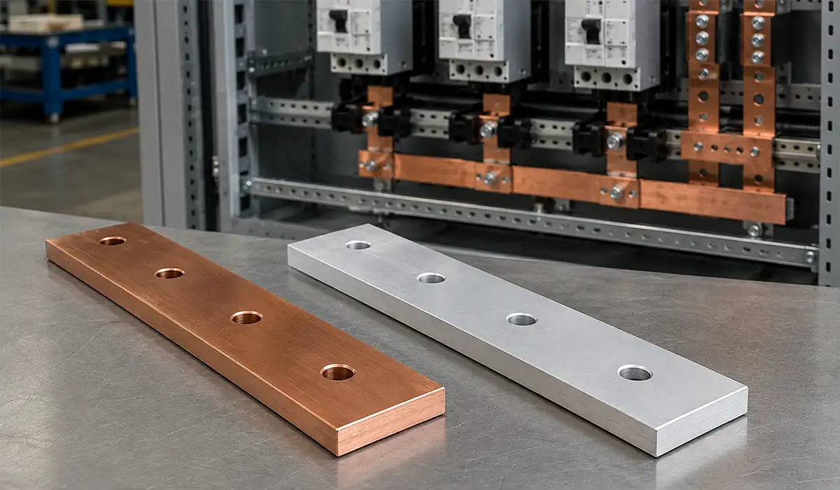
Copper vs Aluminum Busbars: Which to Specify
The most common materials are copper and aluminum, and the choice is usually a reliability-versus-economy decision rather than a right-versus-wrong one. Copper gives higher conductivity and typically allows a smaller section for the same duty, while aluminum lowers weight and first cost.
| Parameter | Copper Busbar | Aluminum Busbar |
|---|---|---|
| Raw material cost (relative) | 100% baseline | ~30–40% of copper |
| Required cross-section for same duty | Baseline | ~1.6× larger |
| Weight for same duty | Heavier | ~50% lighter |
| Net material cost for equivalent rating | Baseline | ~50–65% of copper |
| Joint hardware complexity | Lower | Higher |
| Maintenance burden | Lower | Higher |
Copper is often preferred in high-reliability assemblies, dense switchgear, and projects where connection stability, compact size, and corrosion performance matter most. That is why the phrase copper busbar electrical panel appears so often in specifications for critical infrastructure. For DC-system jointing, see the Victron busbar overview.
Aluminum is still widely used, especially in busbar trunking system products and large distribution runs where weight and cost are important. The trade-off is that joints, contact surfaces, and protective treatments deserve more attention than in a comparable copper design.
So the real question is not copper or aluminum in isolation. It is copper vs aluminum under the project’s current, space, maintenance, and life-cycle cost constraints. For comprehensive material-selection criteria,
the Copper for Busbars design guide covers conductor sizing, joint preparation, and surface treatment in depth.
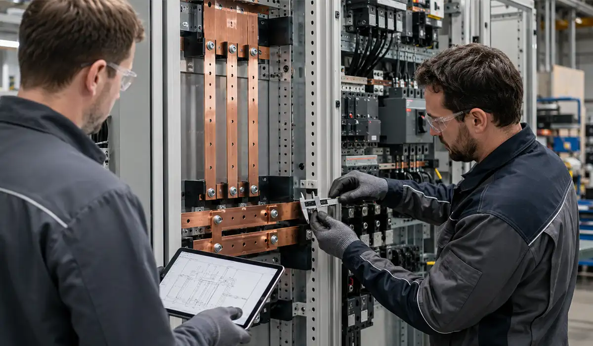
How Busbar Size Is Determined for a Panel
Busbar sizing for electrical panel design starts with load current, but it cannot stop there. The designer must consider continuous current, peak current, ambient temperature, enclosure ventilation, permissible temperature rise, and the assembly’s required short-circuit withstand rating. Our complete busbar sizing guide walks through the calculation steps.
At higher frequencies—or where harmonics are significant—skin effect and proximity effect can increase effective resistance and heating. That matters less in a simple 50/60 Hz feeder than in compact, high-current layouts with thick conductors and distorted waveforms.
Translating those sizing decisions into physical bars with accurate holes and clean edges requires reliable busbar fabrication and processing systems that maintain tolerance across every piece.
A useful first-pass rule is: Required area ≈ design current / allowable current density. After that, the designer validates the choice against ampacity tables, temperature-rise limits, fault duty, and joint performance. Busbar current carrying capacity is therefore a thermal and mechanical decision, not only a cross-sectional one. Engineers can speed up calculations with busbar design software tools.
As a practical example, a 1600 A main distribution board feeding an MCC may need multiple parallel copper bars per phase, not because the arithmetic current says so alone, but because clearance, short-circuit force, and heat rise all push the final selection upward. For detailed engineering formulas and skin-effect calculations, the Mersen busbar design guide provides a thorough technical reference.
Busbar vs Cable Wiring: Why Panels Choose Busbars
The reason designers compare busbar vs cable wiring is simple: both can move power, but they behave differently in compact assemblies. The use of busbar in electrical panels becomes especially attractive when current is high, space is tight, and future circuit changes are expected.
Compared with large cable bundles, busbars usually save space, improve airflow, and make fault paths easier to model. They also reduce the number of lugs, bends, and terminations, which helps installation quality and speeds maintenance in an electrical panel busbar system. Clean field terminations rely on a proper terminal bus bar arrangement.
At scale, busbars can also lower labor hours because the installer is fitting a structured system instead of routing and dressing many heavy conductors. In expandable facilities, tap-off or modular bus systems make later additions cleaner than reworking a dense cable loom.
Cables still make sense for flexible runs, smaller currents, and irregular geometries. But in switchboards, MCCs, and high-current distribution sections, busbar often wins on orderliness, heat dissipation, and maintainability.
Busbar Standards: IEC 61439, NEC 408 and BS 7671
Busbar assemblies inside panels are not designed in a standards vacuum. IEC 61439 governs low-voltage switchgear and controlgear assemblies, including construction and verification requirements, while NEC Article 408 addresses switchboards, switchgear, and panelboards in U.S.-style practice.
Short-circuit current rating is one of the biggest safety issues. In NEC-based installations, the equipment rating must not be lower than the available fault current. In IEC-based practice, the assembly also has to satisfy design verification requirements rather than rely on guesswork.
BS 7671 adds installation-side expectations for current-carrying capacity, voltage drop, and secure terminations, including busbar-related checks and appendices that support busbar trunking design decisions. This is where IEC vs NEC becomes a documentation difference, not a reason to relax engineering discipline.
For that reason, good busbar design is never just about conductivity. It is about compliance, verification, labeling, terminations, and fault withstand as a complete assembly. Full code text and updates are available through the NFPA 70 National Electrical Code for U.S.-based projects.
Where Busbars Are Used: From Load Centers to MCCs
Busbars are common in main distribution boards, sub-distribution boards, motor control centers, industrial switchgear, and data center distribution paths. In these applications, the value is not only ampacity but also compact routing, orderly expansion, and repeatable connection quality. Compare different distribution board types before specifying.
Manufacturer application data shows how different systems serve different duties: lighter systems for 40–160 A branch distribution, medium systems up to 1250 A, and larger sandwich or ventilated systems for 5000 A or more. That range explains how does a busbar work in a distribution board and why the same idea scales into heavy industry.
A practical example is a factory with one transformer feeding an MDB, then several MCC sections and process lines. Using busbars between the transformer, main infeed, and high-load sections simplifies layout and makes later capacity changes easier than re-pulling large cable sets. Stay ahead by reviewing future busbar trends shaping the industry.
Conclusion: The Strategic Role of Busbars in Electrical Panels
The use of busbar in electrical panels comes down to performance, order, and safety. A good busbar layout distributes power efficiently, supports fault duty, reduces wiring clutter, and makes the assembly easier to inspect and expand. That is why busbars remain standard in switchboards, MCCs, distribution boards, and modern infrastructure projects.
If the decision is still open on a real project, compare copper vs aluminum, busbar vs cable, flat vs sandwich, and IEC vs NEC documentation requirements before freezing the design. That comparison will usually reveal the right solution faster than debating material or format in isolation.