








Prefer listening? You can play the audio version of the rest of this article below.
PDB Full Form in Electrical: What the Abbreviation Means
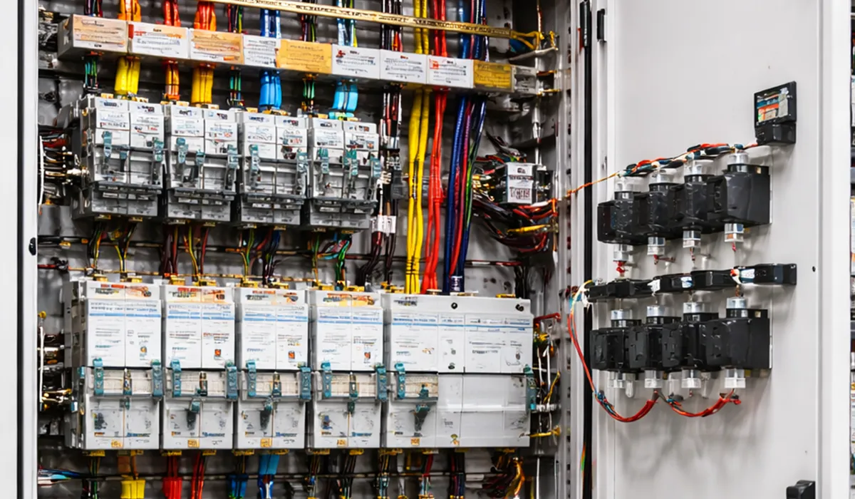
PDB stands for Power Distribution Board. You will also see it written as a power distribution panel (PDP), distribution board (DB), panelboard (North America), or consumer unit (UK domestic).
The terms are not perfectly interchangeable:
- PDB / Power Distribution Board — the general term for any enclosed assembly distributing power to multiple circuits.
- MDB / Main Distribution Board — the first board after the transformer or utility supply.
- SMDB / Sub-Main Distribution Board — an intermediate board fed from the MDB, feeding final boards.
- FDB / Final Distribution Board — the last board in the chain, feeding lighting, sockets and small power directly.
- DBO — the IEC term for a distribution board intended to be operated by ordinary (non-electrician) persons.
In tender documents and single-line diagrams, MDB, SMDB and FDB are the abbreviations you will meet most often.
Which IEC 61439 Standard Applies to Your Board?
This is the first question to settle, because it determines every verification requirement that follows — and the answer depends on who operates the board and how much current it carries.
| Standard | Applies to | Limits | Operated by |
|---|---|---|---|
| IEC 61439-1 | General rules for all LV assemblies | Up to 1000 V AC / 1500 V DC | — |
| IEC 61439-2 | Power switchgear and controlgear assemblies (PSC) | No current limit | Skilled persons |
| IEC 61439-3 | Distribution boards for ordinary persons (DBO) | ≤300 V to earth; ≤125 A per outgoing circuit; ≤250 A assembly | Ordinary persons |
| IEC 61439-5 | Assemblies for public distribution networks | Utility distribution | Skilled persons |
Table 1 — Which part of IEC 61439 governs which board type.
In practice: a domestic consumer unit or a small office final board is a DBO under Part 3. A main LV board in a substation, a motor control centre, or anything above 250 A is a PSC assembly under Part 2. Part 1 always applies underneath either.
One consequence people miss: under Part 3, the incoming device must require a key or tool to reset if it is not itself a device rated for operation by ordinary persons. That is a design constraint, not a preference.
Classification of Power Distribution Boards
Boards are classified in three independent ways — by function in the distribution hierarchy, by mounting, and by internal separation. All three appear in specifications, and confusing them is a common source of ordering errors.
By Function
- Main distribution board (MDB) — installed in the substation, connected to the LV side of the transformer, distributing and controlling the site’s power.
- Sub-main distribution board (SMDB) — an intermediate board serving a building, floor or utility group.
- Final distribution board (FDB) / lighting sub-board — the last board in the chain, feeding lighting, socket and small-power circuits directly.
By Mounting and Access
| Board Type | Mounting | Access | Typical Application |
|---|---|---|---|
| Main Low-Voltage Distribution Board | Floor-standing | Front or rear | Substation — primary power distribution |
| Sub-main Distribution Board | Floor-standing | Front or rear | Facilities and utility sub-feeds |
| Multi-compartment Board | Floor-standing | Front (each cell) | Motor control centres, expandable systems |
| Multi-box Board | Floor or wall | Front plus side boxes | Industrial, dusty or humid areas |
| Sub-distribution Board | Wall (flush or surface) | Front | Lighting, sockets, small power |
| Outdoor Power & Lighting Board | Floor (on platform) | Front only | Street lighting, outdoor substations |
Table 2 — Board types, mounting methods and typical applications.
Internal Separation: Forms 1 to 4b Explained
Internal separation is the classification that most affects safety and price, and the one most often left out of a specification until it is too late to change. It describes how much of the board stays live and exposed when you open it to work on one circuit.
| Form | Separation provided | What it means in practice |
|---|---|---|
| Form 1 | None | Open the door and everything is live and exposed. Isolate the whole board to work on anything. |
| Form 2 | Busbars separated from functional units | The main busbars are shielded, but the outgoing devices are not separated from each other. |
| Form 3 | Busbars separated; functional units separated from each other | You can work on one outgoing way with the others still enclosed. Terminals may still be common. |
| Form 4 | Full separation including terminals | Each functional unit and its terminals are individually enclosed. Highest safety, highest cost and size. |
Table 3 — Internal separation forms under IEC 61439-2.
Forms 3 and 4 subdivide further into a and b variants depending on whether terminals are separated from the busbars and from each other. Form 4b is the most common specification for critical installations — data centres, hospitals, process plants — where circuits must be worked on without shutting the board down.
The trade-off is real: each step up adds barriers, depth and cost. Specify Form 4b for a small office final board and you have paid for containment nobody will use. Specify Form 2 for a hospital main board and maintenance will require a full outage.
Fully Enclosed Floor-Standing Power Distribution Boards
Front-Accessible Board
All operations — fuse replacement, cable terminations, incoming and outgoing connections — are accessible only from the front. A small side door is often provided next to the main door for feeder cable connections. Cells divide into top-entry and bottom-entry types. Front access is the only option when the board sits against a wall.
Rear-Accessible Board
Equipment replacement and cable connections are made from the rear, while measuring instruments and control operations stay on the front face. This gives a shallower front footprint but requires rear clearance, so the board cannot be wall-mounted.
Multi-Compartment Board
Each cell divides into three, four or six main compartments, and each main compartment into two, three or four sub-compartments. All divisions share standard equal dimensions, and each section has its own door for device installation or replacement. This is the physical construction that delivers Form 3 and Form 4 separation.
Multi-Box Board
Equal-dimension boxes in cast iron, steel or moulded material, mechanically connected. Each box carries removable doors with sealing gaskets to prevent dust and water ingress. Preferred for outdoor substations and industrial, dusty or humid areas.
Maximum Dimensions — Main Low-Voltage Floor-Standing Boards
| Dimension | Front-Accessible | Rear-Accessible | Multi-Compartment |
|---|---|---|---|
| Height | 220 cm | 220 cm | 200 cm |
| Width | 90 cm | 90 cm | 50 cm |
| Depth | 60 cm | 80 cm | 50 cm |
Table 4 — Maximum enclosure dimensions for floor-standing boards. These are typical project-specification limits; IEC 61439 sets no dimensional maximum, so confirm against your local code and the assembly manufacturer’s verified design.
Minimum Clearances Around Distribution Boards
A working distance must always be maintained between the wall and the board, and between adjacent boards. The absolute minimum is 70 cm, and the clear space in front of the door must let it open to at least 90°.
| Board 1 face ↓ / Board 2 face → | Front (operational) | Side (serviceable) | Rear (closed) | Wall |
|---|---|---|---|---|
| Front (operational) | 1.2 m | 1.2 m | 1.0 m | 1.0 m |
| Side (serviceable) | 1.2 m | 1.0 m | 0.8 m | 0.8 m |
| Rear (closed) | 1.0 m | 0.8 m | 0 m | 0 m |
Table 5 — Minimum working distances between boards and from walls. These are installation clearances for access and egress, not electrical clearances.
Do not confuse these with electrical clearances. The metre-scale figures above are working space for people. The millimetre-scale distances between live parts inside the board are a completely separate calculation — see the guide to busbar clearance and creepage distance under IEC 61439 and 60664-1.
Installation Methods for Floor-Standing Boards
Floor-standing boards are installed either over a cable chamber or over a cable trench.
A) Installation on a Cable Chamber
A rectangular opening matching the board base is cut in the ceiling of the cable chamber. The opening edge must be reinforced with 4 × 4 cm angle iron.
B) Installation on a Cable Trench
The trench bottom must be drainable or sloped to a floor drain and sump pit. Standing water in a cable trench under an energised board is a serious hazard and a common site defect.
| Parameter | Front-Accessible & Multi-Compartment | Rear-Accessible |
|---|---|---|
| Opening / trench length | Board assembly width − 20 cm | Board assembly width − 20 cm |
| Opening / trench width | 40 cm | 60 cm |
| Trench depth | 80 cm | 80 cm |
| Edge reinforcement | 4 × 4 cm angle iron | 4 × 4 cm angle iron |
| Drainage | Sloped bottom or floor drain and sump pit | Sloped bottom or floor drain and sump pit |
Table 6 — Cable chamber opening and trench dimensions.
Busbar Specifications and Colour Coding
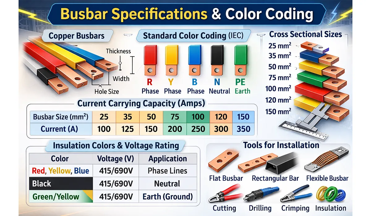
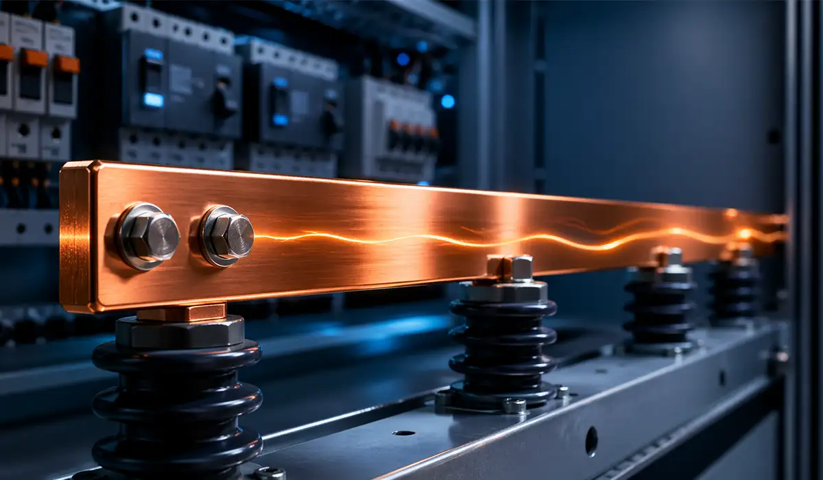
Phase busbars are identified with heat-resistant paint or sleeving. The phase busbars must carry the full rated current of the assembly with the applied rated diversity factor, and many project specifications require a margin above the main incoming device rating.
Neutral and earthing busbars run the full length of the board. As a working rule, both are sized at not less than half the phase busbar cross-section — but check two exceptions: a neutral carrying significant third-harmonic current from non-linear loads may need to equal or exceed the phase conductor, and the protective conductor should be verified against IEC 61439-1 rather than a flat percentage.
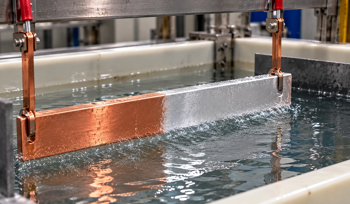
Connection points must be clean and, where possible, silver-plated before tightening. Busbars cut and punched to these specifications are typically produced on a dedicated busbar processing and fabrication system before installation.
Busbar Phase Arrangement by Routing Plane
Phase order follows a defined physical convention so that any electrician opening any board finds L1 in the expected position.
| Busbar routing plane | L1 | L2 | L3 |
|---|---|---|---|
| Horizontal run, horizontal plane | Front | Middle | Rear |
| Horizontal run, vertical plane | Top | Middle | Bottom |
| Vertical run, viewed from front | Left | Middle | Right |
| Vertical run, viewed from side | Front | Middle | Rear |
Table 7 — Phase busbar arrangement by routing plane. In every case L1 is nearest the front, top or left as viewed from the operating position.
A note on colours. Many regions still use the older red / yellow / blue convention for L1 / L2 / L3. Current IEC 60445 practice for cable cores is brown / black / grey. Busbar identification varies by national code, so confirm which convention applies before painting — mislabelled phases cause rotation errors on every motor fed from the board.
Busbar Sizing and Construction Requirements
| Item | Requirement |
|---|---|
| Phase busbars (L1, L2, L3) | Sized for rated current × rated diversity factor, verified for temperature rise |
| Neutral busbar (N) | ≥50% of phase cross-section as a minimum; full phase size where harmonic loading is significant; full board length |
| Earthing busbar (PE) | Verified against IEC 61439-1; full board length |
| Temperature rise limit | 70 K at terminals for external insulated conductors; 105 K ceiling for bare copper busbars |
| Clearance between live parts | Per IEC 61439-1 and IEC 60664-1 — millimeters, not centimeters. See the clearance guide. |
| Support insulators | Porcelain or synthetic resin, spacing set by short-circuit force calculation |
| Connection surface finish | Clean and abraded; silver or tin plating where specified |
Table 8 — Busbar sizing and construction requirements.
For the full method including ampacity tables and derating, see the guide to busbar sizing by current and temperature rise. A busbar bending machine is what makes these bars fit: accurate spacing, clean routing and repeatable bend radii are what let a board pass its verification rather than needing rework on site.
Sub-Distribution Board — Wall-Mounted Type
A wall-mounted board may be surface-mounted or flush-mounted and consists of three parts: the board box, the internal mounting frame, and the door frame with door.
- Board box up to 1 m height: 1.25 mm sheet, with punched or slotted conduit entries secured with brass bushes and nuts.
- Board box over 1 m height: 1.5 mm sheet.
- Internal frame: 1.5 mm steel sheet, removable with four screws.
- Door frame: at least 2 cm larger than the board box on all four sides for surface mounting.
Typical installation height is 210 cm from the top of the board to finished floor level — but check accessibility requirements in your jurisdiction, since many now cap the height of user-operable devices well below this.
Final Distribution Board — Circuit Protection Ratings
In final and lighting boards the main switch is commonly a rotary type protected by a cartridge fuse. Outgoing circuits are protected by MCBs or cartridge fuses.
| Circuit type | Rating |
|---|---|
| Alarm bell and call system | Maximum 4 A |
| Lighting circuits | Minimum 10 A |
| Socket outlets | Minimum 16 A |
Table 9 — Typical fuse and MCB ratings for outgoing circuits in final distribution boards. Actual ratings must follow the circuit design and cable size, not the table alone.
Internal wiring. All internal wiring uses single-core copper with insulation rated at least 1000 V. Maximum current density is 4 A/mm² of conductor cross-section. Only one conductor per terminal — connecting two or more to a single terminal is not permitted, because neither can then be relied on to carry its share.
Outdoor Power and Lighting Distribution Boards
Outdoor boards are floor-standing with galvanized steel frames and enclosures (minimum 2 mm sheet), or full-aluminium construction (minimum 3 mm sheet). The roof must be double-slope with edges turned inward, extending at least 5 cm beyond the board on all four sides. The door needs a sealing gasket and a special-key lock.
Boards are installed on a concrete or brick platform 20–25 cm above finished street level. In humid areas an angle-iron frame prevents direct board-to-concrete contact.
| Parameter | Requirement |
|---|---|
| Maximum height | 120 cm |
| Width | As required |
| Depth | 40 cm |
| Minimum IP rating | IP54; IP65 where directly exposed to weather or washdown |
| Platform height | 20–25 cm above grade |
| Platform wall thickness | 20–25 cm |
Table 10 — Dimensions and protection requirements for outdoor boards.
On IP ratings: the first digit covers solid particles and the second covers water. A rating written as IPX3 declares protection against spray water but no dust protection at all — the X means unrated, not exempt. For any outdoor enclosure, specify both digits. IP54 is the practical floor; IP65 where the board is exposed or hosed down.
Corrosion Protection and Surface Finishing
All enclosures and structural components are treated before painting. The process differs by climate and board category.
| Requirement | Dry climate (indoor) | Humid climate (indoor) | Outdoor / galvanized |
|---|---|---|---|
| Surface preparation | Derust, degrease, phosphate | Derust, degrease, phosphate | Derust, degrease, phosphate |
| Primer | 1 coat anti-rust primer | 1 coat anti-rust primer | Dedicated anti-rust plus 1 primer coat |
| Finish coats | Minimum 2 coats | Minimum 3 coats | Finish coat over primer |
| Humidity countermeasures | None required | Air circulation or internal anti-condensation heater | Sealed enclosure, IP54 minimum |
Table 11 — Corrosion protection and painting specification by climate and board category.
Devices and Instruments Inside the Board
| Category | Typical devices | Function |
|---|---|---|
| Measuring instruments | Voltmeter, ammeter, frequency meter, power factor meter, wattmeter, current transformer, hour meter | Monitor electrical parameters in real time |
| Protection and control | Cartridge and knife fuses, MCBs, MCCBs, motor-protection breakers, contactors with or without thermal overload, fused switch, rotary switch, selector switches, relays, timers | Protect against overload and short circuit; control switching |
| Alarm and signalling | Red signal lamp (ON / energized), green signal lamp (OFF / de-energized) | Visual indication of breaker and contactor status |
| Connection hardware | Phase, neutral and earth busbars, support insulators, cable lugs, terminal blocks | Distribute power from incoming supply to outgoing feeders |
Table 12 — Device categories inside a low-voltage distribution board.
Ammeter and Current Transformer Selection
Above roughly 60 A, direct-reading ammeters become impractical and a current transformer is used. The selection rule is to choose the next standard CT ratio at or above the maximum load, giving useful scale resolution without the pointer sitting at the top of its range in normal operation.
| Maximum load | CT ratio | Ammeter full scale | Notes |
|---|---|---|---|
| Up to 60 A | Direct — no CT | Direct reading | CT not normally required below 60 A |
| 61 – 80 A | 100 / 5 | 100 A | — |
| 81 – 160 A | 200 / 5 | 200 A | — |
| 161 – 320 A | 400 / 5 | 400 A | — |
| 321 – 400 A | 500 / 5 | 500 A | Example: 400 A load → 500/5 CT |
| 401 – 600 A | 750 / 5 | 750 A | — |
| 601 – 800 A | 1000 / 5 | 1000 A | — |
Table 13 — Current transformer ratios and ammeter full-scale values by load. Also check the CT burden against the connected instrument and lead resistance, and its accuracy class — Class 1 for indication, Class 0.5 or better for billing.
Motor Control Boards
The main switch in a motor control board is an automatic motor-protection breaker, typically with three ammeters and one voltmeter. The voltmeter selector switch is a seven-position type, giving all three phase-to-phase and all three phase-to-neutral readings plus off.
Sub-control circuits include a contactor and a protective relay, except where a separate starter panel is provided — in that case a fused switch or rotary switch with separate fuses is acceptable. Two signal lamps (red = ON, green = OFF) are provided per circuit.
Motor control centers are usually built as multi-compartment boards to Form 4b, because motor circuits are the ones most often worked on while the rest of the board stays live.
Choosing the Right Power Distribution Board
Selecting a distribution board is a sequence of four decisions, in this order.
First, establish which standard applies. Ordinary-person operation, ≤300 V to earth and ≤250 A means IEC 61439-3. Anything else is IEC 61439-2. This determines every verification requirement downstream.
Second, fix the separation form. Decide early whether circuits must be serviceable while the board is live. Form 4b costs more in money and depth, but retrofitting separation into a built board is not possible.
Third, size the busbars against real current with diversity applied, verified for temperature rise rather than a flat percentage margin, and confirm clearance and creepage against IEC 60664-1 — millimeters between live parts, metres of working space around the board.
Fourth, match the enclosure to the environment. IP54 minimum outdoors with both digits declared, corrosion treatment appropriate to the climate, and drainage under the board.
Get those four right and the rest is detail. For manufacturers producing the copper that goes inside these boards, PAYAPRESS builds the CNC busbar cutting, punching and bending machines that make bars fit first time.



Rate this article
Choose a rating from 1 to 5 stars.
No ratings yet