

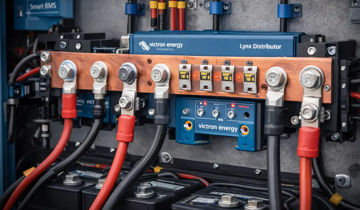





Where most guides stop at part numbers, this one walks through what a DC busbar system actually does in a real installation, how to pick between Victron busbar 150A, 250A, and 600A options, and how it all plays with the broader Victron Lynx Distributor and Lynx Smart BMS ecosystem. Getting the right busbar sizing and layout affects performance, longevity, and safety in your battery bank and inverter system.
Victron splits DC distribution into two families that are easy to confuse. Standalone busbars — 150 A, 250 A and 600 A, all rated 70 V DC — are bare copper bars with studs. The Lynx system is a modular range where fused, monitored and unfused modules bolt together on a shared 1000 A spine. Picking the wrong family is the most common and most expensive mistake in a Victron DC build, so this guide covers both, plus how to size for your actual continuous current rather than a nameplate figure.
If you want the wider context first, the guide to busbars in power distribution systems covers how the same principles scale from a 12 V camper to an industrial switchboard.
If you’d rather listen than read, feel free to play the audio file below for the rest of this article.
What Is a Busbar and Why Use One in DC Systems?
When you hear “busbar,” think of a metal strip inside your electrical panel that distributes power to various circuits. In electrical engineering, a busbar is a metallic conductor that handles high current, provides tap-off points, and lets connectors bolt directly onto it.
Why Busbars in DC Installations
In a DC distribution block for batteries and inverters, you want power flowing with as little resistance and thermal rise as possible. A busbar’s flat, broad copper shape provides excellent conductivity and cooling compared with bunches of cables. The surface area helps dissipate heat and keeps voltage drop low in high-current circuits.
Compared to conventional cable runs, busbars provide a neat, centralized battery bank connection point where everything ties together, allow easy branch connections without spaghetti-junction wiring, and improve reliability by reducing joins and crimps that create resistance and failure points.
Where Victron Busbars Fit in Modern Installations
Victron’s busbars are designed as part of low-voltage DC distribution in 12 V, 24 V, and 48 V systems where inverters, chargers, solar controllers (MPPTs), and battery banks all need solid power feeds. A busbar is typically used upstream of your inverter or battery charger and downstream of the battery, serving as the common node for positive and negative DC feeds.
In many setups you’ll see battery negative and positive feeds bonded into a centralized busbar, DC loads and inverter inputs tied to busbar posts, and shunts, fuses, and monitoring tied in at the busbar spine. Instead of running dozens of separate wires between devices, busbars shorten run lengths, cut voltage drop, and keep your DC power distribution tidy and safe. The stud-and-lug arrangement Victron uses is the same one described in the guide to terminal bus bar types, sizing and wiring, applied at DC voltages.
Victron Busbar Range: 150A, 250A and 600A Compared
Victron offers a range of standalone busbars rated for different current levels, all at 70 V DC. The choice comes down to expected load and future growth. Full specifications for each part number are on Victron’s busbars product page.
Victron Busbar 150A vs 250A vs 600A
Think of these like plumbing pipe sizes. A 150A unit may be plenty if you’re running a modest inverter and a handful of loads. But if you’re planning room for expansion — bigger inverters, more DC circuits — a 250A or 600A unit gives headroom, and you’ll thank yourself when you don’t need to rewire mid-project.
Table 1 — Victron Standalone Busbar Range
| Model | Rating | Connections | Best for |
|---|---|---|---|
| Busbar 150A | 150 A / 70 V | 4 or 6 high-current studs, or 2-pole with 10 or 20 screw terminals | Small systems: a modest inverter, a few DC loads |
| Busbar 250A | 250 A / 70 V | 4 or 6 high-current studs, or 2-pole with 6 or 12 screw terminals | Most small to medium installs |
| Busbar 600A | 600 A / 70 V | 4 or 8 high-current studs plus 8 low-current screw terminals | Larger battery banks, multiple inverters, mixed heavy and light circuits |
Every model ships with a removable protective cover, and the bars are tin-plated copper on stainless studs — the plating matters in marine and engine-bay installations where bare copper oxidises and joint resistance climbs.
The 600 A unit is the only one that mixes stud sizes, giving you heavy posts for main feeds alongside eight small screw terminals for monitoring taps and low-current circuits. On the others, every connection is the same size, so a bank of small circuits will consume studs you wanted for main feeds.
How to Size a Victron Busbar for Your Actual Load
Size on continuous current with margin, not on the inverter’s nameplate watts divided by nominal voltage. That shortcut undersizes almost every 12 V system.
Worked example — 3 kW inverter on 12 V. The naive calculation gives 3000 ÷ 12 = 250 A. Two things break it. Inverter efficiency at 12 V is typically 85–88%, and battery voltage under heavy load sags toward 12.0 V or lower, not the nominal 12.8 V. So:
3000 ÷ (12.0 × 0.87) ≈ 287 A continuous
That is already above a 250 A busbar’s rating before you add a single DC load or any surge. This system needs the 600 A busbar, not the 250 A. Running a busbar at or over its rating means higher joint temperatures, accelerated oxidation and eventual thermal runaway at a lug.
The same load at 48 V draws 3000 ÷ (48 × 0.93) ≈ 67 A, comfortably inside a 150 A bar. This is why system voltage drives busbar choice far more than inverter size does.
A workable rule: calculate continuous current at the lowest battery voltage you expect, add every DC load that can run at the same time, then add 25% headroom. If the result lands close to a rating boundary, go up a size. The price difference between a 250 A and a 600 A busbar is trivial next to rewiring a finished installation. The same logic applies to bars you fabricate yourself — see the method for sizing busbars by current and temperature rise.
Studs, Covers and Lug Sizing
Stud size varies by model and is not the same as the Lynx M8/M10 system described later. The 150 A busbar uses M6 studs; larger models use bigger hardware, and the 600 A unit mixes heavy studs with small screw terminals. Check the datasheet for your exact part number rather than assuming — a lug that doesn’t match its stud is the single most common cause of a hot joint.
Three rules that prevent most termination failures: use one lug per stud wherever possible, since stacked lugs never load evenly; keep the supplied covers fitted, because a dropped spanner across an unshrouded 600 A bar is a serious arc-flash event even at 12 V; and torque to the manufacturer’s figure with a calibrated wrench, not by feel.
Lynx Distributor vs Busbar: Which One Do You Need?
This is the decision most Victron builds get wrong, and the two products are not really substitutes.
A standalone busbar is a bare bar with studs. It distributes current and nothing else. Every circuit leaving it needs its own external fuse holder, mounted and wired separately. It is cheap, compact, and completely dumb — if a fuse blows, you find out by testing.
A Lynx Distributor is a modular busbar with four fuse positions built into the positive bar, each one monitored. When a MEGA fuse blows, a red LED lights on that position, the power LED turns red, and — if the module is connected to a Lynx Smart BMS — an alarm is pushed to the system. The negative bar carries four connections plus a dedicated ground.
Choose the standalone busbar when the system is small, the circuit count is fixed, you already have a fuse block, or budget is tight.
Choose the Lynx Distributor when you have four or more fused branches, you want fault visibility instead of a multimeter hunt, or you expect to expand. It is usually cheaper than buying a busbar plus four separate fuse holders once you count the mounting and wiring labour.
One caveat worth knowing: the fuse-status reporting only works with a Lynx Smart BMS. Pair a Distributor with a Lynx Shunt VE.Can instead and you keep the local LEDs but lose the system alarm.
The Victron Lynx System: All Five Modules Explained
The Lynx range is a modular DC backbone. Modules bolt together on a shared busbar spine, so you assemble the distribution you need rather than buying a fixed unit. The Lynx Power In, Lynx Class-T Power In, Lynx Distributor and Lynx Shunt VE.Can are all rated 1000 A nominal; the Smart BMS comes in 500 A and 1000 A.
Lynx Power In: The Unfused Busbar Module
The Lynx Power In is the simplest module in the range: a positive and a negative busbar with four connections each, rated 1000 A, available with M8 or M10 joints. It contains no fuses. Every battery, load or charger landing on it must be fused externally. The full specification is in Victron’s Lynx Power In manual.
That sounds like a limitation and usually isn’t. Its job is aggregating a battery bank — several batteries in parallel arriving at one clean node before the current moves on to a shunt or a Distributor. For two 1000 A bars in a housing that bolts straight into the rest of the Lynx system, it is the cheapest entry point into the range.
If you need fusing later, the Power In can be converted to hold fuses with the right hardware. You won’t get the monitoring board or the LEDs — for that you need the Distributor.
Lynx Class-T Power In
A variant that accepts two Class-T fuses and provides two battery connections, M10 only. Class-T fuses have the very high interrupting capacity that lithium banks demand, and this module exists largely because ABYC rules require that protection on lithium systems — Victron’s own lithium batteries do not include individual breakers or fuses. If you are building a marine lithium system to ABYC, this is usually the mandatory first module after the battery.
Lynx Distributor: Fused Branches with LED Monitoring
The Distributor holds four fuse-protected connections on the positive bar, each taking a standard MEGA fuse (not supplied), with individual fuse monitoring and a status LED per position. The negative bar carries four connections plus a ground — and in a vehicle or vessel that ground connection follows the same bonding logic as any ground bus bar in a fixed installation. Victron’s Lynx Distributor manual gives the wiring diagrams.
One detail that trips people up: the module interconnect joints are M8 or M10 depending on which version you bought, but the fuse and cable connections are always M8 on both. So an M10 Distributor does not mean M10 lugs.
Up to four Distributors can report fuse status to a single Lynx Smart BMS, and from there to a GX device and the VRM portal.
Lynx Shunt VE.Can: Monitoring Without Lithium Management
The Shunt VE.Can gives you battery monitoring on the Lynx spine — current, state of charge and history — reported over VE.Can to a GX device. It is the right choice when your batteries are not Victron lithium: lead-acid, AGM, gel, or third-party lithium with its own BMS.
The distinction matters because a Lynx distribution system normally contains either a Shunt VE.Can or a Smart BMS, never both. The Smart BMS only works with Victron Lithium Smart batteries; everything else uses the Shunt.
Lynx Smart BMS: Contactor, Shunt and Battery Management
The Lynx Smart BMS is more than a busbar module — it combines a main contactor, a current shunt and full lithium battery management on the Lynx platform. Batteries connect through it, and downstream modules like Distributors carry on the distribution. It monitors state of charge, reports over Bluetooth or to a GX device, and opens the contactor to disconnect the bank safely if cell voltage, temperature or current goes out of range.
It is available as a 500 A model with M8 or M10 busbars, or a 1000 A model with M10 busbars only — so the 500 A version is the one that can drop into an existing M8 system.
It only works with Victron Lithium Smart batteries. For any other chemistry, use the Lynx Shunt VE.Can instead.
Example Stack: Batteries → Smart BMS → Distributor → Loads
A typical robust build runs battery bank → Lynx Smart BMS (or a Power In plus Shunt VE.Can) → one or more Lynx Distributors → inverters, chargers and DC loads through MEGA fuses. Monitoring flows back through the shunt to a GX device and on to the VRM portal. The result keeps the batteries isolated, protected and serviceable without a tangle of individual cables.
M8 vs M10: What the Numbers Actually Mean
This is the most misunderstood spec in the Lynx range, and getting it wrong means ordering parts that physically will not join.
M8 and M10 refer to the interconnection joints between modules — the bolts that bridge one module’s busbar to the next. They do not describe your cable lugs.
The two are not compatible. An M8 Power In will not bolt to an M10 Distributor. Once you commit to a size, every module in that spine must match it.
Cable and fuse connections are always M8, on both versions, in every module. So your lug sizing is fixed regardless of which spine you choose.
Practically: M10 is the current direction of the range — several M8 products have been superseded by M10 equivalents. Build a new system in M10. Only choose M8 if you are extending an existing M8 spine.
Standards for Victron Busbar and Lynx Installations
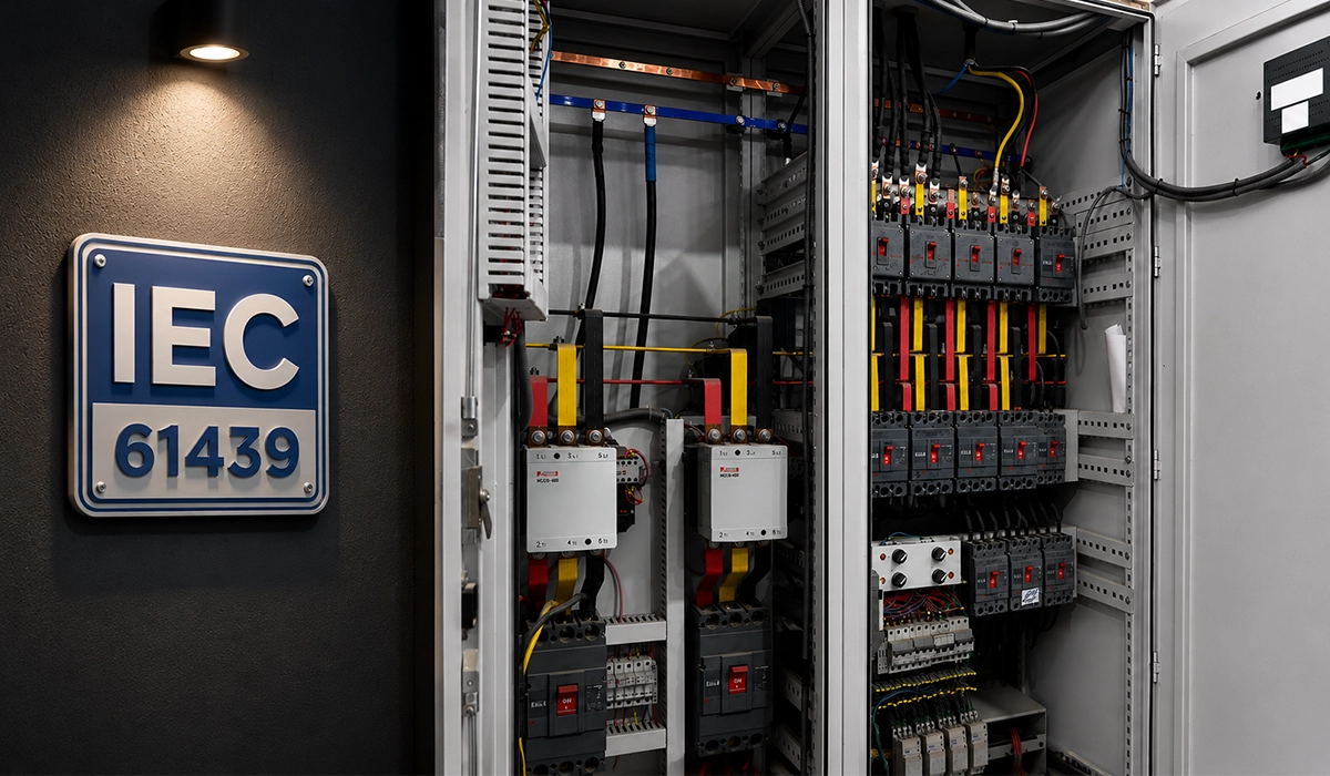
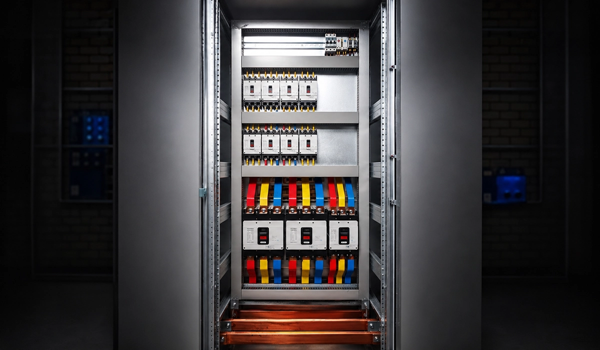
Assemblies containing these components must respect low-voltage assembly norms — IEC 61439 internationally, UL 508A in North America. IEC 61439 covers design verification for switchgear and controlgear assemblies up to 1000 V AC or 1500 V DC, including temperature rise, short-circuit withstand and mechanical integrity. UL 508A emphasises construction rules and component selection for industrial panels.
One clarification worth making, because it causes real confusion at inspection: the components carry product ratings, but compliance is a property of the finished assembly. A Lynx Distributor is not “IEC 61439 certified” on its own, and neither is any busbar. If your panel must carry a certification mark, the whole assembly gets verified — temperature rise, short-circuit withstand, clearance and creepage distances — not the parts individually. For mobile and marine installations, ABYC and ISO 13297 are usually more relevant than either IEC 61439 or UL 508A.
If the DC system feeds a fixed installation rather than a vehicle, the broader rules for electrical power distribution boards apply downstream of the inverter.
Calculating Current and Temperature Rise Considerations
When sizing your busbar and wiring plan, consider continuous vs intermittent loads, ambient temperature, and enclosure ventilation. A busbar running near its rated limit in a cramped, hot enclosure will see more temperature rise than the same part in a ventilated cabinet. Derating for temperature and knowing how much continuous current your layout will carry helps you pick the right busbar class and mounting position. Follow manufacturer torque specs on terminals to keep resistance low and heating in check.
Fuse Selection and Coordination for Victron DC Systems
Two practical notes. The Distributor’s slots take MEGA fuses, which are not included — budget for them separately and buy the ratings before commissioning day. And for lithium banks, check whether your installation requires Class-T protection at the battery: MEGA fuses do not have the interrupting capacity that a large lithium bank can deliver into a dead short, which is exactly why the Lynx Class-T Power In exists.
Installation: Wiring, Torque, and Layout Tips
Practical wiring tips make your installation safer and easier to maintain. Mount busbars close to batteries and inverters to minimise voltage drop. Use cables with the correct lug size and rated insulation, and label everything clearly — DC busbar layout clarity saves troubleshooting time. Respect torque specs on the M8 cable and fuse connections to avoid loose joints. Common mistakes include stacking too many lugs on one post, mixing lug and stud sizes without adapters, and ignoring protective covers, all of which compromise safety and performance.
Common Mistakes to Avoid
Even seasoned installers sometimes slip up. Typical pitfalls include mixing M8 and M10 Lynx modules in one spine, which will not physically join; stacking too many cables under one lug leading to uneven torque; skipping protective covers, which invites accidental shorts; and undersizing fuses or placing them incorrectly relative to the busbar feed. Avoiding these saves time and prevents shock hazards or system downtime.
Conclusion
Sizing, wiring, and integrating a Victron busbar into your power system is more than a parts list. It’s about creating a DC distribution backbone that’s safe, scalable, and compatible with the rest of your system — whether that’s a simple inverter in an RV, a home solar setup, or an industrial energy storage system. Choosing between Victron busbar 150A, 250A, and 600A isn’t guesswork: it’s about matching your expected currents at the lowest battery voltage you expect, leaving room for growth, and respecting practical layout principles that reduce voltage drop and heat.
By incorporating modular components like the Lynx Power In, Lynx Distributor and Lynx Smart BMS, you build in visibility and protection that go beyond bare copper bars. Just remember that compliance belongs to the finished assembly, not the individual parts, and that ABYC or ISO 13297 will usually govern a marine or mobile build before IEC 61439 does.
For panel builders fabricating their own bars rather than buying them off the shelf, PAYAPRESS makes the CNC busbar cutting, punching and bending machines that produce flat, clean, repeatable copper.


Rate this article
Choose a rating from 1 to 5 stars.
No ratings yet