







If you’d rather listen than read, feel free to play the audio file below for the rest of this article.
Busbar Joint Cover at a Glance
A busbar joint cover is a small part with a big job. It closes the gap that sleeving leaves at the bolted joint, and it only works when it goes on in the right order. This guide covers the parts, the installation sequence, how to cut the cover to the conductor, and the mistakes that cause rework at commissioning. This kind of insulation detail sits within the broader design principles covered in our guide to busbars for power distribution.
Why a Busbar Joint Needs Its Own Cover
A busbar joint cover closes the one gap busbar insulation leaves open, because the bolted faces underneath it are prepared bare and stay that way.
Sleeving runs the length of the conductor and stops at the joint. The mating faces are cleaned and greased before bolting, so no sleeve sits between them, leaving bare metal exactly where two bars meet.
Getting this insulation detail right is part of the larger job of fitting busbars correctly inside the panel. Our guide to busbars in electrical panels covers that broader context.
ABB fills it with hardware. Its ZS3.2 manual treats bolt connections in the busbar system as normally covered by insulating covers. Its ZS1 manual gives the design aim: sleeves on the conductors plus covers on the joints leave an arrangement free of arc fault points of origin.
Panel builders often call the part busbar insulation boots. Later ZS1 documentation marks the cover steps as applying to insulated busbars.
If you would like to explore this subject further, you can read more about it here.
The Parts: Cover, Lid and Holder
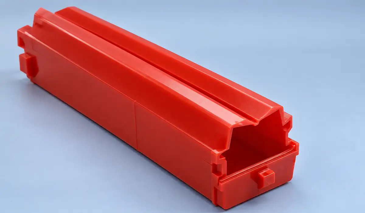
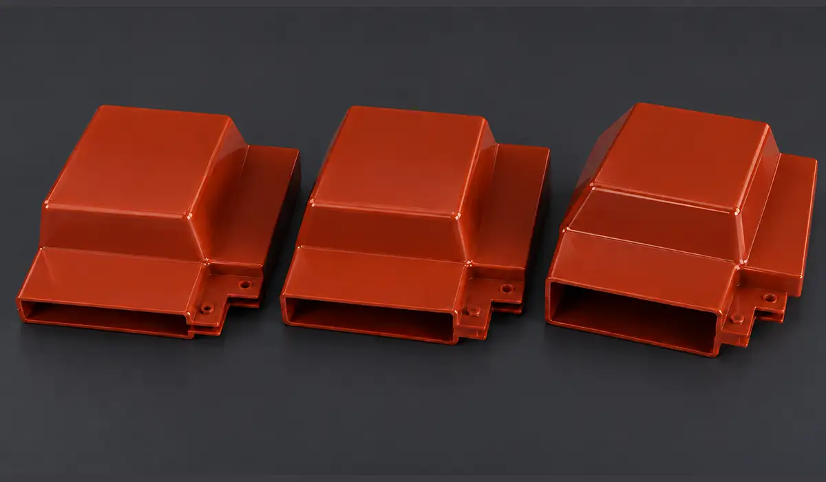
Three parts make one busbar insulation cover work: the shell over the joint, the lid that closes it, and the holder that carries the weight.
| Part | What it does | When it goes on |
|---|---|---|
| Insulating cover | Shell over the joint | Threaded on before bolting |
| Lid | Slides on and clicks home | After the joint is bolted |
| Cover holder | Supports the cover from each bar end | After bolting, at lower torque |
The set varies with the design. In ZS1 end panels ABB fits supports with washers to hold the covers, and fits the lid at the 17.5 kV rating. Check the parts list for your panel rather than assuming every joint takes the same three pieces.
You can also save a copy for later, which is helpful if you plan to return to this more than once.
These three parts are just one detail inside the much wider set of decisions that make up a busbar arrangement. Our guide to busbar arrangements covers that bigger picture.
Installation Order, Step by Step
ABB’s order puts the busbar joint cover on the bar before the first bolt, and every later step depends on that one.
- Prepare the covers and lids to suit the busbar connections on this panel.
- Thread them onto the busbar before you make the joint.
- Clean and grease the contact faces of the connection.
- Install the busbars panel by panel, bolting the elements in line with the flat tee-off conductor. Torque the joint bolts to the table and fit two dished washers per bolt.
- Bolt one holder to each busbar end to carry the cover, tightening those screws to a lower torque than the joint bolts.
- Position the cover and lid over the bolted joint, then slide the lid on until it clicks.
Two of those are easy to reverse by habit. The holder goes on after the joint is bolted, not before, and the lid goes on last of all.
Step 2 is the one that bites. A cover left in the box while the bolts go in cannot be threaded on afterwards. The joint has to come apart, the faces need preparing again, and a five-minute step becomes an hour.
Getting the joint bolted correctly before the cover goes on is really just one part of building a sound termination in the first place. Our guide to terminal bus bars covers that connection point.
Cutting the Cover to the Conductor
ABB expects you to cut the cover and lid during assembly so the opening matches the cross-section of the feeder or busbar passing through it.
The drawings do the deciding. ABB marks defined cutting locations for different conductor systems, including tee-off systems of 2x100x10 and 2x120x10 and the D 100 busbar system. Cut at the location marked for the conductor in front of you and nowhere else.
An oversized opening defeats the part. The cover stops being a closed shell and becomes a shield with a gap at the point where the conductor enters.
Cutting to the right mark matters just as much back at the fabrication stage, where bending technique decides the conductor’s final shape. Our guide to copper busbar bending covers that process.
Checks Before You Close and Energize
A short walk-through before the lid goes on saves a lot of rework later. Run through these points joint by joint:
- Every joint bolt is torqued to the table and carries the correct washers.
- The holders are fitted at each bar end and tightened to their own, lower torque.
- The cover sits square over the joint and the cut-out matches the conductor passing through it.
- The lid is fully home, with the click confirming it is closed.
- No covers or lids are left over in the box, which usually means one joint was missed.
Following the same checklist on every panel makes missing parts and skipped steps obvious before commissioning, not during it.
A joint that passes this checklist still has to survive a real fault event, which is a separate mechanical question. Our guide to busbar short-circuit withstand covers that requirement.
Mistakes That Show Up at Commissioning
Four mistakes account for most busbar joint cover rework, and ABB’s own step order predicts every one.
- Cover not threaded on first. The joint comes apart, and the crew prepares the faces a second time.
- Holder screws over-tightened. ABB calls for a lower torque here, so the joint table does not apply.
- Lid not clicked home. Without the click you have no confirmation that the cover is closed.
- Cut-out made at the wrong mark. The opening no longer matches the conductor, so the cover is scrap.
Many of these commissioning issues trace back to how the contact surfaces themselves were finished before assembly. Our guide to silver-plated busbar covers that surface treatment.
Conclusion about Busbar Joint Covers
A busbar joint cover only sits properly on a joint made to drawing, with holes and lengths where the design put them. Get that right in the shop, and the cover becomes the easiest part of the whole assembly.
The pattern across every step in this guide is the same: the cover is simple, but the order is not forgiving. The cover goes onto the bar before the first bolt. The holder goes on after the joint is bolted, at its own lower torque. The lid goes on last and is confirmed by its click. Each of these steps depends on the one before it, and a skipped or reversed step cannot be fixed quietly at the end.
Cutting the cover to the conductor deserves the same discipline. Use the cutting location marked for the conductor system in front of you, because an opening that is too large turns a closed shell into a shield with a gap. Most of the rework described above is not caused by faulty parts. It comes from small habits, such as leaving covers in the box, applying the wrong torque or trimming at the wrong mark.
The best protection is a routine. Lay out the covers, lids and holders for each joint before the first bar goes into place, work from the manufacturer’s drawings and parts list rather than from memory, and treat a leftover cover or lid in the box as a sign that a joint was missed. Doing this work properly in the shop is far cheaper than finding the problem at commissioning, when joints have to be opened, faces prepared again and covers replaced.
A clean, correctly ordered installation also gives the next person who opens the panel a joint they can read and trust. Always follow the manufacturer’s manual for your specific panel type and rating, since the parts and details can vary between designs.
Getting the cover right is one part of specifying the whole busbar system correctly for an LV panel. Our guide to busbars for LV panels covers the rest of that decision.
FAQ about Busbar Joint Covers



Rate this article
Choose a rating from 1 to 5 stars.
No ratings yet