








For your convenience, if you prefer listening, you can listen to the rest of this article via the audio file below.
Why Copper Busbar Current Rating Matters?
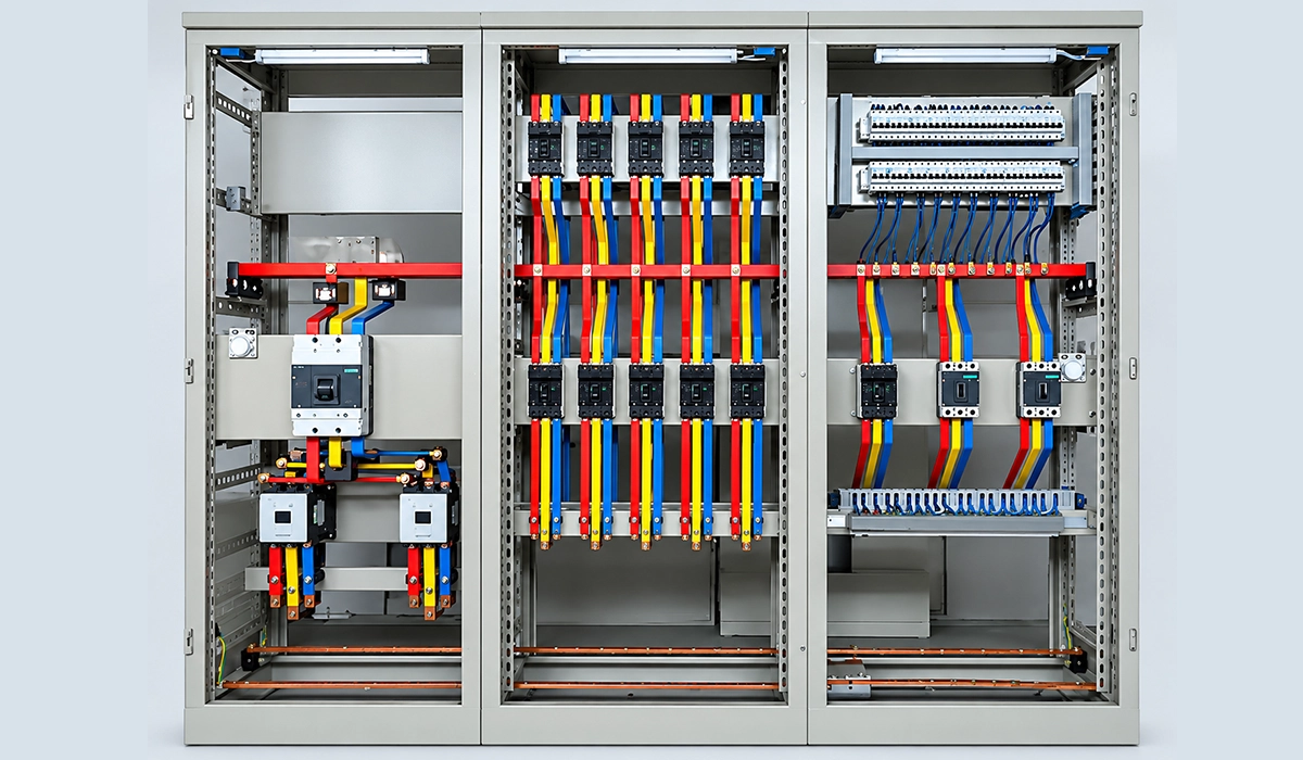
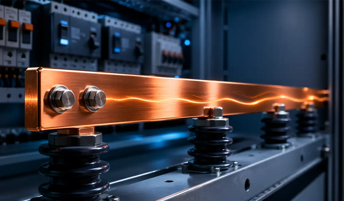
A copper busbar is a rigid conductor, usually a flat copper busbar, that distributes current inside switchgear, panel boards, MCCs, and distribution boards. Copper suits this job because it offers high electrical conductivity, strong mechanical behavior, and reliable joint performance. In high-conductivity copper, the IACS reference value gives about 58 MS/m at 20°C, so designers can keep compact profiles without excessive resistance. For a broader context, see this guide on electrical busbars for power distribution.
However, copper busbar current rating is not a fixed property of copper alone. It depends on width × thickness, ambient temperature, permissible temperature rise, cooling, enclosure design, and joint quality. For example, the same rectangular copper bar can carry more current in open air than inside a crowded switchboard.
As a rule of thumb, current density copper busbar practice often falls between 1.0 and 3.0 A/mm². Conservative enclosed assemblies use the lower range, while open busbars with better airflow can use the higher range. Therefore, a copper busbar selection guide must combine thermal, mechanical, and fault-current checks.
Copper Busbar Current Rating Table by Cross-Section
The table below works as a practical busbar ampacity table for early design and comparison. It also functions as a copper busbar size chart because it links physical size, cross-section, mass, resistance, and current capacity in one place. Use it for concept design, then verify the final assembly against the applicable standard and manufacturer data. For related panel types, see types of power distribution boards.
The values cover common rectangular sizes from 15×3 mm to 120×10 mm. They support rectangular busbar sizing for LV panels, bus ducts, distribution boards, and switchgear assemblies. In addition, the table helps answer real design questions such as what size copper busbar for 1000 amps or how thick should a copper busbar be for 400A.
For example, 25×5 mm gives about 415 A at ΔT=35°C, while 40×10 mm reaches about 1020 A. That makes the copper flat bar electrical rating table useful for fast screening before detailed thermal verification.
| Width (mm) | Thickness (mm) | Cross-Section (mm²) | Weight (kg/m) | DC Resistance (μΩ/m at 20°C) | Current Rating at ΔT = 35°C (A) | Current Rating at ΔT = 50°C (A) |
|---|---|---|---|---|---|---|
| 15 | 3 | 45 | 0.40 | 383 | 190 | 230 |
| 20 | 3 | 60 | 0.54 | 287 | 240 | 290 |
| 25 | 3 | 75 | 0.67 | 230 | 285 | 345 |
| 25 | 5 | 125 | 1.11 | 138 | 415 | 500 |
| 30 | 5 | 150 | 1.34 | 115 | 480 | 580 |
| 40 | 5 | 200 | 1.78 | 86 | 595 | 720 |
| 40 | 10 | 400 | 3.57 | 43 | 1020 | 1240 |
| 50 | 5 | 250 | 2.23 | 69 | 710 | 860 |
| 50 | 10 | 500 | 4.46 | 34.4 | 1220 | 1480 |
| 60 | 5 | 300 | 2.67 | 57.5 | 825 | 1000 |
| 60 | 10 | 600 | 5.35 | 28.7 | 1390 | 1690 |
| 80 | 5 | 400 | 3.57 | 43 | 1020 | 1240 |
| 80 | 10 | 800 | 7.13 | 21.5 | 1740 | 2120 |
| 100 | 10 | 1000 | 8.90 | 17.2 | 2110 | 2560 |
| 120 | 10 | 1200 | 10.7 | 14.4 | 2450 | 2980 |
Design note: Ratings assume a single flat bar mounted in still air at 40°C ambient. ΔT=35°C gives a conductor temperature of 75°C; ΔT=50°C gives 90°C. Derate for higher ambient temperature, enclosed installation, poor ventilation, or multiple stacked bars.
Download this resource to compare the details more easily during your review process.
How to Read and Use the Busbar Rating Table
Read the two ΔT columns as thermal limits, not as universal pass/fail values. ΔT=35°C gives a conservative rating when the ambient temperature is 40°C. ΔT=50°C allows more current, but it also raises conductor temperature and increases stress on insulation, joints, and nearby components. For compact DC systems, see Victron busbar applications.
Next, check the baseline condition. This current carrying capacity table assumes 40°C ambient and still-air cooling. If the panel runs at 50°C, the same bar cannot reject heat as easily. Therefore, you must apply the copper busbar derating factor temperature before approving the size.
Installation also matters. Open bars release heat from both faces and edges, while enclosed bars may sit near breakers, cable ducts, barriers, and hot devices. As a result, busbar heat dissipation can drop sharply inside compact switchgear.
Finally, avoid assuming that parallel bars multiply rating perfectly. Stacked conductors reduce surface cooling on inner faces. For reliable busbar conductor sizing, combine the table, derating factors, current density, and short-circuit withstand.
Derating Factors — When to Adjust the Rated Current
Derating adjusts the table value when real conditions differ from the rating baseline. This matters because busbar temperature rise depends on heat generation and heat removal. Joule heating rises with current squared, while cooling depends on air movement, surface area, and enclosure layout. For context on reactive power and efficiency, see power factor.
Use derating when ambient temperature exceeds 40°C, when bars sit inside tight enclosures, when several bars run side by side, or when stacked bars reduce exposed surface. Also apply judgment when harmonics, poor ventilation, or high duty cycles increase losses.
A simple screening formula is:
Adjusted current = Table current × ambient factor × stacking factor × installation factor
However, do not treat this as final IEC verification. It supports early engineering decisions. The final design still needs assembly-level checks for temperature rise, clearances, creepage, insulation rating, and fault withstand.
In practice, conservative derating reduces warranty risk and field failures. In contrast, aggressive sizing may pass a spreadsheet but fail during hot weather, continuous loading, or poor maintenance.
For engineers and procurement teams, this downloadable file provides a useful reference for decision-making.
Ambient Temperature Derating
The table below gives practical screening factors relative to a 40°C baseline. Use lower current when the room or enclosure runs hotter. In cooler rooms, you may gain margin, but only if all components and local standards allow it.
| Ambient Temperature (°C) | Derating Factor |
|---|---|
| 25 | 1.10 |
| 30 | 1.07 |
| 35 | 1.03 |
| 40 | 1.00 |
| 45 | 0.97 |
| 50 | 0.93 |
| 55 | 0.89 |
| 60 | 0.85 |
Multiple Bars in Parallel — Stacking Derating
Parallel bars increase capacity, but not linearly. Inner surfaces lose cooling, so each added bar contributes less than a fully exposed single bar. Use these factors for early stacked-bar screening.
| Number of Bars in Parallel | Current Capacity Factor per Bar |
|---|---|
| 1 | 1.00 |
| 2 | 0.90 |
| 3 | 0.80 |
| 4 | 0.75 |
Example: one 80×10 mm bar carries 1740 A at ΔT=35°C. Two stacked bars carry:
2 × 1740 × 0.90 = 3132 A
Current Density Guide for Copper Busbars
Current density gives a fast check before detailed rating verification. It divides load current by conductor area and expresses the result as busbar ampere per mm². This method helps engineers compare alternatives, but it cannot replace a full busbar ampacity calculation formula explained with thermal limits. For terminal connection practices, see terminal busbar.
For enclosed switchgear, many designers use 1.2–1.8 A/mm² as a conservative range. Open busbars with better ventilation may use 1.8–2.5 A/mm². Outdoor open-air systems can go higher, while intermittent loads may allow short-duration peaks.
| Application Type | Recommended Current Density (A/mm²) |
|---|---|
| Enclosed Switchgear Panels | 1.2–1.8 |
| Open Busbars, Well-Ventilated | 1.8–2.5 |
| Outdoor Open-Air Installations | 2.0–3.0 |
| Short-Duration or Intermittent Loads | Up to 3.5 |
Excessive current density creates more than insulation risk. It raises joint temperature, accelerates oxidation, increases voltage drop, and reduces long-term reliability. Therefore, use current density as a warning signal, then confirm the busbar cross section current capacity from tables and tests.
This external page provides additional insights that may help with your evaluation.
Short Circuit Withstand Capacity of Copper Busbars
For a simple adiabatic thermal check, engineers often use:
I²t = k² × S²
Where I is fault current in amperes, t is duration in seconds, S is cross-section in mm², and k is the copper material constant. For copper starting near 20°C and ending near 200°C, k is often approximated as 141 A√s/mm².
Example: a 500 mm² copper busbar gives:
I = 141 × 500 / √1 = 70,500 A for 1 second
This check does not cover mechanical forces, support spacing, or bracing. Therefore, verify thermal and dynamic withstand before releasing large electrical busbar design projects.
A busbar must carry load current continuously and also survive fault current for a defined time. Therefore, busbar short circuit withstand is separate from ampacity. IEC 60865-1 covers the calculation of mechanical and thermal effects on rigid and flexible conductors. For flexible conductor alternatives, see flexible busbar types and sizing.
Copper vs Aluminum Busbars — Current Rating Comparison
| Property | Copper Busbar | Aluminum Busbar |
|---|---|---|
| Conductivity (MS/m) | ~58 | ~35 |
| Current Capacity, Same Size | Higher, About 1.6× | Lower |
| Weight, Same Size | Heavier | About 3× Lighter |
| Cost | Higher | Lower |
| Corrosion Resistance | Good | Requires Joint Treatment |
| Typical Current Density | 1.5–3.0 A/mm² | 1.0–2.0 A/mm² |
| Jointing Method | Bolted or Welded | Bolted with Suitable Hardware |
Choose copper when compact size, lower resistance, tight panel geometry, and high joint reliability matter. Choose aluminum when weight and cost dominate, especially in larger installations with enough physical space.
Also compare busbars with cables carefully. A copper busbar vs cable current rating comparison must include cooling, bending space, termination heat, short-circuit forces, and maintenance access.
A copper vs aluminum busbar decision is an engineering trade-off. Copper gives higher conductivity and compactness. Aluminum reduces weight and often lowers material cost. However, aluminum needs more area for the same current and requires careful joint preparation. For grounding conductor selection, see ground bus bar.
How to Select the Right Copper Busbar — Step-by-Step
- Determine the maximum continuous current.
- Define ambient temperature and installation method.
- Apply derating for temperature, enclosure, and stacking.
- Calculate required area using target current density.
- Select the nearest standard size from the table.
- Verify short-circuit withstand against system fault level.
- Check mechanical deflection, supports, clearances, and joint access.
Worked example: assume 630 A in a 45°C enclosed panel with two stacked bars. Ambient factor = 0.97. Stacking factor = 0.90 per bar. A 25×5 mm pair gives 2 × 415 × 0.90 × 0.97 = 725 A, so it passes the table check.
However, current density is 630 / 250 = 2.52 A/mm², which is high for enclosed panels. Therefore, a more conservative selection is two 40×5 mm bars. They provide 400 mm² total area, reduce density to 1.58 A/mm², and improve thermal margin.
This final check prevents a common mistake: selecting only by table ampacity while ignoring current density, enclosure heat, and future load growth.
A reliable copper busbar current rating starts with load and environment, not only with size. Use this process when asking how to select copper busbar size for switchgear or preparing a busbar sizing calculation for panel board. For software-assisted design, see busbar design software.
Conclusion about Copper Busbar Current Ratings
For quick sizing, use the table to identify a candidate bar. Next, apply derating factors and confirm that the current density remains practical for the enclosure. Finally, verify fault withstand, support spacing, joint design, and the applicable local standard.
For deeper design work, consult CDA Publication 22, IEC 61439, IEC 60865-1, and the equipment manufacturer’s tested data. In PAYAPRESS content, natural internal anchors could include busbar bending machine, busbar punching machine, and busbar machine for switchgear panels.
The correct copper busbar current rating comes from a design sequence, not from one isolated table. Start with continuous load current. Then check ambient temperature, installation method, derating, current density, and short-circuit withstand. For a complete overview of busbar arrangements, see busbar arrangements guide.


Rate this article
Choose a rating from 1 to 5 stars.
No ratings yet