



If you’d rather listen than read, feel free to play the audio file below for the rest of this article.
The Power Chain: Grid Connection to Charging Point
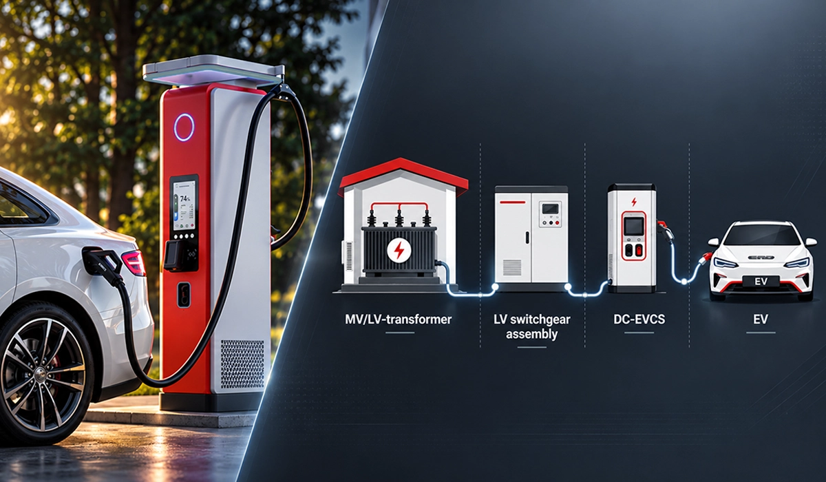
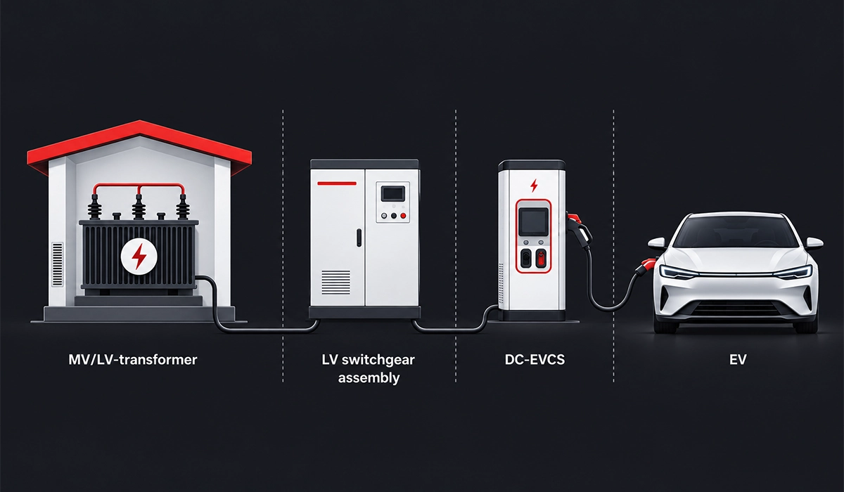
So, how is power distributed in an EV charging station? Large sites usually take power from the medium-voltage grid through an MV/LV transformer, then feed an LV switchboard. From there, a feeder runs to each charger or group of chargers. In this EV charging power distribution chain, the transformer and main busbars carry the full site demand, while each feeder carries its share.
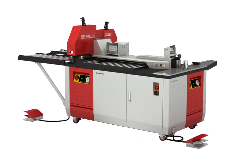
The sheet metal corner forming machine produces seamless, weld-free corners in sheet metal enclosures with thicknesses from 0.5 to 2 mm. Its cold-forming technology reduces the need for welding, grinding, and polishing while maintaining consistent corner geometry.
AC vs DC Fast Charging: What Changes
AC charging sends grid-frequency power to the car, and the vehicle’s onboard charger converts it to DC. These units usually deliver up to about 22 kW (typical), so one standard feeder can serve several of them. DC fast charging power distribution works differently. The charger cabinet holds the AC/DC rectifier and the DC/DC converter, and it delivers DC straight to the battery at 50–350 kW or more (typical range). As a result, a 150–350 kW unit draws roughly 220–500 A at 400 V (hypothetical estimate). In addition, many sites split the hardware into a power cabinet and several dispensers, so power can shift between parking bays. That split moves the heaviest conductors into the power cabinet.
Every stage of this chain relies on the same busbar principles used across modern facilities. For the fundamentals of busbar types, design and applications, see our guide to electrical busbar systems.
Where Busbars Sit in the Chain
So, do EV chargers use busbars? Yes, at almost every stage, although each EV charging busbar does a different job. The simple chain below marks the main busbar locations in bold:
MV/LV transformer → LV switchboard busbars → feeders (cable or busbar trunking) → charger cabinet input and DC busbars → charging point
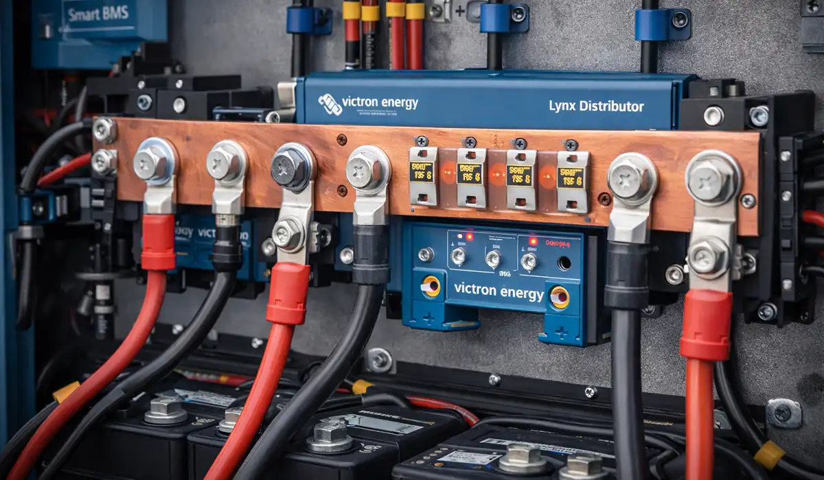
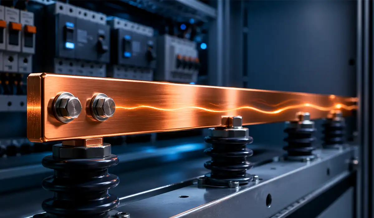
First, the main busbars of the EV charger switchboard collect the transformer current and share it between the outgoing feeders. Next, a site can replace individual feeder cables with busbar trunking, which runs along the parking bays and feeds each charger through a tap-off unit. Finally, inside each DC charger, rigid and laminated bars link the input terminals, the rectifier, the DC link capacitors and the output stage. Busbars therefore appear wherever current is high and space is short. Cables, in contrast, still make sense for the final flexible link to the vehicle and for small, low-current circuits such as control and auxiliary supplies.
Distribution Architectures Compared
Most sites choose between three layouts, and the choice shapes EV charging station design for years. The real question, busbar trunking vs cable for EV chargers, depends on site size, growth plans and how often the layout will change.
Research labs now test hubs that share one DC bus, so the third option is moving from theory into practice. NREL and its partners compare AC-coupled and DC-coupled hub designs and set out design guidelines in their DC hub report.
Whichever layout you choose, it starts at a distribution board that splits the incoming supply. Compare the main options in our guide to distribution board types.
Radial Cable Distribution
In a radial layout, each charger gets its own cable from the LV switchboard. Every electrician knows this approach, and the parts are easy to source. However, a large hub needs many heavy cables, each with its own trench, glands and terminations. Adding a charger later often means new trenching, or a spare way that someone planned years earlier. Radial cable distribution therefore suits small sites, or sites with a fixed layout that will rarely change. It also keeps faults local, since each charger has its own protective device.
Busbar Trunking Systems
Busbar trunking for EV charging replaces many cables with one enclosed busbar run along the bays. Tap-off units then feed each charger, so adding a unit means fitting a new tap-off rather than pulling a new cable. Several manufacturers now offer EV-focused systems. For example, Schneider Electric describes its Canalis for EV range as plug-and-play, reusable and installable in less than four days (manufacturer claim). Other suppliers, such as Molex and Rogers, focus on rigid, flexible or laminated busbars inside the charger itself (manufacturer information). However, outdoor trunking needs solid mechanical protection, and its first design takes more planning than a cable schedule. In return, the site gains fewer terminations and a tidier layout along each row of bays.
Shared DC Bus for Charging Hubs
A DC bus architecture for fast charging hubs moves the AC/DC conversion into one central converter. That converter feeds a common DC bus, and DC/DC units then supply each dispenser. Batteries and solar panels can join the same bus with fewer conversion stages, so charging hub electrical design gains efficiency and flexibility. With storage on the bus, the grid connection can also be sized closer to average demand than to the peak. However, DC faults are harder to interrupt, the central converter becomes a single point of failure, and the standards are still maturing.
The table compares the three layouts in qualitative terms.
| Factor | Radial cable | Busbar trunking | Shared DC bus |
|---|---|---|---|
| Install time | Slow on large sites | Fast; prefabricated | Slow; custom design |
| Flexibility | Low | High; tap-offs move | High for storage and PV |
| Expansion | New cable per charger | Add tap-off units | Add DC/DC modules |
| Maintenance | Many terminations | Fewer joints to check | Specialist power electronics |
| Cost trend | Low on small sites | Lower as sites grow | Highest today; few products |
Load Management and Sizing
Sizing decides whether a site meets demand or trips its main breaker on a busy afternoon. Good EV charging load management lets designers size for real demand rather than the sum of every nameplate.
Feeder sizing starts from the installation rules for the circuits that supply each charging point. The IEC catalogue entry sets out the scope of circuits that supply energy to electric vehicles in its IEC 60364-7-722 summary.
Once demand is known, the next step is choosing a busbar cross-section that carries it safely. Our busbar sizing guide walks through that calculation step by step.
Diversity and Load Management
Not every charger runs at full power at once. Vehicles arrive at different times, some bays sit empty, and batteries draw less power as they fill. The diversity factor captures this effect: it is the real peak demand divided by the sum of all charger ratings.
For example, ten 150 kW chargers add up to 1.5 MW. Yet the measured peak might stay near 900 kW, a diversity factor of 0.6 (hypothetical estimate). However, designers should not simply assume that figure. Many codes allow the lower value only when an automatic load management system enforces the limit. That system reads the site meter and trims charging power, through protocols such as OCPP, before the supply limit is reached. As a result, a site can host more chargers on the same connection, while drivers see only a modest drop in peak speed. Static limits suit simple sites, whereas dynamic limits follow other building loads in real time.
Sizing Feeders and Busbars
So, how do you size electrical supply for a charging hub? First, set the maximum site demand, either from the load management limit or from the full charger ratings. Treat charging as a continuous load, because sessions can last for hours. Next, convert demand to current. For example, a 900 kW cap at 400 V three-phase gives about 1,300 A (hypothetical estimate), so the main busbar might take a 1,600 A rating.
Then apply derating for ambient temperature, grouping and installation method, since outdoor cabinets and buried cables run warm. In addition, check voltage drop on long runs and allow for harmonics from the rectifiers. Finally, add spare capacity and spare ways, because hubs rarely stay at their first size. That is how to size feeders for EV charging: real demand first, then thermal limits, then growth. The same logic sizes the MV/LV transformer, which the utility usually confirms.
Inside the Charger: DC Link and Laminated Busbars
So, what is a DC link in a charger? It is the intermediate DC stage between the input rectifier and the output DC/DC converter. A bank of capacitors holds this voltage steady, while power electronics, usually IGBT or silicon carbide modules, switch it at high frequency to control the output. On a 400 V supply, this link usually sits at roughly 700–800 V DC (typical), so every connection carries both high voltage and fast-changing current.
Fast switching, however, creates a problem. Every conductor loop has stray inductance, and when current changes quickly, that inductance produces voltage spikes across the switches. Larger spikes force designers to slow the switching, add snubbers or choose higher-voltage parts, and each option costs efficiency or money. Therefore, a low inductance busbar for DC link connections is one of the simplest ways to protect the semiconductors and raise efficiency. It also reduces electromagnetic noise, which helps the charger pass its emissions tests.
A laminated busbar stacks thin copper layers for the positive and negative paths, with insulating film between them. Because the two currents flow close together in opposite directions, their magnetic fields largely cancel, and stray inductance falls. That is why laminated busbar EV charging designs are common in high-power DC cabinets (typical). In addition, the flat stack is compact, it repeats exactly from unit to unit, and it cuts wiring errors during assembly.
Thermal management matters as well. Laminated bars spread heat over a wide surface, and designers can mount them close to cooled modules or heatsinks. However, the insulation film sets its own temperature limit, so the bar, the capacitors and the switches must share one thermal budget. Liquid-cooled chargers ease that budget, but they also add pumps, hoses and leak checks to the design.
Higher charging voltages raise the stakes for every DC link connection, which is why component suppliers publish specific design guidance. Rogers, for example, states that charging-station busbars need low inductance and low loss for efficient, cool operation in its overview of charging station busbars.
Laminated designs are one sign of how quickly busbar technology is changing. Explore the future busbar trends shaping power electronics and distribution.
Fabricating Busbars for Switchboards and Charger Cabinets
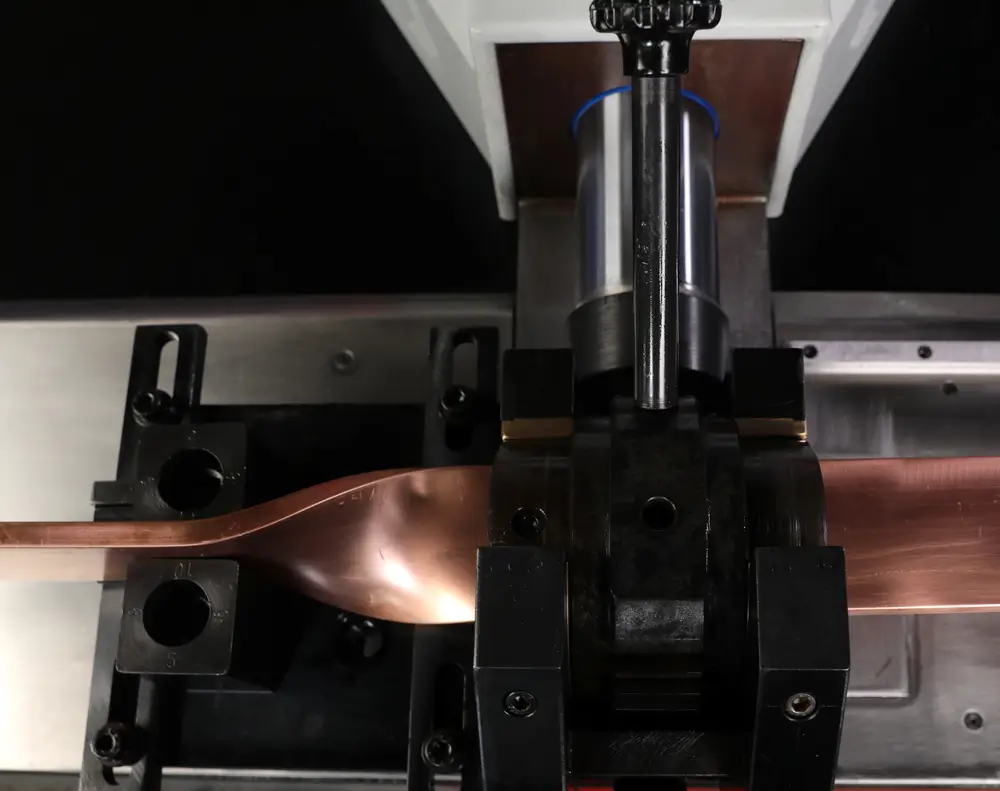
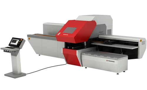
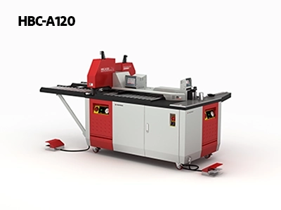
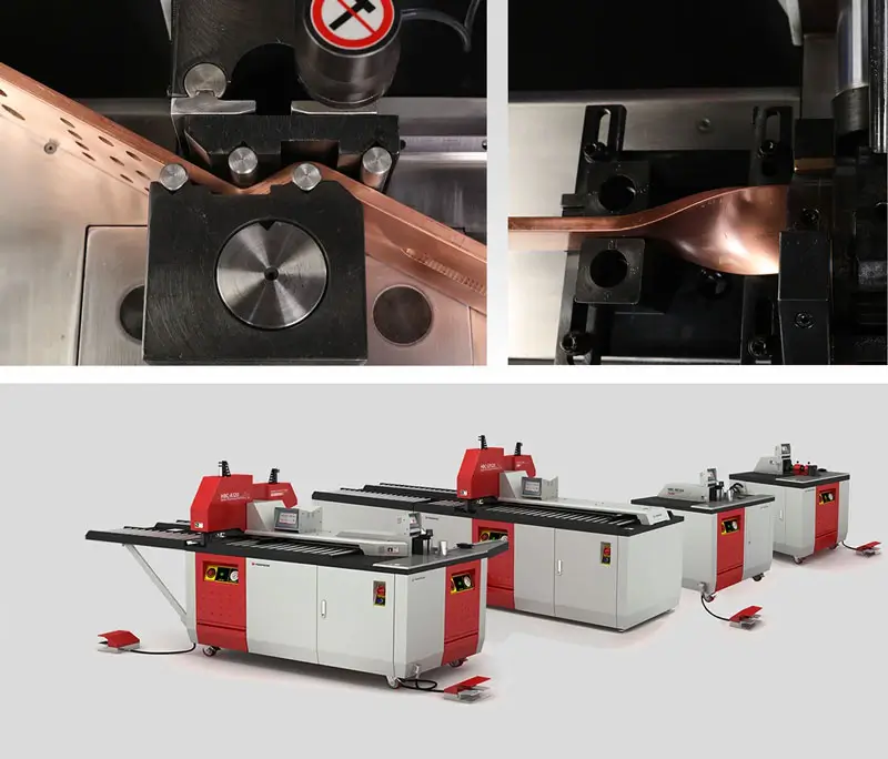
At PAYAPRESS, we build machines that cut, punch and bend busbars. EV projects follow a clear pattern: many identical cabinets, built fast and to tight tolerances. A busbar for EV charger cabinet assembly is often small, yet a hub programme may need hundreds of identical sets, so repeatability matters as much as accuracy.
Cutting comes first. Switchboard main bars often run 10 mm thick and 80–120 mm wide, while charger cabinet bars are thinner and more varied (typical; varies by design). A square, burr-free cut keeps contact faces flat, so bolted joints seat evenly. Punching follows. CNC punching places each hole pattern from a stored program. As a result, every bar in a run matches the drawing and the next cabinet (typical hole tolerance about ±0.1–0.2 mm; varies by machine).
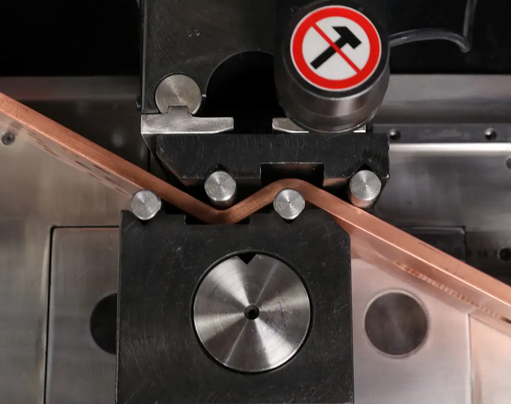
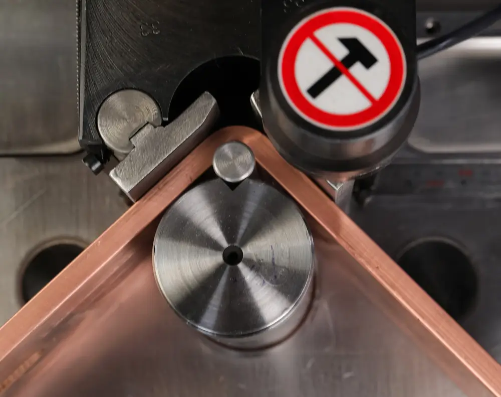
Bending is where repeatability is won or lost. Copper springs back after each bend, and the amount changes with temper and thickness, so the machine must compensate for it automatically. Modular cabinets add another demand, because offsets and edgewise bends must line up with terminals that leave no room for adjustment on the assembly line. Small angle errors also add up across a bar with several bends, so a part that looks right can still miss its far hole.
Finally, finishing and checking close the loop. Many charger bars are tin-plated to protect contact faces in humid outdoor cabinets (typical; varies by design). First-article inspection, stored programs and simple go/no-go fixtures then keep the thousandth bar identical to the first. As a result, modular, plug-and-play cabinets assemble quickly on the line and in the field. Reliable bars are a quiet but real part of EV charging power distribution.
Bend limits come from the material rather than the machine, so fabrication drawings should follow published data. The Copper Development Association lists a minimum bend radius of one bar thickness for copper and two for aluminum in its busbar ampacity tables.
Springback and minimum radii decide whether a bent bar matches its drawing. Our guide to bending copper busbar covers both in more detail.
Standards and Safety
So, what standards apply to EV charging distribution? Several IEC documents cover the chain, and most projects need more than one (check the current edition of each):
- IEC 61439-7: low-voltage assemblies for EV charging stations and similar public sites.
- IEC 61439-1 and IEC 61439-2: general rules and power switchgear assemblies for the LV switchboard.
- IEC 61439-6: busbar trunking systems.
- IEC 60364-7-722: low-voltage installations that supply electric vehicles.
- IEC 61851-1: general requirements for conductive charging systems.
- IEC 61851-23: DC electric vehicle supply equipment, including fast chargers.
- IEC 60529: degrees of protection (IP code) for enclosures.
In North America, NEC Article 625, UL 2202 for charging system equipment and UL 857 for busways cover similar ground. However, local rules and utility requirements still apply on top of these standards.
Outdoor equipment also needs the right outdoor IP rating, often IP54 or higher for cabinets and tap-off units (typical). In addition, protection against DC fault currents, clear isolation points and correct labelling keep each charging point safe to maintain. Public sites also face vandalism and vehicle impact, so barriers and robust enclosures belong in the design from the start.
Public sites need assemblies that ordinary people can use safely, so the switchboard standard deserves special attention. The IEC catalogue entry covers assemblies for EV charging stations up to 1,000 V AC or 1,500 V DC in its IEC 61439-7 summary.
Busbars themselves fall under several of these documents, from switchboards to trunking. For an overview of the key requirements, see our guide to busbar standards.
Conclusion: EV Charging Infrastructure
EV charging power distribution is now a system design task, not a wiring detail. Start with the grid connection, choose between cable, busbar trunking and a shared DC bus, and size for managed demand rather than nameplate totals. Then get the busbars right, from the switchboard to the DC link, and build them to repeatable tolerances. That approach lets a charging hub grow without rebuilding its backbone.
Getting the busbars right starts with the right material, rating and layout. Our busbar selection guide for LV panels covers those choices in detail.


Rate this article
Choose a rating from 1 to 5 stars.
No ratings yet