







If you’d rather listen than read, feel free to play the audio file below for the rest of this article.
Overview of International Busbar Standards
There is no single busbar standard. There is a stack of them, each answering a different question, and most confusion in this area comes from asking one document to do another one’s job.
Sort them into four layers. The assembly is governed by IEC 61439-1, which sets service conditions, characteristics and verification for the finished switchboard. Fault behaviour comes from IEC 60865-1, which handles the thermal and mechanical effects of short-circuit current. The metal itself is defined by EN 13601 in Europe and ASTM B187 in North America. Product families are covered regionally — IEEE and NEMA documents where North American switchgear sets the baseline.
One correction that saves arguments: IEC 60228 is a cable standard. It gives useful cross-sectional language, but it does not govern busbar dimensions and should not be cited as though it does.
For a comprehensive understanding of Power Distribution Systems, we highly recommend reviewing this article.
A practical note: DIN 46433 is still cited in legacy catalogs for flat copper bar dimensions, but DIN marks it as withdrawn, so current European work usually leans on EN 13601 plus project or manufacturer data.
Buy or preview IEC 61439-1 at the IEC webstore.
| Standard | Issuing Body | Scope |
|---|---|---|
| IEC 61439-1 | IEC | LV switchgear assembly definitions, service conditions, characteristics, and verification |
| IEC 60865-1 | IEC | Thermal and mechanical effects of short-circuit current on conductors |
| BS EN 13601 | BSI / CEN | Copper rod, bar, and wire for general electrical purposes |
| ASTM B187/B187M | ASTM | Copper bus bar, rod, and shapes for electrical applications |
| DIN 46433 | DIN | Legacy flat rectangular copper bar dimensional reference |
| IEEE C37.20.1 | IEEE | Metal-enclosed low-voltage power circuit breaker switchgear |
| NEMA PB 2 | NEMA | Deadfront distribution switchboards |
| IEC 60228 | IEC | Nominal conductor cross-sections and resistance values |
| IEEE C37.23 | IEEE | Metal-enclosed bus — the primary bus duct standard |
| UL 857 | UL | Busways — safety listing and testing |
| NEMA BU 1.1 | NEMA | Busway installation and handling practice |
Copper Busbar Marking and Phase Identification Standards
Bare copper has no insulation color, so identification has to be applied to the bar. Every governing standard requires it, and every one of them specifies something slightly different — which is why a panel that passes inspection in Dubai can fail one in Chicago.
Two rules cover the intent. IEC 60445 requires conductors to be identifiable by color or by alphanumeric marking. IEC 61439-1 pushes that requirement up to the assembly: the finished switchboard has to make phase, neutral and protective conductors unambiguous to anyone who opens it. BS 7671 adds that position at a busbar may itself indicate function, provided the identification leaves no room for doubt.
Phase colors by governing code. Check which column applies before you order sleeving.
| Conductor | IEC / BS 7671 (Current) | Old UK (Pre-2004) | NEC 208/120 V | NEC 480/277 V |
|---|---|---|---|---|
| L1 / A | Brown | Red | Black | Brown |
| L2 / B | Black | Yellow | Red | Orange |
| L3 / C | Grey | Blue | Blue | Yellow |
| Neutral | Blue | Black | White | Grey |
| PE / Ground | Green-and-Yellow | Green-and-Yellow | Green or Bare | Green or Bare |
Two traps worth knowing
First, the high leg. On a 4-wire delta system where one phase winding is center-tapped and grounded, NEC 110.15 requires the busbar or conductor with the higher voltage to ground to be permanently marked orange, at every point where a connection is made alongside the grounded conductor. NEC 230.56 repeats the requirement for service conductors. Note the collision: orange is also B-phase in a 480/277 V system, so orange means two different things depending on the supply. Never read it in isolation — test.
Second, phase arrangement is itself a standard. NEC 408.3(E) sets how busbars must be arranged in switchboards and panelboards: A, B, C in order from front to back, top to bottom, or left to right when viewed from the front. Getting the colors right on bars that are physically in the wrong order does not make the assembly compliant.
How the marking is applied
On bare bar the practical options are heat-shrink sleeving in the phase color, phase-identification tape at accessible points, applied paint (still common on substation and large distribution bars), or engraved and riveted tags. Whichever you use, it must survive the assembly’s service temperature and remain legible for the life of the panel — a marker that fades in three years fails the intent of the rule even if it was correct on day one.
Material marking is a separate thing. Buyers sometimes mean grade identification rather than phase identification: the ETP C11000 designation, heat or cast number, and EN 13601 or ASTM B187 conformance. These normally travel on the mill certificate rather than being stamped on every bar. If your project requires bar-level traceability, specify it at order stage — it is not a default.
IEEE and NEMA Standards for Bus Ducts and Metal-Enclosed Bus
Where a project follows North American practice, a different set of documents applies — and the one most often cited incorrectly is IEEE C37.20.1, which covers metal-enclosed switchgear, not busway.
| Standard | Body | Scope |
|---|---|---|
| IEEE C37.23 | IEEE | Metal-Enclosed Bus — The Primary Bus Duct Standard |
| UL 857 | UL | Busways — Safety Listing and Testing |
| NEMA BU 1.1 | NEMA | Busway Installation and Handling Practice |
| IEEE C37.20.1 | IEEE | Metal-Enclosed LV Power Circuit Breaker Switchgear |
| NEMA PB 2 | NEMA | Deadfront Distribution Switchboards |
There is no such thing as an “IEEE certified” copper bar. IEEE publishes design and test standards for the assembly. The bar itself is certified against a material standard — ASTM B187 in North America, EN 13601 in Europe. If a specification asks for IEEE-compliant bus, it is asking about the enclosed system, not the conductor.
Copper Busbars—Properties, Grades, and Applications
Copper remains the default current-carrying conductor in switchboards because it combines high conductivity, compact cross-section, stable joints, and good corrosion behavior. CDA data uses 100% IACS copper at about 58 MS/m, which is why copper busbar capacity stays strong in tight panel spaces.
ASTM B187 lists common electrical copper grades for bus applications, including OFE, OF, and ETP. In practical panel work, ETP copper C11000 is the standard choice because it balances conductivity, availability, fabrication ease, and cost.
Oxygen-free copper grades such as C10200 are chosen when purity, vacuum service, or elevated-temperature joining matters more than commodity cost. Silver-bearing copper is a niche upgrade when joint stability at higher service temperatures becomes the design driver.
Copper also handles forming and bolted jointing well. Compared with aluminum, the copper design guide notes better resistance to mechanical damage, better beam stiffness, lower thermal expansion, and fewer long-term issues from cold flow in clamped joints.
Read Copper Development Association (CDA) guide to Ampacities and Mechanical Properties of Rectangular Copper Busbars.

Standard Busbar Sizes: Dimensions, Sections and Indicative Ratings
Two different questions get asked here and they need separate answers. What sizes can I buy? is a stock and tolerance question, answered by EN 13601 and your supplier’s range. What current will it carry? is a thermal question that no dimension table can answer on its own.
Standard flat bar sizes commonly stocked:
| Thickness | Common Widths Available (mm) |
|---|---|
| 3 mm | 12, 15, 20, 25, 30, 40 |
| 5 mm | 20, 25, 30, 40, 50, 60, 80, 100 |
| 6 mm | 30, 40, 50, 60, 80, 100, 120 |
| 10 mm | 40, 50, 60, 80, 100, 120, 160 |
| 12 mm | 60, 80, 100, 120, 160, 200 |
Specifying outside this grid is possible but costs more and takes longer, because mills roll standard sections in volume and custom sections to order. Where layout allows, designing to a stocked size is one of the cheapest decisions available.
For engineers searching busbar current carrying capacity table by cross section, standard stock sizes are useful only as a first pass. EN 13601 defines electrical copper bar sizes and tolerances, while copper ampacity tables estimate current based on emissivity, temperature rise, and installation condition.
The values below are indicative free-air references near the ranges commonly published for rectangular Copper No. 110 bars. Final busbar rating must be derated for enclosure heating, bar grouping, orientation, surface finish, and allowable conductor temperature.
Preview a sample extract of EN 13601.
| Width × Thickness (mm) | Cross Section (mm²) | Approx. Current Capacity (A) |
|---|---|---|
| 20 × 3 | 60 | 215 |
| 25 × 3 | 75 | 260 |
| 30 × 5 | 150 | 420 |
| 40 × 5 | 200 | 540 |
| 50 × 5 | 250 | 660 |
| 60 × 5 | 300 | 760 |
| 80 × 6 | 480 | 1050 |
| 100 × 10 | 1000 | 1600 |
These are free-air references only. Every one of them drops inside an enclosure — see our busbar sizing guide for the derating factors and the verification sequence.
Aluminum Busbars — Properties, Grades, and Applications
Aluminum is a credible power rail material when weight and material cost matter more than compactness. Copper design data shows aluminum at roughly 61% IACS, so an equivalent-resistance aluminum busbar usually needs about 1.6 times the copper cross-section.
That trade-off is attractive because density flips in aluminum’s favor. Typical values are about 8.96 g/cm³ for copper and 2700 kg/m³ for aluminum, so an equivalent-rated aluminum conducting bar can cut weight dramatically even when the section gets larger.
For material selection, 1350 remains the baseline electrical-conductor alloy, while 6101 is widely used for bus bars because it adds workable strength and machinability. 6063 also appears in electrical applications where extrudability and surface finish matter.
The downside is joint sensitivity. Aluminum has higher thermal expansion, forms oxide quickly, and tolerates poor workmanship less than copper, so joint preparation, torque control, and inspection matter more over service life.
Download the full Alloy 6101 document.
Aluminum Busbar Jointing and Contact Considerations
If you ask copper vs aluminum busbar which is better for switchgear, the practical answer often turns on joints, not bulk conductor properties. CDA notes that direct copper-aluminum contact in the presence of moisture can drive galvanic reaction unless a compatible interface such as tin is used.
That is why aluminum terminations often use tinned interfaces, bimetallic transition hardware, anti-oxidant compound, and disciplined torque practice. The same sources also warn that oxide re-formation and creep can raise contact resistance over time if the connection is poorly prepared or maintained.
Copper vs Aluminum Busbar—Direct Comparison
Copper wins where compactness, joint simplicity, mechanical strength, and lower expansion matter. Aluminum wins where low weight and lower raw material cost matter, especially in large distribution runs where space is available.
The comparison is not copper good, aluminum bad. It is compact vs lightweight, simple jointing vs more careful jointing, higher conductivity vs lower material cost, and lower expansion vs larger section.
For critical LV switchgear, copper still dominates because it reduces busbar cross-section, improves stiffness, and lowers the risk of long-term connection drift.
For busbar Arrangements or large power distribution, aluminum can be the rational engineering choice.
The right decision is made at system level, not kilogram price alone. Installation labor, maintenance access, corrosion exposure, short-circuit duty, and panel footprint usually shift the true lifecycle answer.
Access the Copper for Busbars Guidance for Design and Installation reference document.
| Property | Copper Busbar | Aluminum Busbar |
|---|---|---|
| Electrical Conductivity | ~58 MS/m (100% IACS baseline) | ~34–35 MS/m (~61% IACS) |
| Required Cross-Section for Same Current | Baseline | ~1.6× copper |
| Density | 8.9 g/cm³ | 2.7 g/cm³ |
| Weight for Equivalent Rating | Heavier | Roughly half the weight |
| Material Cost | Higher | Lower |
| Jointing Complexity | Simpler | More preparation-sensitive |
| Corrosion / Oxide Behavior | Strong general resistance | Oxide layer forms rapidly |
| Thermal Expansion | Lower | Higher |
| Mechanical Strength / Stiffness | Higher | Lower, often offset by larger section |
| Typical Use | Compact LV panels, critical switchgear | Large distribution, weight-sensitive runs |
| Recyclability | High | High |
Material choice is only one input. Space, service access, environmental severity and the project’s governing standard usually shift the answer more than conductivity does — our busbar selection guide for LV panels works through the full decision framework.
Busbar Sizing Methodology—Step by Step
Standards define what must be verified, not how to calculate it. The sequence below is the order the checks have to happen in — each step is worked through in full in our busbar sizing guide.
- Set continuous current. Start from design load, diversity, duty cycle, and future margin.
- Pick a trial section. Use a standard busbar cross-section from published tables or tested systems.
- Apply derating. Correct for enclosure heating, ambient, bar grouping, and mounting orientation.
- Check temperature rise. Verify the strip conductor stays within the assembly’s accepted limits.
- Verify fault duty. Continuous current and short-circuit withstand capacity are not the same check.
- Confirm mechanics. Support spacing, electromagnetic force, and deflection must remain acceptable.
Short-Circuit Withstand Rating — Thermal and Mechanical
Two separate checks apply. Thermal withstand asks whether the conductor survives the fault duration without exceeding its allowable temperature. Mechanical withstand asks whether peak electromagnetic force bends the bar or overloads its supports. Both are calculated under IEC 60865-1, and in high-fault installations either one can govern sizing more strictly than continuous ampacity. The calculation method is worked through in our busbar short-circuit withstand guide.
Surface Treatment and Plating Standards for Busbars
Surface finish affects contact resistance, oxidation behavior, and maintenance interval. IEC 61439 links conductor suitability to the contact system and surface treatment, which is why bare vs plated is a genuine design choice, not a cosmetic one.
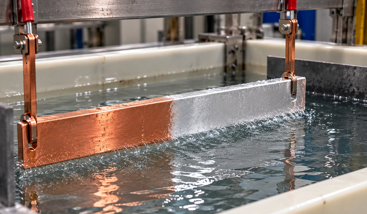
Bare copper is still common for general bolted joints in clean indoor assemblies. Tin-plated bars are widely used where oxidation control, solderability, and stable low-resistance joints matter more than raw material simplicity.
Silver plating is favored at demanding contact points because it preserves low contact resistance and performs well at elevated temperature. Nickel plating is more of a harsh-environment or wear-resistant choice than a default low-voltage switchgear finish.
For aluminum, plating and interface treatment are even more important because oxide management dominates joint reliability. Tin, silver, and nickel are all used selectively, depending on connection duty and environment.
See the research from Electris Coating Systems on Precision busbar plating services for manufacturers.
| Surface Finish | Material | Typical Purpose | Common Reference Context |
|---|---|---|---|
| Bare (unplated) | Copper | General indoor bolted joints | IEC 61439 assembly verification |
| Tin-plated | Copper or Aluminum | Oxidation control, improved contact, solderability | IEC 61439 projects and common industrial practice |
| Silver-plated | Copper | High-performance contact zones, elevated temperature joints | Critical low-resistance connections |
| Nickel-plated | Copper or Aluminum | Aggressive or polluted environments, harder surface | Project or environmental specification |
IEC Standards for Busbar Sizing: What They Cost and What Is Free
A common search behind this topic is for a free PDF of the governing standard. It is worth being straight about what exists.
IEC and EN standards are copyrighted and sold. There is no legitimate free full copy of IEC 61439-1, IEC 60865-1 or EN 13601. What is free is the preview: the IEC webstore publishes the scope, contents and a sample extract of every standard at no charge, which is often enough to confirm whether a document covers your question before you buy it. National adoptions through BSI, DIN or SIST sometimes publish longer sample extracts via resellers.
What is genuinely free and genuinely useful for busbar sizing:
| Document | Publisher | Covers | Cost |
|---|---|---|---|
| Copper for Busbars: Guidance for Design and Installation | Copper Development Association | Ampacity, Joints, Mechanical Properties, Plating | Free PDF |
| Guide to Verification of Temperature Rise and Short-Circuit Withstand | BEAMA | How to Verify Without Testing; Routes to IEC 60865-1 | Free PDF |
| Alloy Data Sheets (1350, 6101, 6063) | Extruders Such as Hydro | Aluminum Conductor Alloy Properties | Free PDF |
| IEC 61439-1 Preview | IEC | Scope and Contents Only | Free |
| IEC 61439-1 (Full) | IEC | The Governing LV Assembly Standard | Paid |
| EN 13601 (Full) | CEN / BSI | Copper Bar Material and Tolerances | Paid |
The practical route for most panel builders: work from the CDA and BEAMA documents for calculation method, buy IEC 61439-1 once because you will reference it constantly, and rely on supplier mill certificates rather than buying EN 13601 yourself.
Conclusion
Busbar standards come down to one disciplined habit: never separate material choice from verification. The correct bus bar is the one that satisfies current, temperature, short-circuit, connection, and maintenance requirements together.
Copper is usually the safer answer for compact switchgear and demanding joints. Aluminum becomes compelling when weight and material economy justify a larger cross-section and a more controlled connection strategy.
Use standards the right way: IEC 61439 for the assembly, IEC 60865 for short-circuit effects, and EN 13601 or ASTM B187 for copper material definition.
When in doubt, trust verified assembly data over a single ampacity table. Free-air vs enclosed, vertical vs horizontal, and bare vs plated all shift the real operating margin more than many first-pass estimates suggest.



Rate this article
Choose a rating from 1 to 5 stars.
No ratings yet