







If you’d rather listen than read, feel free to play the audio file below for the rest of this article.
Power Factor: Quick Answers
What is power factor? The ratio of real (active) power to apparent power: PF = P / S. Not voltage × current, and not current ÷ resistance.
What is the power factor symbol? Power factor is normally written PF or cos φ. In IEC terminology the symbol λ (lambda) denotes the total power factor, while cos φ strictly means the displacement power factor — the part caused by phase shift alone, ignoring harmonics.
Does reactive power do any work? No. Reactive power performs no useful work. It flows back and forth between the source and the load’s magnetic or electric field. It is measured in VAR, not watts, and it sits 90° out of phase with real power — never in phase with it. Reactive power is caused by energy storage in inductance and capacitance, not by harmonics. (Harmonics reduce power factor by a separate mechanism: distortion.)
What happens when power factor is low? Line current increases and energy costs rise. For the same real power, current scales as 1/PF — so a load at PF 0.7 draws about 43% more current than the same load at PF 1.0. That extra current produces extra I²R heating, extra voltage drop, and usually a reactive-power penalty on the bill. Low power factor does not eliminate reactive power and it does not reduce losses.
What is reactive factor? The counterpart of power factor: sin φ = Q / S. Where power factor tells you the useful fraction of apparent power, reactive factor tells you the non-working fraction.
Power Factor Formula: P, Q and S Defined
Power factor is defined as the ratio of active power to apparent power:
PF = P / S = cos φ
Three quantities are involved, and confusing them is the most common source of error in compensation calculations. In a linear AC circuit they form a right triangle, where S² = P² + Q².
In loads (consumers), three types of power are defined: apparent power (S), active power (P), and reactive power (Q). Active power is the real power and the power of resistive loads, shown in watts (W). Reactive power is an imaginary power defined to compare the power of inductors and capacitors, and apparent power is the vector sum of active and reactive power. If the reactive power of a capacitor increases, the energy required to charge and discharge it increases, but ultimately it does not consume it. This power is expressed in kVAR.
Let’s explain this concept with a cup of cappuccino. You have a cup of cappuccino. The part of the cup filled with coffee is the real power or active power. The part filled with cream or foam is reactive power, which is usually not fully consumed, and the entire cup is apparent power. You pay for the whole cup, but in practice you do not consume the cappuccino foam.
Table 1 — Types of Power in AC Electrical Systems
| Type of Power | Symbol | Unit | Does Useful Work? | Definition |
|---|---|---|---|---|
| Active (Real) Power | P | W / kW | Yes | The power that performs useful work — turns motors, produces heat and light |
| Reactive Power | Q | VAR / kVAR | No | Oscillates between source and load’s magnetic or electric field; occupies network capacity without being consumed |
| Apparent Power | S | VA / kVA | Partly | The vector sum of active and reactive power: S = √(P² + Q²) — what the network must actually be sized for |
The Three Types of Power Factor: Unity, Lagging and Leading
“Types of power factor” is asked in two different senses, and both deserve an answer.
By phase relationship, there are three types:
- Unity power factor (PF = 1). Current and voltage are exactly in phase. The load is purely resistive — heaters, incandescent lamps, resistive furnaces. All apparent power is real power.
- Lagging power factor (current lags voltage). The load is inductive: motors, transformers, welding sets, fluorescent ballasts. This is the normal condition in industrial plants, and it is what capacitor banks exist to correct.
- Leading power factor (current leads voltage). The load is capacitive, or the plant is over-compensated. Leading power factor is not “better” than lagging — it raises busbar voltage, can cause self-excitation problems, and many utilities penalise it just as they penalise lagging.
By cause, power factor also splits into three components:
- Displacement power factor (cos φ). The part caused by phase shift between fundamental voltage and current. This is what a capacitor bank corrects.
- Distortion power factor. The part caused by harmonic current, which draws extra RMS current without contributing real power. A capacitor cannot correct this — it makes it worse. Distortion needs filters or active correction.
- True (total) power factor. The product of the two. This is the number that actually determines your current and your bill.
The distinction matters commercially. A plant full of variable-speed drives can show cos φ near 1.0 on a basic meter while its true power factor is 0.75, because the meter reads displacement only. Installing capacitors in that plant will not help and may cause resonance.
How to Read Power Factor from a V-I Trajectory
A V-I trajectory plots instantaneous current against instantaneous voltage over one full cycle, instead of plotting both against time. The shape it traces is a compact signature of the load, and power factor can be read directly off it.
Straight diagonal line through the origin. Current is exactly proportional to voltage at every instant, so they are in phase. PF = 1, purely resistive load.
Ellipse. The load is reactive and linear. The wider the ellipse opens, the lower the power factor. A narrow, near-diagonal ellipse means high PF; a fat one means low PF.
Circle. The extreme case of an ellipse — voltage and current are 90° apart. PF ≈ 0, purely reactive load.
Direction of travel. For a lagging (inductive) load the trajectory is traced in one rotational direction; for a leading (capacitive) load it reverses. The shape alone cannot distinguish inductive from capacitive — you need the direction.
Distorted, pinched or looped shapes. The load is non-linear — a rectifier, switch-mode supply, LED driver or variable-speed drive. Harmonic current is present, so the true power factor is below the displacement power factor no matter how narrow the ellipse looks.
The formula for a linear load. For a clean ellipse you can extract the phase angle exactly. Read the current value where the trajectory crosses the vertical axis (the current at the instant voltage is zero), call it i₀, and read the peak current I_m. Then:
sin φ = i₀ / I_m, so PF = cos φ = √(1 − (i₀ / I_m)²)
Worked example: if the trajectory crosses zero voltage at 30 A and peaks at 50 A, then sin φ = 0.6, φ = 36.9°, and PF = 0.8 lagging or leading depending on the direction of travel.
This method only holds for linear loads. If the trajectory is not a clean ellipse, the waveform contains harmonics and the ellipse geometry no longer maps to a single phase angle — you need harmonic measurement instead.
The Vector Concept of Apparent and Reactive Power, and the Definition of Leading and Lagging
As we said, apparent power is the vector sum of active and reactive power. Let’s examine the vector concept of power.
A circuit with a resistive load has current and voltage waveforms in phase, but in a circuit with a reactive load (capacitive or inductive), the inductor and capacitor do not consume power but occupy network capacity because they draw current. A capacitor’s current leads the applied voltage by 90°, so a capacitor is a source of reactive power. An inductor’s current lags by 90°, so an inductor is a consumer of reactive power. This opposition is the entire basis of capacitor-based compensation. In the waveform of a capacitive load, the current leads the voltage. Inside the different types of electrical power distribution board, resistive and reactive loads sit side by side, and the combination of their active and reactive power components is what we call total or apparent power, shown in kilovolt-ampere (kVA).
So a phase difference is created between voltage and current, and in fact both parameters are vector quantities. Since power is the product of voltage and current, power is also a vector quantity. If the angle between the voltage and current of the load decreases (power factor increases), the amount of active power consumed becomes closer to apparent power, and therefore the reactive power consumed decreases. One method to correct this angle is using a capacitor bank, which we will discuss further below.
Why Power Factor Compensation Matters: Losses, Capacity and Cost
Most national grid operators regulate power factor, either through minimum thresholds written into supply agreements or through reactive-energy charges on the bill. The exact rules vary by country, but the underlying logic is universal: reactive current uses network capacity that the utility has to build and maintain, without delivering any billable energy.
To the extent that the power factor of consumers increases, the current passing through the network (for a constant consumed power) will decrease, which causes reduced losses, reduced voltage drop, and increased capacity of lines, transformers, and so on. On the other hand, by managing electricity tariffs, consumers can be guided toward consumption during hours when the cost of consumed energy is lower (light load).
Here, we examine the necessity and methods of power factor correction, as well as electricity tariffs, in order to free capacity in distribution and transmission networks and also reduce the cost of energy consumed by subscribers.
Most electrical devices and consumers require some reactive power to provide the necessary conditions to perform useful work. For example, an electric motor, to convert electrical energy into mechanical energy, needs to generate magnetic flux in the motor air gap and cannot create electromotive force without reactive power.
Also, power electronics systems, voltage stabilizers, induction and electric arc furnaces, AC and DC welding systems, unbalanced load balancers, equipment with nonlinear characteristics, and so on require reactive power. But this power adds network current and, as a result, causes voltage drop and increases power losses along the path as heat. Among the losses imposed on the network in this state are:
- Adding generator current and the need for generators with higher power
- Increasing network current (need for cables with larger cross-sectional area)
- Power loss in distribution networks (heat generation and voltage drop)
So we must know what power factor means exactly and what effect it has in the system. Then we must understand power factor correction methods and the equipment required for compensation.
Reactive Energy Tariffs and the 0.9 Power Factor Threshold
In calculating the energy price, maximum demand and active and reactive energy are considered separately. In most contracts, the maximum reactive consumption is considered equal to 50% of active consumption.
Reactive consumption is subject to cost if it is more than 50% of active consumption, which corresponds to a power factor of 0.9. It is recommended that a higher number such as 0.92 be considered for calculation so that we have reserved capacitive capacity. The 0.9 threshold is not arbitrary. If reactive consumption equals 50% of active consumption, then tan φ = Q/P = 0.5, giving φ = 26.6° and cos φ = 0.894 — which rounds to 0.9. Designing to 0.92 rather than exactly 0.9 leaves reserve capacitive capacity so that normal load variation does not push you back across the billing threshold. Tariff structures differ by country, so confirm the local rules before sizing.
Demand Tariffs and Maximum Demand Charges
In this case, the basis of consumption is the customer’s maximum power consumption during a specific month. If apparent power, not active power, is the basis, it is noted that you should select the capacitor amount so that cos φ = 1 becomes the target.
Capacitor Types for Power Factor Compensation: LV and MV
Power factor correction capacitors fall into two families, split by system voltage. The construction, the failure mode and the governing standard all differ between them.
Table 2 — Low-Voltage vs Medium-Voltage Capacitors
| Feature | Low-Voltage Capacitor | Medium-Voltage Capacitor |
|---|---|---|
| Voltage range | Up to 1000 V | Above 1000 V |
| Construction | Dry, self-healing metallised film | Oil or resin filled, non-self-healing |
| Connection | Single-phase or three-phase, usually delta | Single-phase or three-phase, delta or star |
| Capacitor standard | IEC 60831-1/-2 (self-healing), IEC 60931-1 (non-self-healing) | IEC 60871-1 |
| Bank / assembly standard | IEC 61921, applied together with IEC 61439-1 and -2 | IEC 60871-1 with the relevant switchgear standard |
| Typical application | Industrial LV panels, local motor correction | Transmission and distribution substations |
Two points that catch people out. First, IEC 60143 is for series capacitors, not shunt power factor correction — it is frequently miscited in this context. Second, an LV correction bank is not just a box of capacitors: IEC 61921 is intended to be used alongside IEC 61439-1 and IEC 61439-2, which means your capacitor panel is a low-voltage assembly and must satisfy the same verification requirements as any other — temperature rise, clearances, short-circuit withstand. The responsibilities and verification routes under IEC 61439 apply in full.
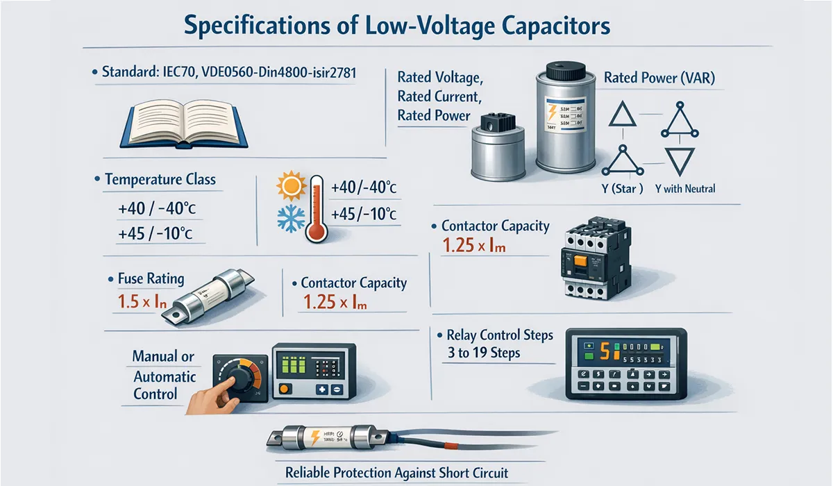
Specifications of Low-Voltage Capacitors
- Applicable standards: IEC 60831-1 and -2 for the capacitor units, IEC 61921 for the correction bank, IEC 61439-1/-2 for the assembly. EN 60831-1 is the harmonised European equivalent.
- Rated voltage, rated current, rated power (VAR capacity), active losses, ambient temperature, cooling temperature, maximum and minimum capacitor operating temperature, type of connection to the network
- The temperature class for maximum and minimum operating temperature of the capacitor is +40/−40, +40/−20, +40/−10, +45/−10.
- A three-phase capacitor can be connected as Y (star), Δ (delta), Y (star with neutral point), lll (three sections without internal connections).
- The power of a three-phase capacitor unit must be stated as the sum of the three-phase power.
- The capacity of the fuse switch installed in the capacitor feeder path must be 1.5 times the capacitor current.
- If a contactor is used, its capacity (after applying thermal coefficients) is 1.25 times the maximum resulting current.
- For more reliable protection of the capacitor against short circuit, HRC fuses or a factor of 1.5 times the rated capacitor current is used.
- At low voltage and very small loads, power adjustment by manual control is possible.
- For automatic control and adjustment of active power, active power measuring relays, current-sensitive relays, or timers can be used.
- In small industrial consumers and also group compensators, using a current relay is better.
- In a uniform and predictable load, a time relay can be used. The best control method is a relay sensitive to reactive power. The capacitor steps can be programmed from 3 to 19 steps. The value of each step and the number of steps depend on load conditions.
Table 3 — Standard Industrial Capacitor Ratings (kVAR)
| # | Rating (kVAR) | Common Application | Voltage Class |
|---|---|---|---|
| 1 | 5 | Small motors, local compensation | LV |
| 2 | 10 | Small to medium loads | LV |
| 3 | 12.5 | Small industrial loads | LV |
| 4 | 15 | Medium-duty motors and equipment | LV |
| 5 | 20 | Small to medium industries | LV |
| 6 | 25 | Central LV panels | LV |
| 7 | 30 | Heavy industrial loads | LV |
| 8 | 40 | Large industrial loads | LV |
| 9 | 50 | Industrial plants | LV |
| 10 | 60 | Distribution substations | LV |
| 11 | 100 | Large central compensation banks | LV |
Capacitor Bank Fuse Sizing and Overcurrent Protection
Capacitor circuits need HRC (high rupturing capacity) fuses because a capacitor draws current continuously at rated kVAr, tolerates a permanent overcurrent from capacitance tolerance and harmonics, and must survive a very large inrush at every switching operation. An ordinary fuse sized on nameplate current will nuisance-blow within days.
Fuse rating: 1.5 to 2.0 × the rated capacitor current. The margin covers three things at once — the capacitance tolerance allowed by the standard, the permitted overvoltage, and harmonic current drawn by the capacitor at frequencies above the fundamental. Many suppliers specify 1.65× as a working default.
Worked example. A 150 kVAr, 400 V, three-phase capacitor draws a line current of 150,000 / (√3 × 400) = 217 A. At 1.65× that gives 358 A; at 2.0× it gives 434 A. Select a 400 A HRC fuse.
Two cautions. If the bank has detuned reactors, the reactor’s maximum permissible current becomes the governing limit and the multiplier is reduced accordingly — check the reactor datasheet, not just the capacitor’s. And fuses protect against short circuit; they do not protect against sustained harmonic overload. That requires either detuned reactors or an overcurrent relay set around 1.3× rated.
Discharge Resistors: The 75 V in 3 Minutes Rule
To reduce the voltage across power factor correction capacitors after they are taken out of the circuit, resistors connected to the capacitor terminals are used. The value of these resistors varies depending on the capacitor power.
This resistor must be able to reduce the voltage within 3 minutes after disconnecting the capacitors to a low-risk level (below 75 V). In special cases where the capacitor is directly connected to the motor windings, there is no need for a discharge resistor, and contact with the live parts of the capacitor must be avoided until the motor comes to a complete stop. According to the standard, capacitors must be charged to a maximum of 10% of the rated voltage for reconnection to the circuit.
The discharge resistor is calculated by the manufacturer based on the capacitor power and is connected to the capacitor during unit construction. Also, the discharge time is specified on the capacitor nameplate. In cases where fast discharge of the capacitor is needed for switching into the circuit, a fast discharge circuit is used instead of a resistor.
Thyristor Switching for Fast Power Factor Correction
In cases where power factor changes are rapid, a thyristor switch should be used instead of a capacitor contactor. These parts, together with a fast discharge circuit, are connected to the capacitor and can insert the capacitor into the circuit 5 milliseconds after it is taken out of the circuit.
Power Factor Regulators: Step Control and Measurement
In addition, by using an intelligent regulator, a lot of information can be obtained from the circuit much more easily. The intelligent regulator for managing capacitor banks is designed and manufactured in two models, 6-step and 12-step. Advantages of the intelligent regulator include control and measurement of voltage, power, load current, reactive current, voltage harmonic distortion, cos φ, capacitor connection steps, the number of capacitor switching operations, recording the date of alarms, and measuring the ambient temperature inside the electrical panel.
This device measures the load power factor and inserts the required capacitor amount (step-by-step) into the circuit. In other words, by measuring the consumer voltage and current, the power factor is calculated, and considering the desired power factor (usually 0.9), the required reactive power is calculated. The regulator output, in proportion to this reactive power, inserts suitable steps (or removes them from the circuit).
If the total capacitive reactive load is Q, it can be divided into small steps q. Increasing the number of steps helps the accuracy of the result, but the number of contactors and other equipment increases and causes higher cost.
Capacitor-Duty Contactors: Why Standard Contactors Fail
Another important piece of equipment in this method of power factor correction is the capacitor contactor. Due to the very high current of capacitors (at switching-on), using ordinary contactors causes the contacts to be destroyed in less than their useful lifetime.
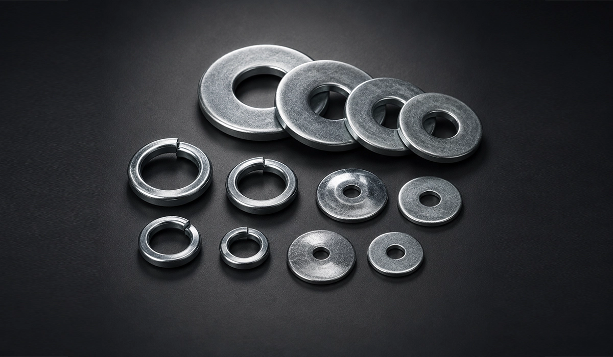
To insert each capacitor of the capacitor bank into the circuit, a capacitor contactor is used. The capacitor contactor can be controlled by the intelligent regulator. For example, if we have 9 capacitors of 25 kVAR, 9 capacitor contactors and one 8-step regulator are used. For each capacitor, a separate fuse must be used, and only one control circuit can be used for the capacitor bank. Every step lands on the same shared node, so the bar the contactors feed from is a terminal bus bar carrying the full bank current — it must be sized for the continuous load and torqued for the repeated inrush.
First, two capacitors enter the circuit, and the next capacitors are added in pairs, and after capacitors 1 and 2 enter the circuit, capacitors 3 through 8 enter the circuit one by one in order.
How Power Factor Compensation Works in Plain Language
Power factor correction is a technique to reduce the negative effects of reactive loads in an AC power network. But as stated, the load needs reactive power. Therefore, the reactive power required by the consumer must be supplied by a way other than the network, because increasing reactive power generation in power plants increases generator excitation current, which faces dynamic limitations.
Power factor is usually a number between zero and one, where one and values close to it are considered desirable. Correction or reduction of the power factor leads to increased losses. The lost power at a power factor less than one indicates reactive power. Reactive power leads to increased overload and increased electricity costs. Inductive loads and harmonics are among the reasons for a reduced power factor.
During power factor correction, instead of the network supplying inductive current (lagging current), by using a capacitor in parallel, the required current is supplied by the capacitor. A capacitor’s current leads its voltage by 90°; an inductor’s current lags by 90°. Because they are exactly opposite, a capacitor placed in parallel with an inductive load can supply the reactive current that the motor needs, locally. The reactive energy then oscillates between the capacitor and the motor instead of travelling back and forth from the supply. The network current drops to the real-power component, while the motor still gets all the magnetising current it requires. This action is called power factor correction.
When the capacitor is charged, the inductor is discharged, and vice versa. The inductor and capacitor supply each other’s current. The power factor correction triangle shows the required capacitive capacity to change the correction angle, or in other words the PF angle from Φ1 to Φ2.
The current in a capacitor connected to AC, unlike an inductor, has a 90-degree phase lead and therefore, while neutralizing the inductive effect of the consumer, does not draw any real power from the network. To insert capacitors into the circuit in the required amount, the capacitor regulator and capacitor contactor help.

How to Measure Power Factor in an Electrical Panel
As stated, from the cosine of the phase angle difference between current and voltage, the apparent and effective components of powers, voltages, and currents can be calculated. In electrical devices, power factor is often written for full load. Since the network is designed for a specific apparent power, the attempt is to keep the apparent power as low as possible. If suitable capacitors are installed in parallel and next to the consumer, part of the reactive power oscillates between the capacitor and the consumer, and the remainder is drawn from the network, which reduces the reactive loading of the network. If by compensation the power factor reaches one, only effective current will exist in the network.
The ammeter and power measuring device are often installed in the main panel. Clamp meters can also be used. The required measurements are performed in the incoming feeder or outgoing feeders of the main substation.
Simultaneous measurement of network voltage improves calculation accuracy. However, the rated voltage can be considered 380 or 400 volts. From voltage (U), apparent current (Is), and power factor, active power can be calculated.
To obtain Qc, the reactive power taken from the capacitor is obtained from the difference between reactive power Q1 before compensation and Q2 after compensation. Therefore:
Qc = Q1 − Q2
Capacitor Bank Sizing: How Much kVAr Do You Need?
When designing power factor correction capacitors, a list of loads must be prepared, and the power factor of each load must be read along with the active power consumption, which is usually written on all devices. Then the consumed kVA is calculated, and by dividing the total active power by the apparent power, the overall power factor is obtained. Then the capacitor value is calculated according to the tables available in the catalog. Typically, the capacitor bank is designed 20% higher than the obtained number.
Calculating Capacitor Power at Different Power Factors
A) With available and desired power factors and reactive power, we have:
- Qc: capacitor power in kVAR
- P: active power of equipment in kW
- tanφ1: existing power angle coefficient
- tanφ2: desired power angle coefficient
Formula: Qc = P × (tanφ1 − tanφ2)
B) Through the electricity bill of the unit:
The information on the bill includes: consumed active power and consumed reactive power.
Worked Example: Calculating Real Power and Required kVAr
A three-phase plant draws 250 A at 400 V with a measured power factor of 0.9 lagging. Find the real power and the capacitors needed to reach 0.95.
Apparent power: S = √3 × 400 × 250 = 173.2 kVA
Real power: P = S × cos φ = 173.2 × 0.9 = 155.9 kW
Reactive power now: Q₁ = P × tan φ₁ = 155.9 × 0.4843 = 75.5 kVAr
Reactive power at target: Q₂ = 155.9 × 0.3287 = 51.2 kVAr
Capacitors required: Qc = Q₁ − Q₂ = 24.3 kVAr
Round up to the next standard step size and add the customary 20% design margin for load growth. Table 4 gives the same answer directly: from 0.90 to 0.95 the factor is 0.156 kVAr per kW, and 155.9 × 0.156 = 24.3 kVAr.
Table 4 — Capacitor Correction Factor (kVAr per kW) to Reach Target Power Factor
| Existing PF ↓ / Target PF → | 0.85 | 0.90 | 0.92 | 0.95 | 1.00 |
|---|---|---|---|---|---|
| 0.60 | 0.714 | 0.849 | 0.907 | 1.005 | 1.333 |
| 0.65 | 0.549 | 0.685 | 0.743 | 0.840 | 1.169 |
| 0.70 | 0.400 | 0.536 | 0.594 | 0.692 | 1.020 |
| 0.75 | 0.262 | 0.398 | 0.456 | 0.553 | 0.882 |
| 0.80 | 0.130 | 0.266 | 0.324 | 0.421 | 0.750 |
| 0.85 | — | 0.135 | 0.194 | 0.291 | 0.620 |
| 0.90 | — | — | 0.058 | 0.156 | 0.484 |
Values are tan φ₁ − tan φ₂, in kVAr per kW of load. Multiply by your real power in kW.
What Is the C/K Setting on a Power Factor Regulator?
This coefficient is given to the regulator to set the interval between inserting the capacitor and removing it from the circuit. In fact, this ratio indicates the ratio of the conversion of the first capacitor step power (C) to the conversion ratio of the current transformer connected to the regulator (K).
For example, if the power factor drops below 89%, it inserts a capacitor step into the circuit, and if cos φ becomes greater than 0.935, it removes one step from the circuit. C is the capacity of the first capacitor step installed in the circuit, and K is the CT ratio.
- If capacitor power is less than 500 VAR, its value is expressed as capacitor capacitance (C).
- If capacitor power is more than 500 VAR, its value is expressed in kVAR.
- Care must be taken that QC < QL to prevent an increase in network voltage. (QC is the required capacitor power, QL is the measured reactive power.)
Harmonics and Capacitor Banks: Resonance and Detuning
When the system is started and operating, a power analyzer can determine the required capacitor value and measure harmonics present in the system. By calculation through the electricity bill and reading the loss coefficient, which leads to calculation of the power factor, and considering the contractual demand, the required capacitor bank is designed.
Power factor correction capacitors are sensitive to harmonics. These harmonics include the 5th, 7th, 11th, 13th, and so on. Depending on the basic structure design of capacitor banks, stability limits against overvoltage, overcurrent, and harmonics are very important to keep the capacitor away from failure. In addition to this problem, the following issues also cause capacitor bank failure:
- Resonance
- Overvoltage
- Switching transients
- Inrush current
- Instantaneous spark loading voltage
- Discharge/reclosing voltage
Table 5 — Main Causes of Capacitor Bank Failure and Preventive Measures
| Failure Cause | Description | Solution / Preventive Measure |
|---|---|---|
| Resonance | Resonance between capacitors and network impedance at harmonic frequencies | Install series reactor (passive harmonic filter) |
| Overvoltage | Voltage exceeding the capacitor’s rated voltage | Select capacitor with appropriate rated voltage + overvoltage protection |
| Switching Transients | Overvoltage and inrush current spikes when capacitor is connected to circuit | Use capacitor contactor or thyristor switch |
| Inrush Current | 80–100× rated current on single-step switching; 200×+ on back-to-back switching of parallel steps | Detuned reactor (reduces peak to 20–30×), capacitor-duty contactor, or thyristor switch |
| Discharge / Reclosing Voltage | Reconnection before full discharge causes increased inrush current and possible arcing | Discharge resistor or fast discharge circuit; observe 3-minute discharge time |
| Network Harmonics | 5th, 7th, 11th, 13th harmonics cause capacitor overload and overheating | Network analysis with power analyzer; install anti-harmonic detuned reactor |
Capacitor Switching Transients: Inrush Current and Overvoltage
Essentially, capacitors generate switching transients, which are generally categorized as inrush current and instantaneous overvoltage.
Inrush occurs because a discharged capacitor briefly looks like a short circuit to the supply. The current is limited only by the source impedance and the circuit inductance, so it rises very fast and then decays within a few milliseconds.
Single-step switching into a discharged capacitor typically produces a peak of 80 to 100 times rated current in the first quarter cycle. Back-to-back switching — energising one step while other steps are already in circuit — is far worse, because the charged capacitors discharge into the incoming one through a very low impedance path. Peaks of 200 times rated current and above are realistic in multi-step banks.
Detuned reactors cut this substantially. A series reactor limits di/dt and brings peak inrush down to roughly 20 to 30 times rated current, though it lengthens the inrush duration. This is why detuned banks need switching devices rated for both the reduced magnitude and the extended duration, not just one of the two. Vishay’s technical note on AC power capacitor banks works through the reactor selection maths for both single-step and back-to-back switching.
Power Factor Compensation Methods: Individual, Central, Group and Mixed
Power factor correction is done in two ways: active and passive. Passive correction is a simple method for correcting power factor in linear loads and is usually performed using capacitor banks.
But this method is not as effective as active power factor correction. Although this method is widely used due to simplicity and low cost, in this method inserting and removing capacitors from the circuit causes harmonic currents. This drawback is one of the reasons why there is still interest in using power electronics equipment or synchronous condensers (active power factor correction).
Active power factor correction is a power electronics system that controls the amount of current drawn by each load to bring the power factor as close as possible to one. Among the most important reactive power compensation methods, four methods can be mentioned: individual, central, group, and mixed power factor correction.
Table 6 — Comparison of Power Factor Correction Methods
| Criterion | Individual | Central | Group | Mixed |
|---|---|---|---|---|
| Capacitor Location | Next to each load | Main LV busbar | Near substation or main panel | Combination of all three |
| Internal Network Current Reduction | Full | None | Partial | Optimized |
| Ease of Installation | Complex | Simple | Moderate | Moderate |
| Capacitor Quantity Required | High (no diversity factor) | Lower (diversity factor applied) | Less than individual | Most optimal |
| Initial Cost | High | Low | Medium | Medium |
| Harmonic Filtering Capability | Limited | Easy (reactor can be added) | Moderate | High |
| Typical Use Case | Large motors, welding equipment | Most industrial facilities | Plants with central motor rooms | Large facilities with diverse loads |
Individual Power Factor Compensation
Individual reactive power compensation for transformers, welding equipment, lightly loaded motors or motors with long cables, and large motors that operate continuously is more economical. In this case, the capacitors are connected directly or via switchgear to the load. Eliminating reactive power from the internal network is an advantage of this method. But the need for more capacitors for a set due to the lack of simultaneity factor, and therefore higher cost, is a disadvantage.
In the simplest model, a suitable capacitor is installed in parallel with each inductive consumer. This significantly reduces the load on wires and cables. Care must be taken that the capacitor is used only during the operating time of the devices. Also, installing capacitors for individual compensation of devices is not simple. Applications include continuous-duty motors, lightly loaded motors or motors with long cables, and compensation of transformer no-load reactive power.
Advantages of Individual Power Factor Compensation
- Lower costs per kVAr
- The internal network is completely free of reactive current.
Disadvantages of Individual Power Factor Compensation
- Compensation is distributed throughout the entire plant.
- Complex installation
- In general, more capacitors are needed because the simultaneity factor is not considered.
Central (Concentrated) Power Factor Compensation
When many small and medium loads that are not always in the circuit need correction, capacitors are connected centrally on the main busbar that distributes power across the electrical panel, controlled manually or automatically. This method is similar to individual compensation but more economical than it. It is also usable for all voltages. However, in distribution lines between the busbar and load points, there is a protection system against short-circuit current, and each capacitor requires an HRC fuse. Also, in voltage transformers with open delta connection, discharging the capacitors after each disconnection is necessary.
The entire compensation is installed centrally at the low-voltage incoming. In this way, all required reactive power is covered. The total capacitor power is divided into multiple steps and, by means of a reactive power regulator through contactors, is inserted into or removed from the circuit depending on the load condition.
This method is currently preferred in most cases, because central compensation can be easily controlled in this way. Modern reactive regulators can continuously monitor the status of switches, power factor, reactive current, and harmonics in the network. In general, with this method, due to considering simultaneity throughout the plant, less capacitive power is needed compared to individual or group compensation.
In this method, the reactive current of wires and cables used in the internal network is not reduced through compensation. That is, if the cross-sections of load cables and wires are sufficiently large, it is no longer an advantage. If the cross-sections of internal plant wires and cables do not create a problem, central power factor correction is always applicable.
Advantages of Central Power Factor Compensation
- Simple installation in most cases
- Useful utilization of installed capacitor power
- The whole system is visible and easily controlled.
- Less capacitor consumption because the simultaneity factor is considered.
- If harmonics exist in the network, it has more suitable costs because capacitors can be more easily equipped with reactors.
Disadvantages of Central Power Factor Compensation
- The internal network load is not reduced.
- Additional costs are needed for automatic system regulation.
Group Power Factor Compensation
In large facilities such as industrial factories with a central motor room, capacitors are installed in groups near the substation or main panel, and their control is performed by power factor correction regulators. Advantages include a simple control system, useful utilization of installed capacitors, and consideration of simultaneity factor.
Bearing additional costs such as installing a regulator is among the disadvantages of this group system. In some cases, for economic reasons, all three methods above may be used, which is called mixed power factor correction. Devices installed in groups are compensated collectively. Instead of different small capacitors, one suitable large capacitor is installed. This method is used for heavy inductive loads when they are operated together.
Advantages of Group Power Factor Compensation
- Group power factor compensation is similar to individual compensation but more economical.
Disadvantages of Group Power Factor Compensation
- Group power factor compensation is only applicable to grouped consumers that work together.
Mixed Power Factor Compensation
For economic reasons, it is often cost-effective to use all three of the above methods together, which is called mixed power factor compensation.
Capacitor Panel Design and Thermal Management
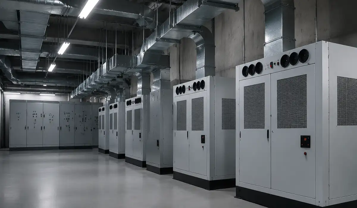
Capacitor life is dominated by operating temperature, so ventilation is not optional. Standard capacitors are rated for classes such as −25/D (maximum 55 °C), and exceeding the class temperature shortens dielectric life sharply. The panel must therefore carry ventilation openings sized for the total capacitor losses, and forced ventilation with thermostatic control where natural convection is not enough. If the enclosure cannot be ventilated adequately, specify capacitors with a higher temperature class rather than accepting the heat. Schneider Electric’s guide to designing and building LV power factor correction cubicles sets out the ventilation, clearance and maintenance rules in full.
The body of the capacitor panel is made of sheet metal with a thickness of at least 1.5 mm. The panel type (floor-standing or wall-mounted) is determined based on the installed capacitor capacity. Low-capacity capacitor panels are designed as wall-mounted, and high-capacity panels are designed as floor-standing. These panels have a door for easier access to the inside of the panel. The capacitor panel is made of two separate cells that are connected to each other. One cell is for installing the capacitor, power cable or busbar, capacitor switch or contactor, and capacitor discharge resistor, and in the other cell, the main switch, intelligent regulator, fuse, signal lamp, and power meter are installed.
The cooling temperature is measured at the hottest point of a capacitor bank. This point is located between two capacitor units. If it is a single-unit capacitor, this temperature will be at a point about 30 cm from the capacitor enclosure and at a height equal to 2.3 times the capacitor height above its base level. The capacitor bank assembly (cable connection panel, regulator, and capacitor panel) is mounted by the panel manufacturer on a chassis and transported as a single unit to the place of use.
High-capacity panels are prepared for installation on a foundation, but low-capacity panels can also be made as wall-mounted panels. The connection of the panel body and all components of the capacitor panel must be reliable. In high-capacity capacitor panels, as much as possible, a suitable interlock system should be installed between the panel door and the main switch so that without turning off the main switch, access to the inside of the capacitor cell is not possible.
Inside the panel, the capacitor steps connect to the main incoming bar. That bar carries full bank current continuously plus every inrush transient, so it is sized and jointed by the same rules as any other distribution bar — see the guidance on sizing busbars by current and temperature rise and on clearance and creepage distances inside LV assemblies.
Individual Compensation for Transformers
The values suggested by manufacturers for transformer compensation capacitors are not the same. Therefore, before installing such a compensation system, consultation or recommendations from proposers is advised. Modern transformers have core laminations that require little power to change the magnetic field. If the capacitor power is high, during transformer no-load, large overvoltages may occur.
Capacitors with internal power fuses are suitable for direct connection to the transformer terminals, only when connecting the capacitor it must be considered that the capacitor connection cable must be suitable for a short-circuit power.
Note: Capacitors with internal power fuses must not be pulled out inside the load riser, because due to pure capacitive load consumption, it causes the formation of an electric arc. If it is necessary to disconnect the capacitor from an energized transformer, a circuit breaker should be used instead of a fuse switch.
Motor Capacitor Sizing: The 90% No-Load Rule
The capacitor power should supply about 90% of the apparent power of the motor at no-load. In this way, at full load, the power factor will be 0.9, and at no-load, the power factor will be between 0.95 and 0.98.
Machines that have been individually compensated and have a capacitor connected to the motor terminals must never have their capacitor power selected too large, especially in devices that have high torque and still rotate after shutdown.
A capacitor placed in parallel with the device can excite the motor similar to a generator and thus create dangerous high voltages, which most likely damages the capacitor and motor. In the simplest form, the capacitor is connected directly to the motor terminals. In this case, capacitor protection can be omitted because the motor fuse protects the capacitor.
If a motor protection switch is installed, it is recommended that a lower trip threshold current be selected. After disconnecting voltage, the capacitors are discharged directly by the low-resistance windings. Therefore, large discharge resistors are not necessary.
Power Factor Compensation: Key Takeaways
Power factor (cos φ) is the ratio of active power to apparent power, and reactive power can increase current, losses, and costs without performing useful work. Reactive power compensation, commonly via capacitor banks, helps reduce network current, voltage drop, and losses while improving usable capacity. Proper selection of capacitors, protective devices, switching methods, and control logic (including regulators and step control) is essential for reliable operation. If you are planning correction for a facility, compile load data and design the capacitor bank based on measured or billed values to reach the target power factor.
Capacitor panels are busbar work as much as they are capacitor work. PAYAPRESS builds the CNC busbar cutting, punching and bending machines that panel builders use to fabricate the bars inside them.




Rate this article
Choose a rating from 1 to 5 stars.
No ratings yet