






Prefer listening? You can play the audio version of the rest of this article below.
What is a D-profile busbar?
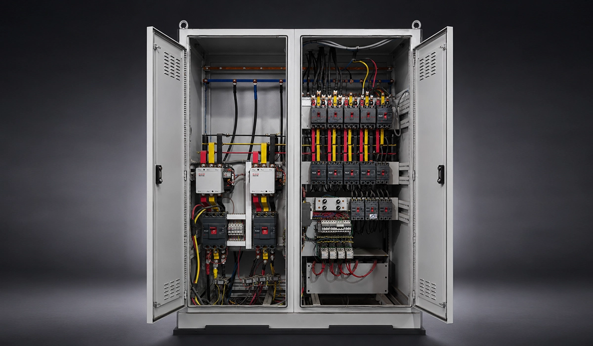
The geometry is in the name. One face is flat, and that flat face is the joint face where bolted connections are made. The other face is rounded or semi-circular. In ABB’s UniGear ZS1 the section is described as a double D-shaped cross-section on the 12 kV and 17.5 kV units. That means two D sections arranged so the flat faces provide the bolting surfaces, with the rounded backs facing outward.
The material does not change. A copper busbar in switchgear is electrolytic copper whether it is flat or shaped. What changes is the cross-sectional area and how that area is distributed around the perimeter, not the alloy.
One practical point matters for everything that follows here. The profile is produced by extrusion or by drawing at the mill. It is not made by bending a flat bar, and no panel shop creates it. ABB’s own wording is D-shape busbar, so both spellings describe the same part.
If you prefer a short introduction before the details, this overview explains the basics in a few minutes.
D-profile compared with flat, round and tubular bars
Four profiles cover almost all switchgear practice. Busbar types are chosen for joint access, cost and copper busbar current carrying capacity by shape together. A flat busbar vs D shape busbar decision is the one that comes up most often.
| Profile | Typical use | Main advantage | Main limitation |
|---|---|---|---|
| Flat bar (rectangular) | Most LV and MV panels; all branch and feeder connections | Cheapest, easiest to cut, punch and bend; stock material | Skin and edge effect waste the core at very high AC currents; stacking adds copper cost |
| D-profile / D-shape | MV switchgear main busbars at high rated current | Rounded face smooths the field, better surface-to-volume ratio, flat face still gives a clean bolted joint | Special extruded section, longer lead time, cannot be bent like flat bar |
| Round bar | High-voltage and specialised switchgear | Best corona behaviour, no sharp edges | Awkward to bolt; needs adapters at every joint |
| Tubular busbar | Very high current substation and GIS busbars | Hollow core saves copper because the core carries little AC current anyway | Bulky, needs dedicated supports and end fittings |
A flat busbar wins on every practical count until the physics overrules it. An aluminum busbar for switchgear duty follows the same logic at a larger section.
Additional details that go beyond the scope of this page are available on this site.
Busbar shape is only one piece of a larger distribution puzzle that includes ratings, spacing and enclosure design. For the full picture of how conductors, panels and protection devices work together, see this power distribution guide.
Why MV switchgear moves to a D-profile above 2,500 A
At 630 A or 1,250 A a flat copper bar behaves almost like a DC conductor. Current density is nearly uniform, the whole section does useful work, and adding copper adds capacity in a straight line.
Somewhere above 2,500 A that stops being true. Extra copper returns less and less, because the added material sits where the current is not. A switchgear busbar at that rating is limited by how current distributes itself, not by how much metal is present. Choosing a busbar shape for 4000 A switchgear is a distribution problem.
Ask why are switchgear busbars D shaped and three effects answer it: skin effect, proximity effect, and heat removal from an enclosed compartment.
One caution before the numbers. The 2,500 A figure is not a law of physics, and no standard sets it. Each manufacturer decides it, and ABB publishes theirs openly. An electrical switchgear busbar from another maker may cross over slightly differently.
To see how this works in a real situation rather than in theory, look at this case study.
Skin effect and edge effect
In alternating current, current density is higher near the conductor surface than at its core. Part of the cross-section still carries weight, cost and heat while carrying very little current.
A rectangular bar makes this worse. Its sharp corners give the current somewhere to crowd into, which is the edge effect, and the two effects together push AC resistance above DC resistance. The practical result is blunt: a solid rectangular bar rated for 4,000 A at 50 Hz does not use its full section efficiently.
A rounded face gives the current no sharp transition to concentrate at, so the distribution across the section is more even. That, in one sentence, is the whole argument for shaping the conductor at high rated currents.
If you would like to explore this subject further, you can read more about it here.
Proximity effect and phase spacing
Every busbar inside switchgear has close neighbours. Three phase bars share one compartment, so each bar’s magnetic field distorts the current distribution in the others, and current crowds toward the side facing the adjacent phase.
The consequence is local rather than general. One part of a phase runs hotter than another part of the same phase, and the hot spot sits where the field is strongest.
Proximity effect depends on frequency and spacing, not on the current value, so it does not go away by derating the panel. Shaping the conductor and setting the phase spacing correctly are the two levers a designer actually holds.
For a clearer and more complete explanation, this page goes into far more depth than we can cover in a short text.
Heat dissipation and temperature rise limits
The real constraint is not copper melting. It is the temperature-rise limit set by the type test, and IEC 62271-1 caps the permitted rise on the main circuit and on bolted joints.
Those limits are measured against a stated reference ambient. ABB rates UniGear ZS1 from −5 °C to +40 °C, at altitudes up to 1,000 m. Outside that envelope, ratings must be recalculated rather than assumed.
Copper works against you here. Its resistance rises roughly 0.4% per °C, so a hot bar is a more resistive bar, which runs hotter still. Shaping the conductor is one answer. Moving air is another: ABB reaches its 3,600 A and 4,000 A circuit-breaker ratings with forced ventilation.
None of these effects exist in isolation inside a real enclosure, where spacing, ventilation and panel layout all interact with the conductor. A closer look at how bars behave once mounted is covered in this panel busbar guide.
How ABB applies this in UniGear ZS1
ABB states in its UniGear ZS1 technical documentation that main busbars are flat bars up to 2,500 A. A special D-shape section is used from 3,150 A to 4,000 A. It is the clearest published copper busbar switchgear example available.
| Item | ABB UniGear ZS1 published figure |
|---|---|
| Main busbar material | Electrolytic copper |
| Main busbar profile up to 2,500 A | Flat bars |
| Main busbar profile 3,150 A – 4,000 A | D-shape section (described as a double D-shaped cross-section on 12/17.5 kV units) |
| Branch / tee-off conductors | Always flat cross-section, across the whole current range |
| Feeder (cable) connections | Electrolytic copper, flat busbars for the whole current range |
| Insulation of main busbars | Covered with insulating material; standard on 17.5 kV and 24 kV, available on request for 12 kV |
| Optional surface finish | Main busbar system and branches can be silver plated or tinned on request |
| Earthing busbar | Electrolytic copper, 30 × 8 mm standard, 40 × 10 mm on request, running the full length of the switchgear |
| Panel range | Up to 24 kV, 4,000 A, 50 kA |
| Main busbar rated current by voltage | Up to 4,000 A at 7.2 / 12 / 17.5 kV; up to 3,150 A at 24 kV |
| Current transformers | Block type (DIN 42600) up to 2,500 A; toroidal KOKS type from 3,150 A to 4,000 A |
| Standards | IEC 62271-1 (general), IEC 62271-200 (switchgear), IEC 62271-102 (earthing switch), IEC 60529 (IP) |
| Classification | LSC-2B, partition class PM, internal arc classified IAC AFLR |
Notice that the current transformer type changes at the same boundary as the profile. Both switch between 2,500 A and 3,150 A, which is no coincidence: the whole switchgear busbar arrangement is re-engineered above that point, not uprated. A double busbar switchgear layout is planned here too, never retrofitted.
The double D-shaped section used above 3,150 A pairs naturally with how the busbar scheme itself is arranged behind it. For a breakdown of single versus double arrangements and where each fits, see this busbar schemes comparison.
Why branch and feeder conductors stay flat
Here is the part no competing page covers. The main busbar vs branch conductor switchgear distinction rests on duty. The main bar runs the full length of the panel and carries full rated current continuously, so it suffers most from skin and proximity effects.
A tee-off does not. It is short, carries only that unit’s current, and must end in a bolted joint and pass through insulating bushings. Over that length a flat face beats an optimized section. ABB confirms it: branch conductors always have a flat cross-section, and feeders are flat busbars across the current range.
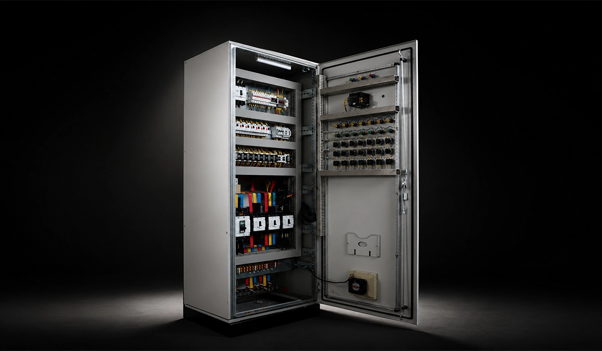
The consequence for a panel builder is easy to miss. Most of the copper in a busbar in switchgear panel assembly is still flat bar, cut, punched and bent in-house, even at 4,000 A.
Flat bar’s dominance in branch and feeder work is not unique to MV switchgear; the same logic drives most selection decisions at lower voltages too. This LV selection guide walks through those choices in more detail.
What a D-profile changes in the workshop
Start from an honest statement: a D-profile bar is a specified, purchased section. The panel builder does not create the profile. The panel builder cuts it to length, prepares the joint faces, makes the holes, and then fabricates every flat connecting part around it.
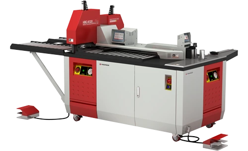
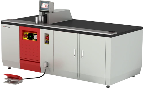
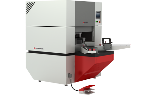
That division of labour decides which busbar processing machines a shop actually needs for high-current work. The main bar arrives shaped. Everything else is made in-house.
So the shaped section changes three operations, not the whole workshop. Cutting has to hold a bar that is not rectangular. Punching has to fixture a round back while working the flat face. Bending leaves the main bar entirely and reappears, in volume, on the flat parts around it.
Cutting and end preparation
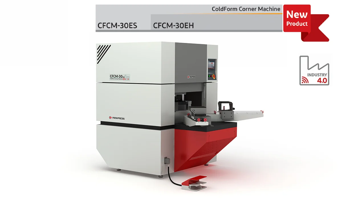
A shaped section does not sit in a standard flat-bar clamp the way a rectangular bar does. Cutting a D-profile needs correct support, and often a dedicated die or fixture.
A square, burr-free cut matters more here than on flat bar, because the joint is where a high-current system makes its extra heat. ABB lists overheating of the contact area, from corrosive agents or loose connections, among the causes of an internal arc. Deburr and clean the joint face before assembly: contact resistance at a bolted joint is where these systems fail first.
Hole punching and drilling
Holes go through the flat face, so the punching operation itself is familiar. What changes is holding a bar whose back is round, which is a fixture problem rather than a force problem.
Thicker sections do raise the force, so a punching machine has to be sized for the section, not for bar width alone. For scale, take ABB’s UniGear ZS1 tee-off connections at 3,150–4,000 A. Each joint uses four 10 × 60 mm screws, eight M10 washers, four M10 nuts and a 5 mm spacer.
The flat parts that still need bending
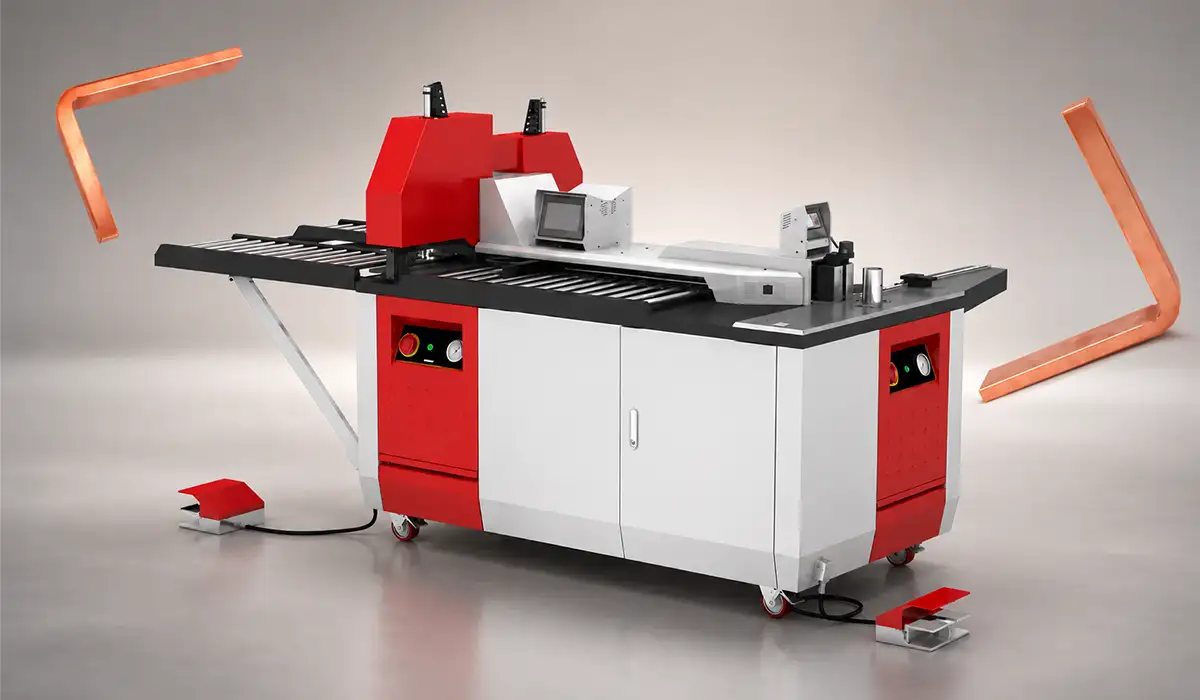
A D-profile section is not bent, so all shaping in the panel moves onto the flat parts: branch connections, feeder connections, earthing bars and cable-lug adapters.
Finish comes last. Main bars and branches can be silver plated or tinned on request, and plating quality at the joint matters more than bulk conductivity because current concentrates at the surface. Plating follows cutting, punching and bending, so fabrication tolerances have to be right first.
Since every flat connecting part around a D-profile bar still has to be bent to fit, getting the bend allowances right matters as much as the cut. This bending calculation guide covers the method panel builders use.
Specification checklist for a high-current busbar system
Work through these in order for any industrial switchgear busbar system at high rated current.
- Confirm rated current and whether it crosses the maker’s flat-to-shaped threshold.
- Confirm short-time and peak withstand current — electrodynamics forces set support spacing, not the continuous rating.
- Confirm ambient temperature and altitude against the tested reference conditions.
- Allow for thermal expansion over the full busbar run.
- Decide joint-face plating: bare, tinned or silver.
- Confirm the insulation covering required at that voltage.
- Check lead time: a shaped section is not stock material.
- Plan flat-bar fabrication separately from main bar procurement.
Ampacity comes from DIN 43671 and the manufacturer’s data, never a rule of thumb.
Short-time and peak withstand current deserve their own attention beyond this checklist, since they set support spacing rather than the continuous rating. This short-circuit withstand guide explains how those forces are calculated.
Conclusion about What Is a D-Profile Busbar
A D-profile is what medium voltage switchgear uses when a flat bar stops being an efficient conductor, in practice above about 2,500 A. Skin effect, proximity effect and heat removal all push the same way there.
The shape decision belongs to the main bar alone. Every branch, feeder and earthing conductor around it stays flat, so the fabrication work in the panel does not go away — it moves.
Shaped conductors are one step in a longer evolution of how busbar systems are designed and specified. For where that evolution is heading next, see this busbar trends overview.


Rate this article
Choose a rating from 1 to 5 stars.
No ratings yet