


If you’d rather listen than read, feel free to play the audio file below for the rest of this article.
What Are Electrodynamic Forces?
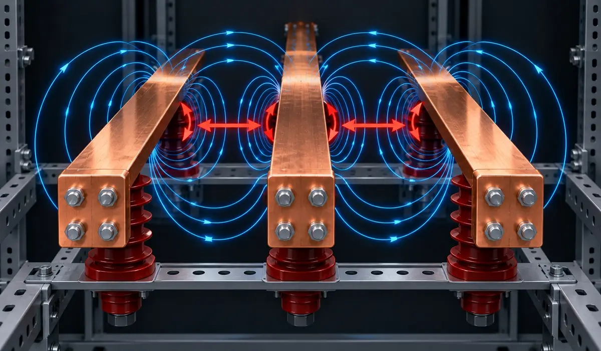
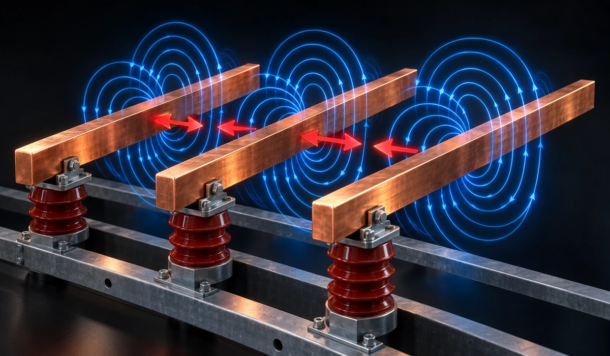
Every current-carrying conductor sits in the magnetic field of its neighbours, and that field pushes on it. Physicists call this push the Lorentz force; on busbars, engineers call it an electrodynamic force.
In other words, a short circuit force is simply the force between two parallel conductors, scaled up. In normal service, it is small. In a fault, however, current rises tens of times, and the force rises with its square: 20 times the current gives 400 times the force.
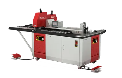
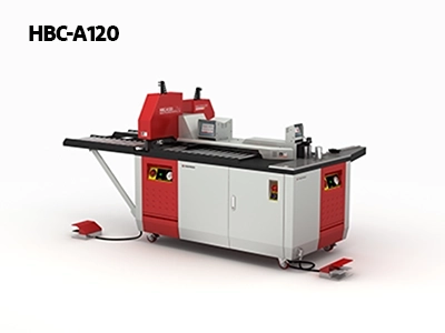
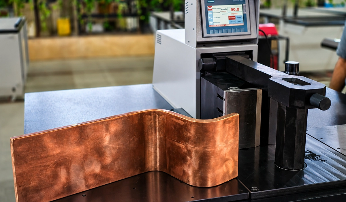
The HBC-BE120 machine is designed to produce precise bends in copper and aluminum busbars for electrical panel manufacturing. Its hydraulic bending system supports repeatable forming operations for different busbar configurations.
That is why busbars bend during short circuit events: each push lasts milliseconds but can exceed what copper and insulators carry. Conductors with opposite currents repel, while those with currents in the same direction attract. In a three-phase system, the direction changes through each cycle, so the bars shake back and forth.
These forces act on the conductors that carry power through every panel and facility. To see how bars are chosen and arranged in real installations, read our complete guide to busbar systems.
The Formula Behind the Force
The simple short circuit force calculation for two bars is F = 2 × 10^-7 × ip² × l / a, where:
- F: force on the bar, in newtons (N).
- ip: peak short-circuit current, in amperes (A).
- l: support span, the distance between supports, in metres (m).
- a: phase spacing, centre to centre, in metres (m).
However, IEC 60865 refines this. For a three-phase fault, it also adds a factor of √3/2 for the middle phase, which usually sees the highest force, plus factors for the support arrangement and conductor shape.
The rule behind this is a standard result in physics. OpenStax derives the force per unit length between two parallel currents in its parallel currents chapter.
Worked example (hypothetical example): a 25 kA RMS fault, a peak factor of 2.5, a = 0.25 m and l = 1 m.
- Peak current: ip = 2.5 × 25,000 = 62,500 A.
- Squared: ip² = 3,906,250,000 A².
- Two-conductor case: F = 2 × 10^-7 × 3,906,250,000 × 1 / 0.25 = 3,125 N.
- Middle phase: 3,125 × 0.866 ≈ 2,706 N, or about 2,700 N.
Thus the short circuit force on busbars here equals the weight of about 320 kg. Our withstand guide covers the full method.
Those correction factors come from the international standard for short-circuit effects. The IEC describes its procedures for electromagnetic effects on rigid and flexible conductors on its IEC 60865-1 page.
The fault current in this formula also drives the size of the bar you need in the first place. Learn how to pick the right cross-section in our guide to busbar sizing.

Why the Peak Current Matters, Not the RMS Value
The force follows the instantaneous current, not an average. Therefore, the first asymmetrical peak of the short circuit current, just after the fault starts, sets the maximum force.
The peak is ip = κ × √2 × Ik, where κ depends on the X/R ratio. For switchgear ratings, IEC uses a peak factor of 2.5 × Ik at 50 Hz and 2.6 × Ik at 60 Hz.
Using the RMS value is the most common error. Because force goes with current squared, peak vs RMS gives a gap of 2.5², so an RMS-based calculation understates the force about six times.
What is peak withstand current? Simply put, it is the nameplate value of the highest instantaneous current the switchgear has proved it can survive.
Fixed factors let ratings from different makers compare directly. Electrical Engineering Portal states the 2.5 and 2.6 multipliers and the standard 1 s duration in its MV application guide.
Checking peak values by hand is slow when a project has many bar layouts. Dedicated busbar design software can run these calculations faster and with fewer errors.
What the Force Does to Busbars and Supports
Bending stress in the bar. Between two supports, the bar acts like a beam under load. A longer support span means more bending stress. Copper hardness also matters, since hard bar resists permanent bending better than annealed bar.
Load on support insulators. Every busbar insulator and busbar support has a rated cantilever strength. If the force exceeds it, the insulator cracks. That is how busbar support spacing affects strength: shorter vs longer spans change both bar stress and the load per support.
Joint and bolt loads. In addition, each cycle pulls on bolted joints, which can loosen connections and raise contact resistance.
Resonance can make all three worse. If the bar’s natural frequency is near the mains frequency or twice it, the forces are amplified, which is why IEC 60865-1 includes dynamic factors.
Bar profile, fault stresses and support design are closely linked. The Copper Development Association covers short-circuit stresses and protection in its busbar design guide.
Bending stress depends on both the span and the shape of the bar itself. See how to estimate it in our guide on how to calculate busbar bending.
How Switchgear Is Designed and Tested to Survive It
Switchgear nameplates carry two short-circuit values. The rated peak withstand current proves mechanical strength, while the rated short time withstand current, with its duration (often 1 s), proves thermal strength.
Both are proved by type tests on the real assembly under IEC 62271-1 and IEC 62271-200. The peak withstand test checks that bars, supports and joints survive the first peak without damage.
As a result, busbar short circuit withstand belongs to the tested design, not to the bar alone. Changing busbar size, phase spacing or support positions in the field can void the rating. Our MV busbar compartment guide shows where these main bars sit.
The common rules for these ratings sit in the general switchgear standard rather than in each product standard. The IEC lists the scope of that standard, which covers switchgear above 1 kV, on its IEC 62271-1 page.
Mechanical and thermal ratings work together to define how much fault a bar can take. Dive deeper into short circuit withstand and mechanical strength in our dedicated article.
Conclusion
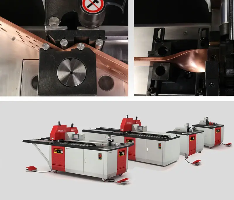
A short circuit force rises with the square of the peak current, falls as phase spacing grows and must be carried by the supports. Get the span right, and the bars will survive the fault. Support hole positions and bend geometry set that span, and PAYAPRESS machines punch and bend them exactly to drawing.
Frequently Asked Questions


Rate this article
Choose a rating from 1 to 5 stars.
No ratings yet
0 Comments
No comments yet. Be the first to comment.