






If you’d rather listen than read, feel free to play the audio file below for the rest of this article.
What Is Busbar Configuration in a Substation?
The arrangement of busbars, circuit breakers, disconnectors, feeders, and transformers determines how power moves through a substation. The busbar is the common conductor that incoming and outgoing circuits connect to; the scheme is how those connections are organised.
That organisation decides more than topology. It sets which parts can be de-energised independently, how a fault is isolated, and what must shut down for maintenance. Read on a single-line diagram, the busbar arrangement in substation drawings is usually the first thing an engineer checks, and the busbar scheme in substation design sets everything downstream of it.
Before comparing schemes, it helps to see where the busbar sits inside wider power distribution systems, because the substation arrangement sets the limits for everything downstream of it.
Why Busbar Configuration Matters in Industrial Substations
In industrial facilities, the wrong busbar configuration can increase outage risk, complicate maintenance, and limit future expansion. The cost of that mistake is rarely electrical — it is production downtime, measured in shifts lost rather than components damaged.
Four consequences recur. Fault isolation sets how much of the plant goes dark when a bus fault occurs. Maintenance access sets whether breaker servicing needs a shutdown. Expansion capability sets whether a new feeder is a bay addition or a redesign. Safety compliance depends on whether the layout permits proper clearances and isolation.
The same four consequences continue further down the system, where the different power distribution boards repeat the substation logic at panel level.
Key Design Inputs Before Selecting a Configuration
Substation busbar design criteria come down to eight inputs, and they should be fixed before any scheme is drawn.
Voltage level. An MV substation busbar system serving plant distribution has different economics from an HV installation at a utility interconnection. Complexity that is routine at 132 kV is rarely justified at 11 kV.
Load current and future capacity. Continuous rating must cover present load plus a defined expansion margin, not just today’s peak.
Short-circuit level. Busbars and switchgear must withstand the thermal and mechanical stresses of a fault. Underestimating prospective fault current is among the most expensive errors available.
Number of feeders and transformers. Bay count drives complexity, and more bays justify more robust arrangements because the consequence of a bus outage rises with circuit count.
Reliability requirement. General manufacturing tolerates interruption differently from a continuous process plant or smelter where restart runs into days.
Maintenance philosophy. The governing question is whether maintenance may occur only during planned shutdowns, or must be possible with the substation live.
Space and layout. AIS installations need considerably more area than GIS, and indoor and outdoor arrangements impose different clearances.
Budget and lifecycle cost. Cheaper schemes shift cost into downtime risk rather than removing it.
Once these inputs are fixed, the conductor itself follows from them, and correct busbar sizing turns current rating, temperature rise, and short-circuit withstand into real cross-section decisions.
Common Types of Busbar Configurations
The types of busbar arrangements in substations run from a single conductor to fully duplicated systems, with cost and reliability rising together.
If any of the terms below are unfamiliar, a short review of what a busbar is makes the comparison between these arrangements much easier to follow.
Single Busbar
The single busbar configuration is the simplest and cheapest arrangement: one bus, one breaker per circuit. Operation is straightforward and the single-line diagram easy to read. The limitation is absolute: any bus fault or bus maintenance de-energizes the entire substation. Suitable for small substations and non-critical loads only.
Even in this simple layout, every outgoing circuit still lands on a properly rated terminal bus bar, and loose or undersized terminations remain a common source of heating.
Single Busbar with Bus Sectionalizer
Adding a bus section in substation layouts splits the bus into halves joined by a sectionalising breaker. One half can be isolated for maintenance or during a fault while the other stays energized — a substantial reliability gain for modest cost, suiting medium-sized industrial substations.
For engineers and procurement teams, this downloadable file provides a useful reference for decision-making.
Main and Transfer Busbar
The main and transfer busbar arrangement adds a second bus used only while a breaker is out of service. A bus coupler in substation service transfers the feeder across so the breaker can be maintained without interrupting supply. Understanding how bus coupler works in substation busbar system terms matters before adopting this scheme, which buys maintenance flexibility at the price of more complex switching.
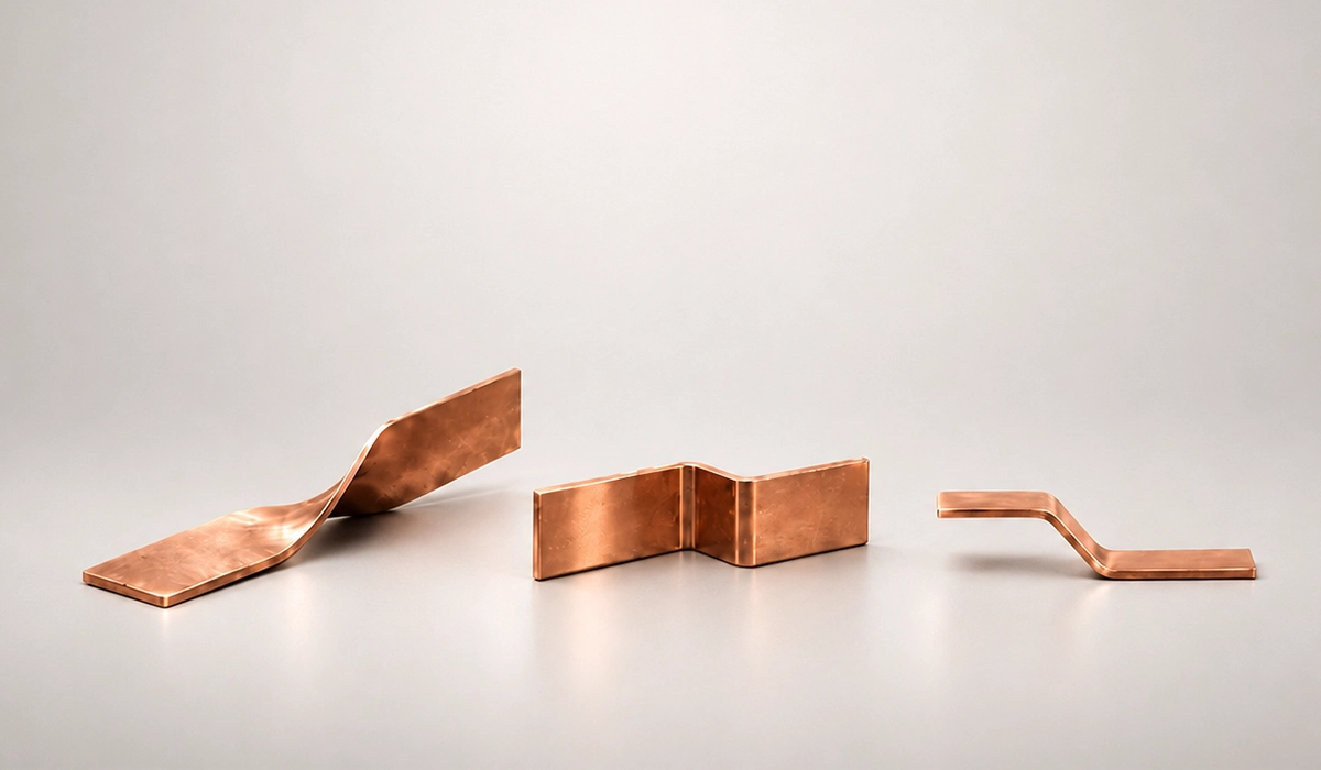
Transfer connections between bays are frequently made with a flexible busbar, which absorbs vibration and thermal movement while keeping the routing around breakers simple.
Double Busbar
The double busbar configuration provides two full buses, each feeder connecting to either through selector disconnectors. Load can be split, one bus maintained while the other carries the plant, and faults confined to part of the load. Cost and protection complexity rise accordingly.
Ring Bus
A ring busbar configuration connects breakers in a closed loop, with circuits tapped between adjacent breakers. Opening two breakers isolates any element without dropping the rest, so no transfer bus is needed. Common in HV substations. Protection design requires care, since an open ring can compromise supply.
Breaker-and-a-Half
The breaker-and-a-half bus configuration places three breakers across two buses serving two circuits, giving each circuit a dedicated breaker plus a shared centre breaker. Any breaker or bus can be removed from service without interrupting either circuit. Expensive and space-hungry, and standard practice for critical HV substations.
Double Bus Double Breaker
Every circuit gets two breakers, one to each bus. Reliability is the highest available, and any single element can be maintained or fail without affecting supply. Cost is correspondingly highest, restricting it to mission-critical systems where downtime is unacceptable.
Busbar Configuration Comparison Table
The table summarizes the trade-offs. Treat it as a shortlisting aid rather than a selection decision.
| Configuration | Reliability | Cost | Maintenance Flexibility | Best Use Case |
|---|---|---|---|---|
| Single Busbar | Low | Low | Low | Small Substations, Non-Critical Loads |
| Single Busbar with Sectionalizer | Medium | Low–Medium | Medium | Medium Industrial Loads |
| Main and Transfer Bus | Medium | Medium | Medium–High | Facilities Needing Breaker Maintenance Flexibility |
| Double Busbar | High | High | High | Large Industrial Substations |
| Ring Bus | High | Medium–High | High | HV Substations |
| Breaker-and-a-Half | Very High | High | Very High | Critical HV Substations |
| Double Bus Double Breaker | Maximum | Very High | Maximum | Mission-Critical Power Systems |
How to Select the Right Configuration
Work through seven steps in order. First, define the substation function: factory distribution, utility interconnection, renewable plant, data centre, or mining site each carry different expectations. Second, classify load criticality as non-critical, important, critical, or mission-critical. Third, identify required redundancy — N, N+1, or fully duplicated supply. Fourth, analyse fault levels and confirm protection coordination is achievable within the scheme. Fifth, establish outage tolerance: can the facility accept a complete shutdown for busbar or breaker maintenance? If not, the simpler schemes are eliminated immediately. Sixth, plan expansion with spare bays for future transformers and feeders. Seventh, balance cost against downtime risk in production terms, not capital terms alone.
The same seven steps apply to renewable and battery-backed sites at low voltage, where a Victron busbar is a familiar solution for DC collection and distribution.
Busbar Protection and Safety Considerations
Protection design and bus arrangement are decided together, not sequentially. Bus differential protection gives fast, selective clearance of bus faults, and its zones must align with the sections the scheme creates. Breaker failure protection matters more as arrangements grow complex, since a stuck breaker in a ring or breaker-and-a-half layout has wider consequences.
Interlocking prevents disconnectors being operated under load during transfers, and earthing, clearances, and arc flash assessment follow from the physical layout. Busbar protection requirements in substations should be confirmed alongside the scheme, not retrofitted to it.
Earthing quality belongs to the same design stage, and a correctly sized ground bus bar gives fault current a low-impedance return path so protection operates as intended.
Safety note: Final substation busbar design should always be verified by qualified electrical engineers according to applicable local codes, utility requirements, and project specifications.
Example Configuration Choices for Industrial Projects
Four cases illustrate the pattern. A small industrial facility with non-critical load is served by a single bus, or a sectionalised one where modest redundancy is wanted. A large manufacturing plant with many feeders justifies a double busbar or main and transfer arrangement. A critical process plant intolerant of unplanned interruption points toward a ring bus or breaker-and-a-half. A utility or HV interconnection typically requires breaker-and-a-half or double bus double breaker, reflecting the HV substation bus arrangement conventions utilities apply.
Common Mistakes in Configuration Design
Recurring errors are predictable. Selecting the cheapest scheme without reliability analysis. Ignoring expansion, then finding no bay space remains. Underestimating short-circuit current, which invalidates equipment ratings. Treating protection as a later exercise rather than a parallel one. Inadequate maintenance access. Failing to price downtime when comparing options. And applying MV assumptions to an HV substation, where conventions differ. Sound industrial substation busbar design considerations address all seven before a scheme is fixed.
One further input is often overlooked at this stage: a poor power factor raises current for the same real load, so conductors and switchgear end up working closer to their limits than the design assumed.
Conclusion about Busbar design
The correct arrangement follows from technical, operational, and commercial inputs considered together. Reliability requirement and maintenance philosophy usually narrow the field faster than any other factor, with cost setting the final choice among the remaining candidates.
Need support selecting the right arrangement for an industrial substation? Contact our engineering team for substation design, switchgear selection, and power distribution system support.



Rate this article
Choose a rating from 1 to 5 stars.
No ratings yet