



What Is a Battery Busbar?
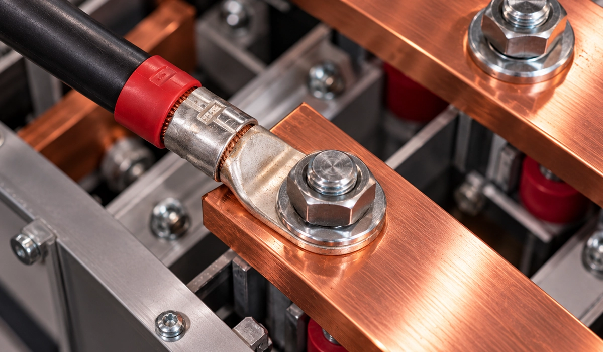
A battery busbar is a rigid conductor, usually copper, that joins battery terminals or cells and collects their current into one point. From there, loads, chargers and inverters draw power through short, separate connections.
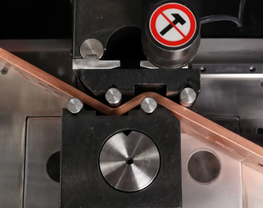
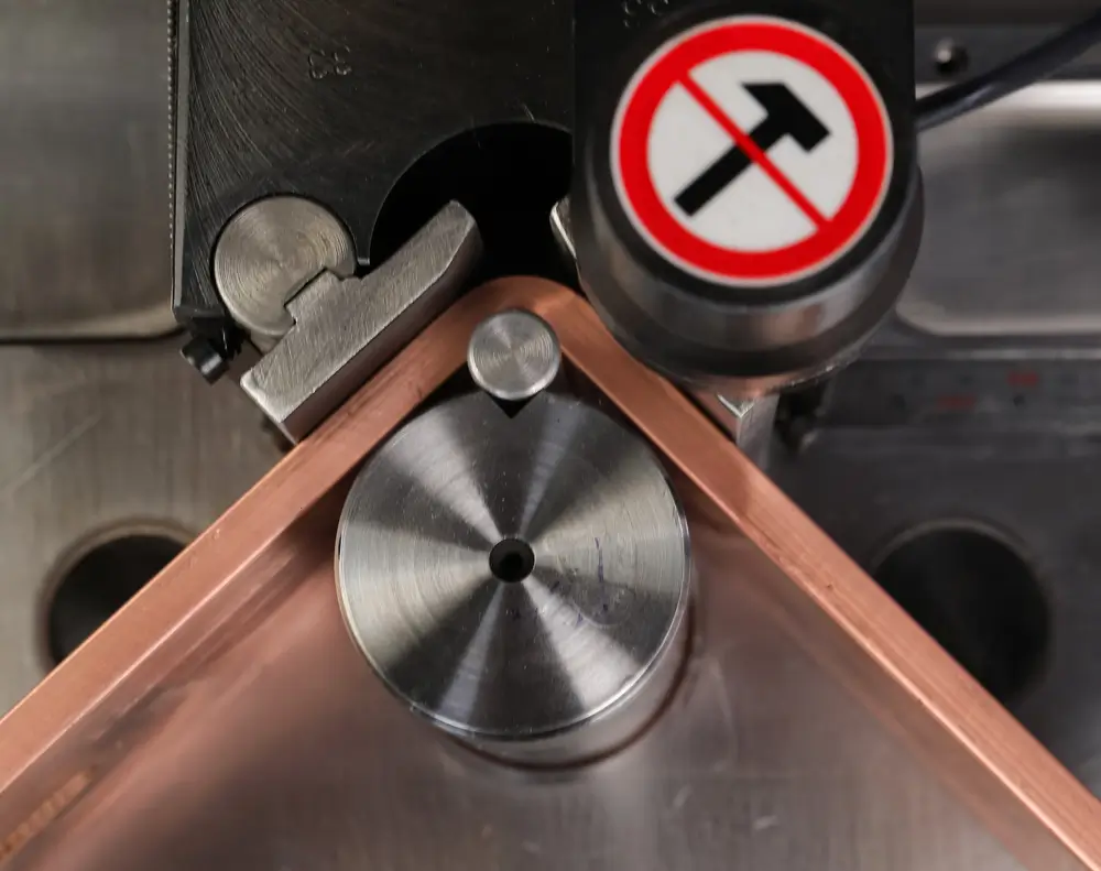
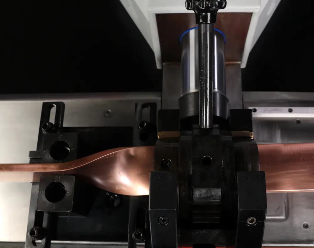
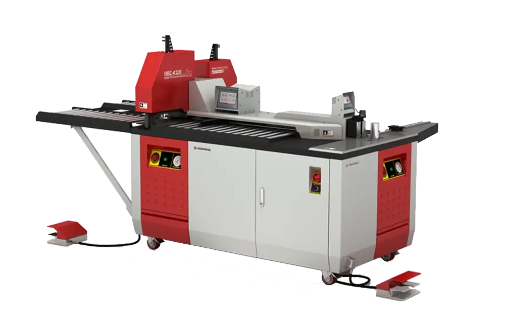
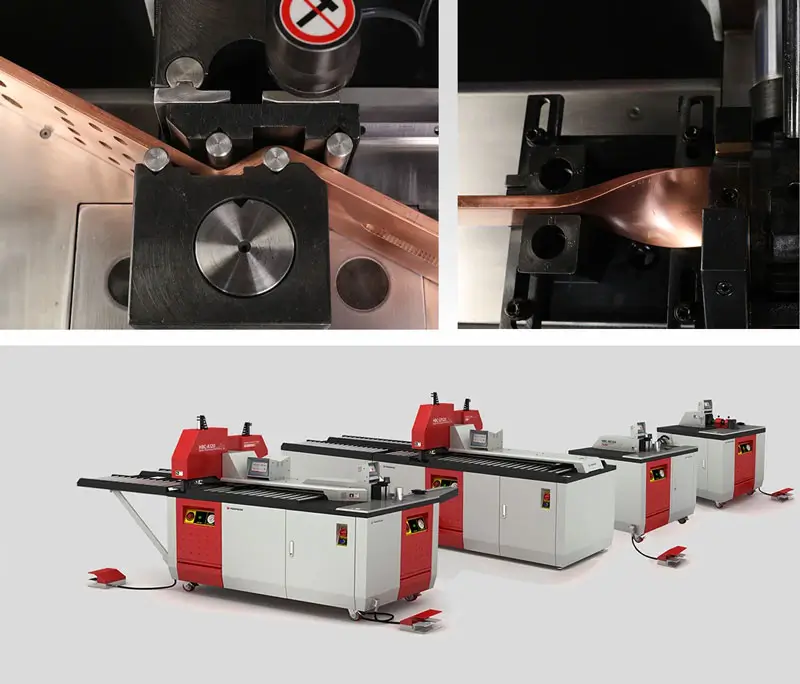
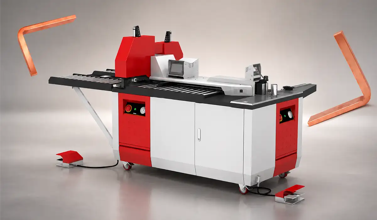
For larger or thicker bars, a HBC-PC120 machine gives clean, repeatable bends without stressing the copper.
In practice, a busbar for battery systems does three jobs:
- Combines parallel batteries, so each battery sees equal cable length and shares current evenly.
- Gives every load and charger its own stud, which keeps circuits tidy and easy to trace.
- Keeps cable lugs off the battery posts, so the terminals carry one clean connection each.
For example, a parallel battery bus bar on a four-battery bank feeds every battery through equal cables. As a result, battery bus bars make later expansion simple.
Bus Bar vs Terminal Block vs Stacked Lugs
What’s the difference between a terminal block and a bus bar? A terminal block keeps separate, isolated circuits apart, whereas a bus bar is one common conductor that every connection shares. However, many DIY banks skip both and stack four or five lugs on a single battery post. That stack is a common cause of loose, hot connections, because each lug adds a contact surface. A battery terminal bus bar solves the problem: it bolts directly to the post with one lug and offers several studs for loads. Similarly, a battery busbar connector or power post moves extra cables off the terminal, so the post carries a single, tight joint.
Two Kinds of Battery Busbars: House Banks and Battery Packs
Two very different products share the same name.
| Type | Where | Typical joint | Typical current |
|---|---|---|---|
| House-bank bus bar | 12 V, 24 V and 48 V solar, marine and RV systems | Stud bars with bolted cable lugs | Tens to a few hundred amps |
| Pack busbar | Inside EV and BESS modules, joining cells | Thin plated copper or aluminum, often laser-welded | Hundreds of amps in short runs |
An ev battery busbar sits inside a cooled, sealed module, while a 12v battery bus bar in an RV sits in open air. Where cells swell or move, designers use a flexible busbar or a laminated busbar. Therefore, the sections below flag which advice applies to which type.
How to Size a Battery Bus Bar
What size bus bar do I need for my battery bank? You size a battery bus bar three times: first for continuous current, then for voltage drop and heat, and finally for the short-circuit current the bank can deliver. The largest answer wins. The three steps below show how to size a bus bar for a battery bank, and the worked example applies them to a 48 V bank.
Assembly standards cap how hot conductors may run, so every bar size must respect a verified temperature-rise limit. The IEC catalogue entry describes the scope and temperature-rise verification rules in its IEC summary.
Step 1: Continuous Current and Current Density
Start with the formula: area (mm²) = design current ÷ current density. Design current is the highest continuous load, usually the inverter input at low-battery voltage, multiplied by a 1.25 margin (hypothetical estimate; confirm it against your governing code). The result gives the minimum cross-sectional area of the bar.
Battery bus bar current density varies widely by application. For example, LV switchgear and enclosed house banks typically use about 1.0 to 1.6 A/mm² for copper. In contrast, published pack-design data suggests about 5 A/mm² as a first estimate for EV pack busbars. That gap exists because pack bars are short, actively cooled and allowed to run hotter. Therefore, never copy a pack figure into a house bank. A bigger bar costs more copper, but it also runs cooler and wastes less energy over the bank’s life, so many designers round up to the next standard size. For the full method, see our guide to busbar sizing, and check standard bar ratings in copper busbar current ratings.
Step 2: Voltage Drop and Temperature Rise
Next, check losses with three formulas: R = ρ × L ÷ A, voltage drop = I × R, and heat = I² × R. Here ρ is resistivity, L is length and A is the cross-section; see resistivity of copper for the values. At 12 V, every millivolt counts more than at 48 V, because the same drop is a larger share of the system voltage. Similarly, a 12 V bank carries four times the current of a 48 V bank for the same power. As a result, low-voltage banks often need a larger bar than current density alone suggests. Finally, temperature rise limits in IEC 61439-1 for assemblies cap the design, so the bar must stay within the allowed rise at full load.
Step 3: Short-Circuit Current
Then size the bar for the worst case of all. Lithium banks can deliver short-circuit current many times their rated load, because their internal resistance is very low.
During a fault, the bus bar, its studs and its supports must carry that current until the fuse opens. Moreover, they must do so without bending, loosening or overheating, since magnetic forces between parallel bars rise sharply with fault current. Take the prospective short-circuit current from the battery datasheet; no generic number is safe, because cell chemistry, bank size, temperature, state of charge and cable length all change it. Consequently, the fuse, the bar and the hardware must all be rated for that figure. The fusing section below explains interrupt rating and why a Class T fuse is common on lithium banks.
Worked Example: 48 V Bank With a 5 kW Inverter
This is an example, so verify every figure for your system. A 5,000 W inverter at a 44 V low cutoff and 90% efficiency draws 5,000 ÷ (44 × 0.90) ≈ 126 A. With the 1.25 margin, the design current becomes about 158 A. At 1.5 A/mm², the bar needs about 105 mm², so a 30 × 4 mm battery bus bar copper section (120 mm²) fits.
Now check the losses. A 300 mm length of that bar has about 43 µΩ of resistance at 20 °C. At 158 A, that gives roughly 6.8 mV of drop and about 1.1 W of heat. Both values are small for a 48v battery bus bar. Finally, check the short-circuit case before you order material. To repeat the math for other sizes, use our copper busbar calculator.
Material: Copper or Aluminum?
Copper (C11000, at least 100% IACS) is the default for house banks. It needs the smallest section and makes easy bolted joints. However, aluminum is about 61% IACS, so it needs roughly 1.6 times the copper cross-section for the same current. In return, it saves weight in large EV modules and grid storage, where cell terminals are often aluminum.
| Property | Copper (C11000) | Aluminum (EC grade) |
|---|---|---|
| Conductivity | ≥100% IACS | About 61% IACS |
| Section for same current | 1× | About 1.6× |
| Density | 8.9 g/cm³ | 2.7 g/cm³ |
| Joint care | Simple bolted joints | Oxide removal, compound, plating |
| Typical use | House banks, panels | EV modules, grid storage |
The aluminum vs copper battery busbar choice turns on weight, terminal metal and joint care. See our copper busbar guide and the benefits of aluminum busbar article.
Conductor grades set the real conductivity gap, so sizing should start from published minimum values. The reference table lists minimum IACS values for 1350 aluminum in its aluminum conductor data.
Plating: Bare, Tin or Nickel
Bare copper tarnishes over time, and contact resistance rises as the oxide layer grows.
| Finish | Benefit | Watch-out |
|---|---|---|
| Bare copper | Lowest cost, best conductivity | Tarnishes; clean before assembly |
| Tin plating | Stable bolted contacts; helps where copper meets aluminum | Softer layer; avoid high-heat welding |
| Nickel plating | Resists heat and corrosion; welds well | Slightly higher contact resistance |
A nickel plated copper battery busbar is therefore common on lithium pack and rack busbars. Note that cut and punched edges on plated bars expose bare copper. In dry enclosures this rarely matters, since current flows through the plated face. In marine or damp sites, however, plate after punching.
Tin layers resist oxidation better than raw copper, so bolted contact faces stay conductive longer. The finishing company describes tin’s oxide behavior and underplate choices in its tin plating guide.
The Weak Point: The Joint, Not the Bar
A correctly sized bar runs cool along its length. Heat instead concentrates where current crosses from one surface to another, because every contact adds resistance. Therefore, joints fail in three main ways: bolted joints relax, welded joints degrade, and mixed-metal joints corrode. Each failure raises resistance, adds heat and speeds the next stage of damage.
Laboratory data now shows how quickly joint resistance climbs once heat and movement act together on a pack connection. The Warwick research team measured welded aluminum joints under current and mechanical load in its busbar joint study.
Bolted Joints: Relaxation, Torque and Overlap
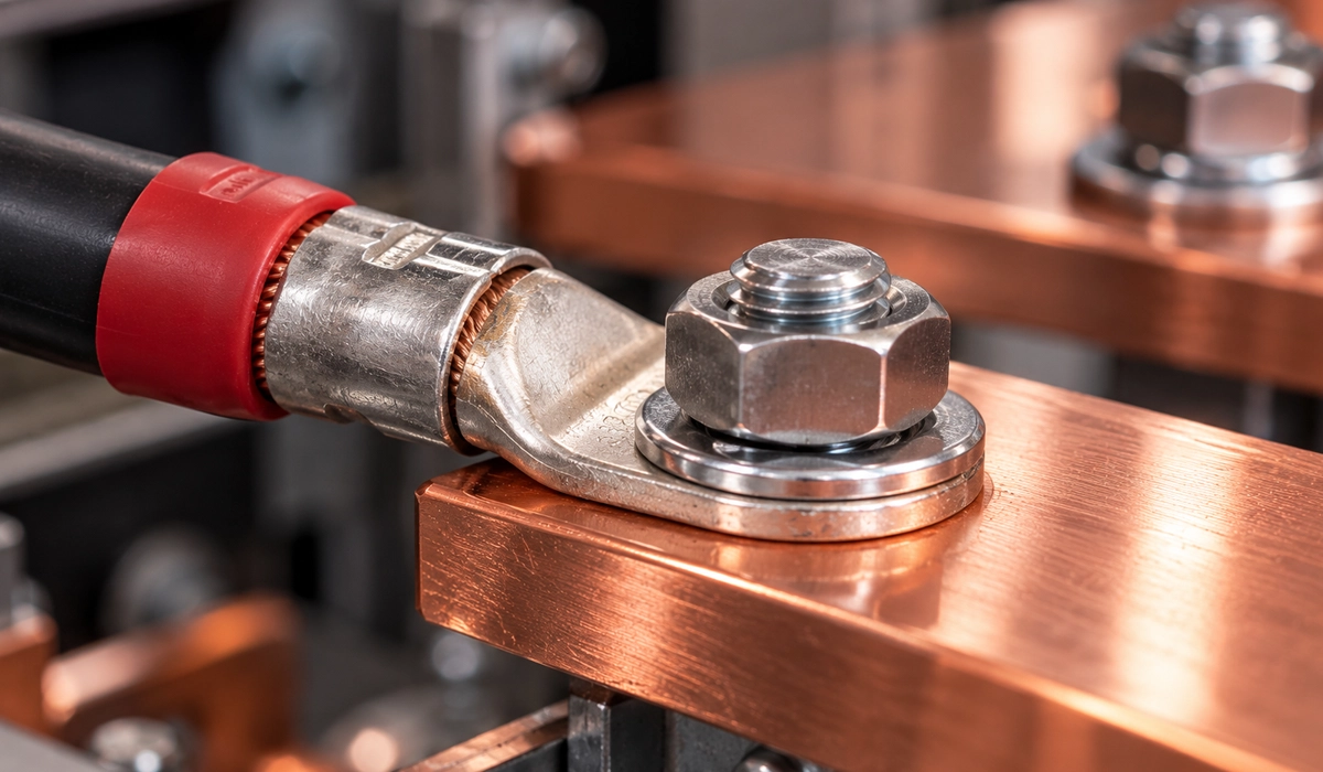
Joint relaxation happens when clamp force drops over repeated thermal cycling. Then resistance rises, the joint heats, and the cycle accelerates. To prevent it, use an overlap of 5 to 10 times bar thickness for bar-to-bar joints, as published pack-design guidance suggests. In addition, keep contact faces flat and burr-free, and use spring washers to hold clamp force. For battery bus bar torque, follow the battery or terminal maker’s value, since no universal number exists. Finally, re-check torque after the first thermal cycles, and see cable lugs and busbar for lug choice and crimping.
How do you connect a busbar to a battery? Follow these steps:
- Fit a fuse close to the battery positive terminal.
- Clean the post, the lug and the bar face.
- Crimp the cable lug and bolt it flat to the post and the bar.
- Torque every nut to the specified value, then re-check later.
Welded Joints in Battery Packs
In EV and BESS modules, laser welding, ultrasonic welding and resistance welding replace bolts. Battery busbar welding saves parts and assembly time. However, the battery busbar laser welding vs bolted choice has a trade-off: a weld is weaker than a bolted joint under vibration and impact.
For example, a 2024 University of Warwick study (Kumar et al., Journal of Energy Storage) loaded laser-welded aluminum busbar joints electrically and mechanically together. Lap-shear joints showed resistance rises of about 51% at 100 A and about 71% at 200 A by the end of testing. Torsion joints rose by about 28% to 60% over the same current range. Consequently, designers add flexible busbar sections that absorb cell movement and protect the welds from fatigue.
Galvanic Corrosion at Mixed-Metal Terminals
Lithium cells often have an aluminum positive terminal and a copper negative terminal. When a bare copper bar sits on aluminum and moisture reaches the joint, galvanic corrosion attacks the aluminum. As a result, resistance climbs and the joint heats. The risk is highest in marine and outdoor solar banks, where humid or salty air condenses inside enclosures. Fortunately, three fixes work well. First, use tin or nickel plating on the copper bar. Second, fit bimetallic transition pieces between the two metals. Third, apply anti-oxidant compound on bolted aluminum contacts to keep moisture and air out. In addition, inspect these joints during routine maintenance, because corrosion often hides under the lug.
Fusing and Protecting a Battery Bus Bar
Do you need a fuse between the battery and the bus bar? Yes. The conductor from the battery to the bar needs overcurrent protection close to the battery. For example, on a marine battery bus bar, ABYC E-11 requires protection within 7 inches (178 mm) of the source, measured along the conductor.
Lithium banks often use a high-interrupt-rating fuse between the bank and the bar, and a Class T fuse is the common choice. Each branch circuit then gets its own fuse on the bar. For stationary systems, check NEC Articles 706 and 480.
Can you charge a battery through a bus bar? Yes. Chargers and controllers land on a solar battery bus bar beside the loads, and each one has its own fuse.
Marine electrical specialists explain the fuse placement and interrupt ratings that lithium banks need. The author covers the 7-inch rule, its exceptions and Class T selection in his battery bank fusing.
Fabricating Battery Busbars: Cutting, Punching and Bending
Good battery busbars start with square cuts and hole positions that match cell or stud pitch. Burr-free holes keep the contact face flat, so the joint clamps evenly, while offsets and bends take up cell spacing without stressing terminals.
What we check on a busbar drawing before punching:
- Hole pitch against the layout
- Contact-face flatness
- Burr side, facing away from the joint
- Plating before or after punching
As for how to wire a 12v bus bar: use positive and negative bars, one fused feed and a fused branch per load.

Conclusion about Battery Bus Bar
A reliable battery bus bar comes down to three habits. First, size it for continuous current, voltage drop and short-circuit current. Next, pick copper unless weight decides the choice. Finally, treat every joint as the weak point, because a sound battery busbar still fails at a loose, corroded or poorly welded connection. In practice, a quick thermal scan after the first weeks of service catches most joint problems early.


Rate this article
Choose a rating from 1 to 5 stars.
No ratings yet