


If you’d rather listen than read, feel free to play the audio file below for the rest of this article.
What Is a Busbar Trunking System? Definition and Working Principle
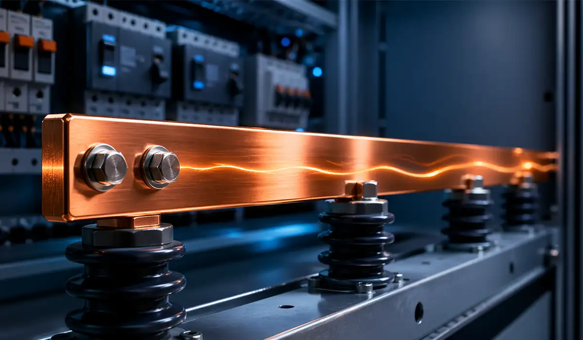
A busbar trunking system is a prefabricated power distribution assembly used to transport and distribute electrical energy through a tested enclosure-and-conductor arrangement. In IEC practice, it sits within the IEC 61439 family, with particular requirements for low-voltage BTS.
Power enters through an end-feed unit, travels along straight lengths, and can be transferred or distributed through joints, elbows, and tap-off points. That makes a power busway system modular rather than field-built.
Because the enclosure, joints, insulation system, and connection interfaces are factory engineered, electrical performance is more repeatable than with many site-assembled cable bundles. Verification also covers temperature-rise and dielectric-related performance.
In practical terms, a Busbar Trunking Systems Overview starts with one core idea: BTS moves bulk power along a tested path and makes branch distribution available where the installation needs it.
For a more detailed breakdown, download the complete guide here.
Busbar trunking systems are one part of the broader family of electrical busbars used in power distribution. Understanding how trunking fits alongside other busbar types and applications gives a clearer picture of where each solution is best applied. For a comprehensive overview, this article on electrical busbars is highly recommended as a starting point.
How Busbar Trunking Differs from Cable-Based Distribution
For engineers comparing busbar trunking vs cable, the main trade-off is flexibility against first cost. Busbar trunking installs faster, packs more current into less space, and makes relocation easier, while cable can remain economical for short, simple, low-change routes. Type-tested fault withstand and cleaner modification paths usually favor BTS in dense industrial or commercial projects.
For engineers and procurement teams, this downloadable file provides a useful reference for decision-making.
Comparing busbar trunking with cable-based distribution naturally raises questions about distribution board configurations as well, since both feed into the same downstream panels. Understanding the different types of distribution boards helps clarify how trunking and cable routes ultimately connect to the load side. This article on distribution board types provides useful context.
Types of Busbar Trunking Systems
Busbar trunking system types are usually separated by construction, conductor material, and duty class. The most important split is sandwich busbar trunking versus air-insulated construction.
A second split is functional: feeder runs move power point-to-point, while plug-in runs add branch connection capability. Rising mains are the vertical version used in multistory shafts.
Conductor choice also matters. Copper busbar trunking is more compact; aluminum busbar trunking is lighter and often less expensive for long runs.
Understanding these categories is the starting point for how to select busbar trunking for industrial applications without oversizing, under-protecting, or choosing the wrong enclosure class.
Download this file to keep the key data, tables, and recommendations in one place.
| Type | Core construction | Typical use |
|---|---|---|
| Sandwich (compact) | Laminated insulated conductors in a compact stack | Main feeders, plants, data centers, high-rise buildings |
| Air-insulated | Conductors separated by air gaps in the enclosure | Lower-density routes where footprint is less critical |
| Plug-in / rising main | Tap-off interfaces along the run | Floor-by-floor distribution and flexible branch loading |
| Feeder | No intermediate tap-offs | Transformer-to-board and board-to-board transfer |
These categories mirror current IEC-aligned product families from Siemens, Eaton, Legrand, and ABB.
The different busbar trunking types correspond closely to the broader range of busbar arrangements used throughout LV and MV systems. Reviewing a structured comparison of these arrangements can help engineers decide which trunking configuration best fits a given layout. This guide on busbar arrangements is a useful reference.
Sandwich (Compact) Busbar Trunking
Sandwich busbar trunking laminates insulated conductors into a compact stack, which reduces reactance and supports high current density. Siemens positions its LI system for 800 A to 6300 A in multistory buildings and industry, making sandwich busbar trunking vs open busbar trunking a decision about footprint, impedance, and fault duty rather than appearance alone.
Sandwich busbar trunking achieves its compact footprint partly through precise busbar sizing during fabrication. Getting the cross-section right at this stage directly affects both impedance and thermal performance once installed. This article on busbar sizing covers the key calculation principles.
Air-Insulated Busbar Trunking
Air-insulated busbar trunking keeps conductors separated by air within the housing. It can be economical in lower-density installations, but it usually needs a larger footprint and may offer lower short-circuit performance than compact sandwich designs.
For practical use, we recommend saving this downloadable reference file.
Air-insulated busbar trunking depends heavily on adequate clearances between conductors to maintain dielectric performance. Understanding the clearance requirements that apply to busbar systems helps ensure air-insulated runs meet their rated withstand levels. This article on busbar clearances explains these requirements in detail.
Plug-In (Rising Main) Busbar Trunking
Plug-in, or rising main, busbar trunking places tap-off interfaces along the run so each floor or load zone can be supplied without re-pulling feeders. That makes it a dominant approach for busbar trunking for high-rise residential buildings, hotels, and commercial towers.
Download the technical document to review the complete specifications and details.
Plug-in busbar trunking systems often rely on terminal bus bar connections at each tap-off point to distribute power to local boards. Understanding how these terminal connections are designed and rated is important for ensuring reliable branch circuits. This article on terminal bus bar provides useful technical detail.
Feeder Busbar Trunking
Feeder busbar trunking is a point-to-point assembly between sources and downstream boards. Because there are no intermediate tap-off positions, the design emphasizes low impedance, mechanical simplicity, and high fault withstand.
Feeder busbar trunking must be designed to withstand short-circuit forces along its full length, since there are no tap-offs to interrupt the fault path. Understanding short-circuit withstand and mechanical strength requirements is therefore especially important for feeder runs. This article on short-circuit withstand covers these requirements in depth.
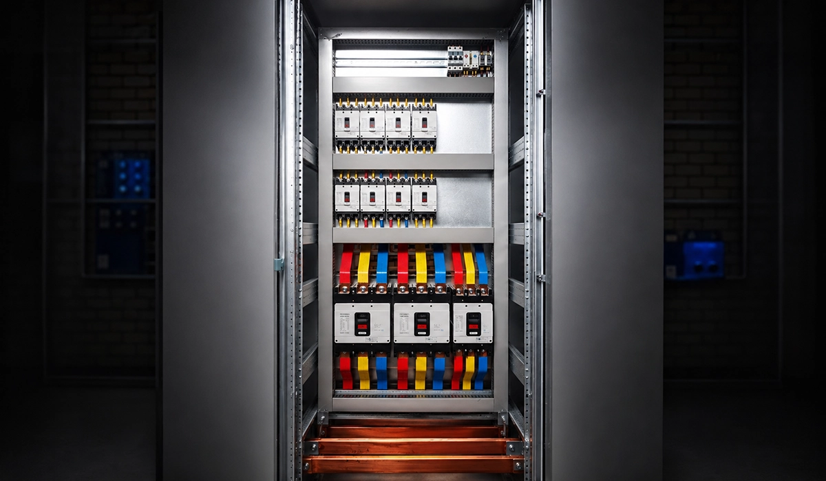
Key Components of a Busbar Trunking System
A complete BTS includes much more than straight lengths. Reliable performance depends on coordinated fittings, joint technology, supports, and accessories that keep the electrical and mechanical path continuous.
The straight unit carries bulk current, but end feeds, elbows, tees, and expansion joints determine whether the route can actually be installed within the building geometry. Fire barriers and end caps protect safety and enclosure continuity.
Tap-off units deserve special attention because protection, metering, isolation, and maintenance access are decided there. In many projects, plug-in tap-off units for busbar trunking explained properly will prevent underspecified branch distribution.
Procurement teams should therefore compare complete assemblies, not just conductor rating. A cheaper trunking run can become expensive if fittings, support hardware, or tested fire-stop accessories are missing.
We have prepared a downloadable checklist to help you apply these points in practice.
| Component | Function | Key Specification |
|---|---|---|
| Straight Length Unit | Main conductor run | Current rating, length, conductor material |
| Tap-Off / Plug-In Unit | Branch connection point for load circuits | Rated current, breaker or fuse type |
| Elbow / Bend Unit | Changes direction | 90° or 45°, matching current rating |
| T-Junction Unit | Splits run into two directions | Current rating, phase arrangement |
| End Feed Unit | Connects incoming supply | Cable entry size, incoming current rating |
| Expansion Joint | Compensates for thermal expansion | Expansion range, current continuity |
| Fire Barrier | Maintains compartment integrity | Fire rating, tested configuration |
| End Cap | Seals the terminal end | IP continuity |
| Support Hanger | Mechanical fixing to structure | Span interval per manufacturer |
The table reflects the accessory families commonly published by major busbar manufacturers and installation guides.
Among the key components of a busbar trunking system, the ground bus bar plays a critical role in maintaining a continuous earthing path along the entire run. Proper grounding at every joint and tap-off is essential for both safety and fault clearance. This article on ground bus bar explains its function and design requirements.
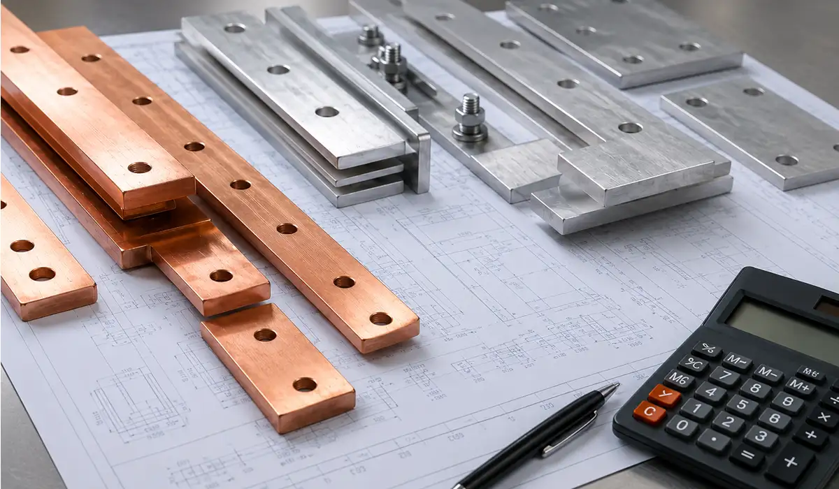
Conductor Materials — Copper vs Aluminum in Busbar Trunking
A copper vs aluminum busbar trunking comparison usually comes down to conductivity, size, weight, and cost. Copper gives higher conductivity and smaller cross-sections; aluminum reduces mass and material cost, but joints need correct surface treatment, connector design, and anti-oxidation practice to maintain long-term contact quality.
Conductor material choice in busbar trunking is closely related to flexible busbar applications, where weight and bending characteristics often determine the best material. Reviewing the available flexible busbar types and their sizing standards can help when trunking connects to flexible sections. This article on flexible busbar types provides a useful comparison.
Busbar Trunking System Standards and Ratings
The governing IEC product standard for low-voltage busbar trunking is IEC 61439-6, which replaced IEC 60439-2. It defines service conditions, construction rules, technical characteristics, and verification requirements for BTS.
That means busbar trunking current rating is only one part of compliance. Designers also have to check temperature rise, dielectric withstand, short-time withstand current, and protection against solid objects and water.
For projects outside IEC markets, North American specifications often reference UL 857 and related busway practice. IEC vs UL is therefore a market and compliance question, not simply a naming difference.
In a rigorous Busbar Trunking Systems Overview, engineers should confirm that ratings apply to the full assembly and fittings, not only to the straight section. That distinction matters during tender comparison and fault studies.
You can visit the official website for more detailed and updated information.
Busbar trunking standards and ratings sit within the broader framework of busbar standards that apply across LV and MV equipment. Familiarity with this wider standards landscape helps engineers interpret trunking ratings correctly during tender evaluation. This article on busbar standards provides a comprehensive overview.
Current Rating, Voltage Rating, and Short-Circuit Withstand
Rated current describes the continuous current capacity under stated conditions, while rated voltage defines the system limit. For low voltage busbar trunking, IEC 61439-6 covers assemblies up to 1000 V AC or 1500 V DC, and short-time withstand current (Icw) expresses the fault current the assembly can carry for a defined duration without unacceptable damage.
Current and voltage ratings for busbar trunking are easier to interpret once the fundamentals of what a busbar actually is and how it functions are clear. For readers who want to revisit these basics before working through rating tables, this introductory article on what is busbar provides a strong foundation.
IP Rating and Environmental Suitability
Busbar trunking enclosure rating should match the site, not the sales brochure. Dry indoor routes may only need modest protection, while wet or washdown zones need higher busbar trunking IP rating selections and accessories that preserve sealing across joints, tap-offs, and end fittings.
| Environment | Minimum IP Rating | Typical Application |
|---|---|---|
| Dry indoor | IP31 | Offices, commercial spaces, shopping areas |
| Industrial indoor | IP54 | Manufacturing plants, warehouses |
| Outdoor or washdown | IP65 | External risers, food processing |
| Wet / hose-down areas | IP66 | Breweries, chemical processing |
This is a practical selection table built from IEC IP-code principles and current busbar product offerings for harsher environments.
Selecting the correct IP rating for busbar trunking also depends on how the system will be installed within electrical panels and enclosures. The way busbars are integrated into panel design affects how easily the required IP continuity can be maintained at entry and exit points. This article on busbar in panels is a useful reference.
Busbar Trunking System Design and Sizing Principles
Busbar trunking system design starts with load current, diversity, route length, supply fault level, and ambient conditions. The goal is not only ampacity, but also acceptable voltage drops, thermal behavior, and mechanical fit.
This Busbar Trunking Systems Overview is most useful at this step, because sizing errors usually come from treating BTS like loose cable rather than a tested assembly with published electrical data and mounting rules.
Good design also checks future change. If machines, PDUs, or floor boards may move later, spare tap-off capacity can be worth more than a lower initial material price.
In short, how to calculate busbar trunking size for a building means combining current demand, short-circuit duty, voltage-drop limits, route geometry, and environmental derating before locking in the catalog code.
You can access the full PDF version of this reference from the link here.
Busbar trunking design and sizing principles benefit from dedicated design software that automates current density, voltage-drop, and derating calculations. Using the right software tools can significantly reduce sizing errors on complex projects. This article on busbar design software provides a practical overview.
Voltage Drop Calculation in Busbar Trunking
Manufacturers publish resistance, reactance, or direct voltage-drop data per unit length, allowing designers to calculate performance on long runs. Low-reactance sandwich systems are especially helpful where busbar trunking system for data center power distribution or long feeder corridors makes voltage drop a limiting factor.
Voltage drop calculations in busbar trunking are closely tied to single busbar versus double busbar scheme decisions at the source, since the scheme affects how load is distributed across feeders. A technical comparison of these schemes is available in this article on busbar schemes.
Thermal Rating and Derating Factors
Thermal rating depends on ambient temperature, mounting orientation, and grouping. ABB and other manufacturers publish derating data for conditions above the reference ambient, so generic cable derating rules should not be copied directly into busbar trunking system design.
Thermal rating and derating factors are also influenced by how the busbar trunking is mounted within LV panels and switchgear enclosures. Understanding how busbars behave inside LV panels helps when applying manufacturer derating tables to enclosed installations. This article on LV panel busbars provides relevant context.
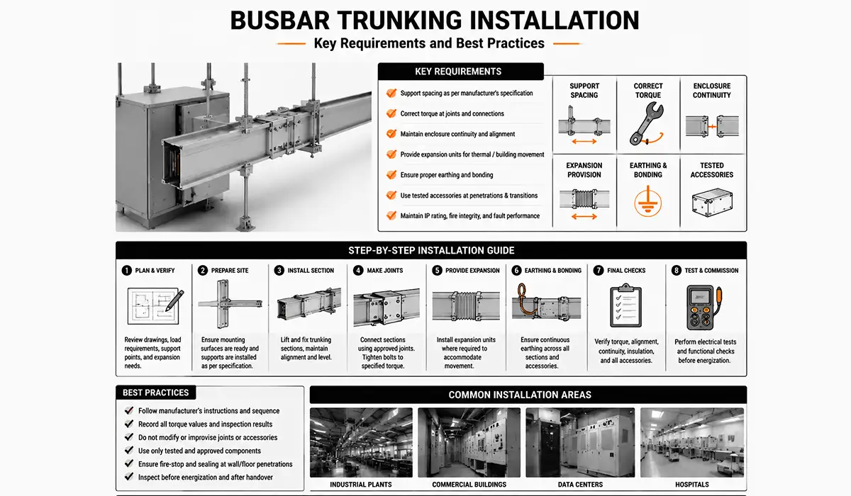
Busbar Trunking Installation — Key Requirements and Best Practices
Electrical busbar trunking installation quality has a direct effect on safety and compliance. Even a fully verified product can underperform if joints, supports, expansion provisions, or earthing paths are assembled incorrectly.
Good practice centers on support spacing, correct torque at joints, enclosure continuity, and clean alignment before energization. Expansion units are also needed where thermal movement or building movement can accumulate along long runs.
Installers should treat tested accessories as part of the system, especially at wall penetrations and environmental transitions. Mixing untested parts can compromise IP rating, fire integrity, or fault performance.
For teams searching busbar trunking system installation guide step by step, the practical answer is simple: follow the manufacturer’s sequence exactly, record torque and inspection checks, and never improvise joints or fire-stop details.
Busbar trunking installation quality is closely connected to safety practices used in busbar manufacturing more broadly, including surface preparation and jointing discipline. Reviewing the compliance principles applied during manufacturing can help installation teams maintain the same standards on site. This article on LV switchgear busbars is a recommended resource.
Support and Fixing Requirements
Support and fixing rules depend on product weight, current range, seismic requirements, and run orientation. Manufacturer examples commonly show support intervals in roughly the 1.5 m to 3 m range, and expansion joints must be mounted so longitudinal movement can occur without overstressing the enclosure or joints.
For a more detailed breakdown, download the complete guide here.
Support and fixing requirements for busbar trunking are easier to plan correctly when current busbar pricing and product availability are understood at the procurement stage. Comparing support hardware and accessory costs against the main run helps avoid budget surprises later. This article on busbar prices offers a useful overview.
Fire Compartment Penetration Requirements
Busbar trunking fire rated installation requirements are not satisfied by any generic sealant. Fire compartment penetrations need tested systems and installation details that preserve the building’s compartment rating; BSI even publishes a dedicated assessment method for cast-resin busbar trunking used on life-safety and fire-fighting supplies.
You can access the full PDF version of this reference from the link here.
Fire compartment penetration requirements for busbar trunking also intersect with how busbars are bent and routed through tight enclosure transitions. Correct bending technique at penetration points helps preserve both fire-stop integrity and conductor performance. This article on busbar bending techniques covers minimum radii and fabrication practices.
Applications of Busbar Trunking Systems — Where and Why They Are Used
BTS delivers its strongest value where cable trays become crowded, reconfiguration is frequent, or vertical risers are tight. That is why busbar trunking for industrial buildings and high-load commercial projects keeps gaining ground.
In data centers, dense rack loads and changing power maps favor plug-in runs with fast branch access. Schneider explicitly positions Canalis for high-density, scalable distribution, especially in data centers.
In high-rise buildings, rising main busbar systems replace large bundles of multicore feeder cable in shafts and simplify floor-by-floor distribution. In factories, the same plug-in logic helps machine tools move without full recabling.
Hospitals, harsh industrial sites, and some renewable installations also benefit when short-circuit performance, cleanliness, fire performance, or installation speed matter more than lowest first cost. BTS is not universal, but it is highly effective in these use cases.
Applications of busbar trunking in industrial and commercial buildings often rely on Victron-style busbar configurations for DC distribution in renewable energy installations. Understanding how these specialized busbars are used can be valuable when BTS interfaces with battery or solar systems. This article on Victron busbar explains this application area.
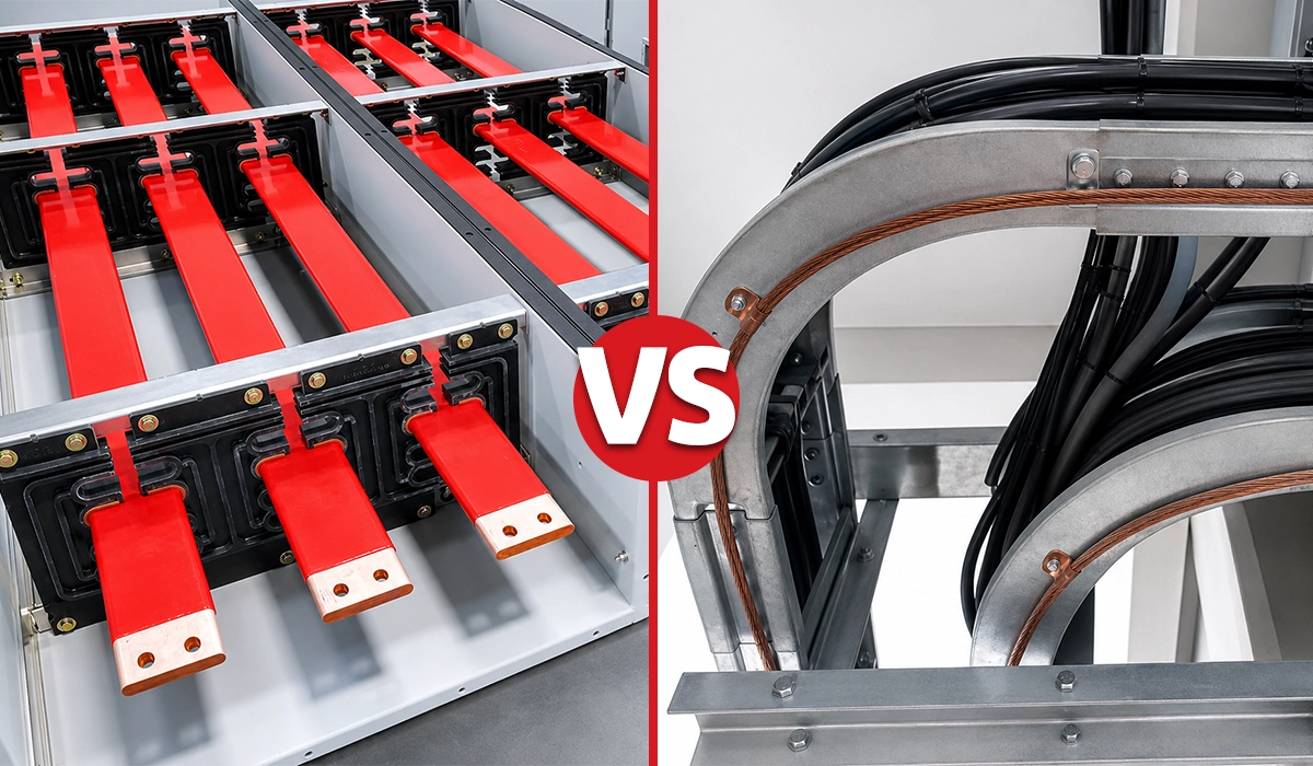
Busbar Trunking vs Cable — A Practical Comparison
The phrase busbar trunking vs cable should be treated as a design decision, not a slogan. Both solutions are valid; the correct choice depends on current density, route complexity, and how often loads will change.
Busbar usually wins when you need compact power density, repeatable factory joints, and fast modifications. Cable often wins in short, simple, low-current runs where containment is easy and future changes are unlikely.
Lifecycle economics are where BTS often pulls ahead. A higher upfront assembly cost can be offset by lower labor, cleaner routing, and simpler reconfiguration over the building’s service life.
That is why the real question behind busbar trunking system vs cable tray which is better is this: are you optimizing for first purchase price, or for long-term electrical flexibility and maintainability?
| Criterion | Busbar Trunking System | Traditional Cable Installation |
|---|---|---|
| Installation speed | Fast, prefabricated, bolted assembly | Slower, pulling and terminating conductors |
| Space requirement | Compact, especially sandwich type | More tray, conduit, or shaft space |
| Flexibility for load changes | High, tap-off relocation is simpler | Low, re-pulling or re-terminating is common |
| Short-circuit withstand | Strong, type-tested as an assembly | Depends on cable and protection coordination |
| Upfront cost | Usually higher | Usually lower |
| Lifecycle cost | Often lower where layouts change | Often higher when modifications are frequent |
| Voltage drop on long runs | Typically lower in compact systems | Often higher for equivalent layouts |
| Fire performance | System accessories available | Depends heavily on cable type and fire-stop details |
This comparison summarizes the most consistent technical and installation differences described by ABB, Eaton, and Siemens busway documentation.
The busbar trunking versus cable comparison ultimately depends on accurately sizing the conductors involved, particularly for copper busbar work where bending and cross-section calculations affect both options. This article on copper busbar bending provides calculation guidance relevant to both busbar and cable transition points.
Conclusion about Busbar Trunking Systems
Busbar trunking systems are no longer a niche alternative; they are a mature, standardized method for moving and distributing power in demanding facilities. This Busbar Trunking Systems Overview shows why specification quality matters as much as product choice.
The right selection starts with the application: sandwich, air-insulated, plug-in, and feeder systems solve different problems. Copper vs aluminum, indoor vs outdoor, and IEC vs UL choices should be made from project conditions rather than habit.
Engineers who size for current, fault level, voltage drop, enclosure rating, and future modification will usually get better lifecycle results than teams focused only on first cost. That is the central advantage of modern busway thinking.
As buildings become denser and power distribution becomes more dynamic, the structural advantages of tested modular busbar systems will remain strong in industrial, commercial, and critical-power environments.
Since busbars play a crucial role in the production of electrical panels, obtaining more information about power factor can be very important and essential for anyone designing busbar trunking systems for efficient power distribution.