




If you’d rather listen than read, feel free to play the audio file below for the rest of this article.
Why Arc Furnaces Run on Low Voltage and Huge Current
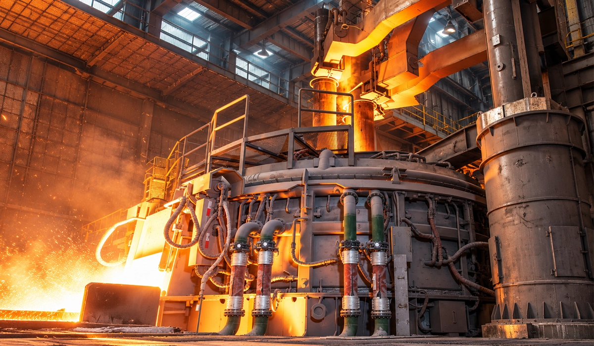
So, why does an EAF use low voltage and high current? An arc only holds a few hundred volts, and longer, higher-voltage arcs throw heat at the walls and roof. Every electric arc furnace busbar therefore runs at low voltage, so the current must climb into the tens of kA.
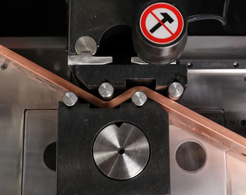
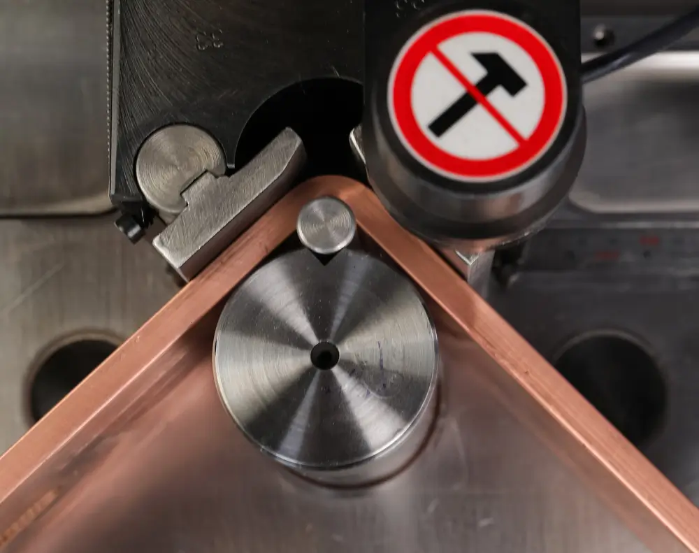
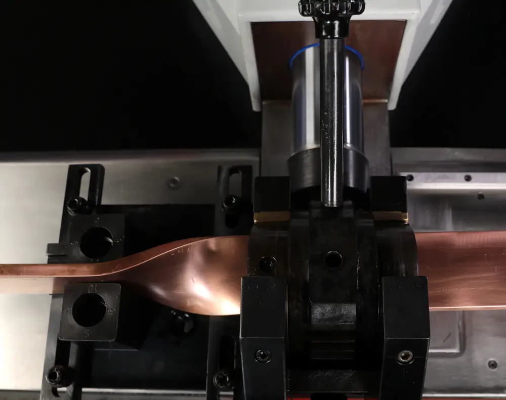
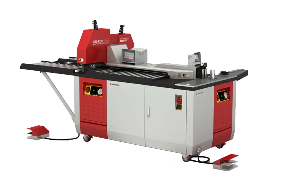
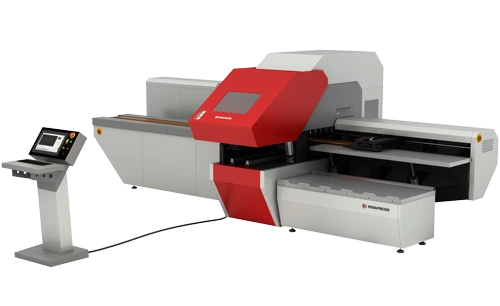
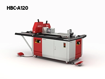
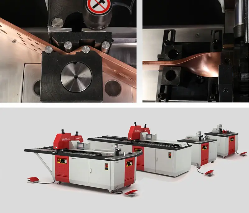
The PAYAPRESS HBC-B120ES combines cutting, punching, and bending operations for copper and aluminum busbars up to 120 × 12 mm. With its programmable positioning system, it delivers precise and efficient busbar fabrication for electrical switchgear and panel manufacturing.
The Path from Transformer to Electrode
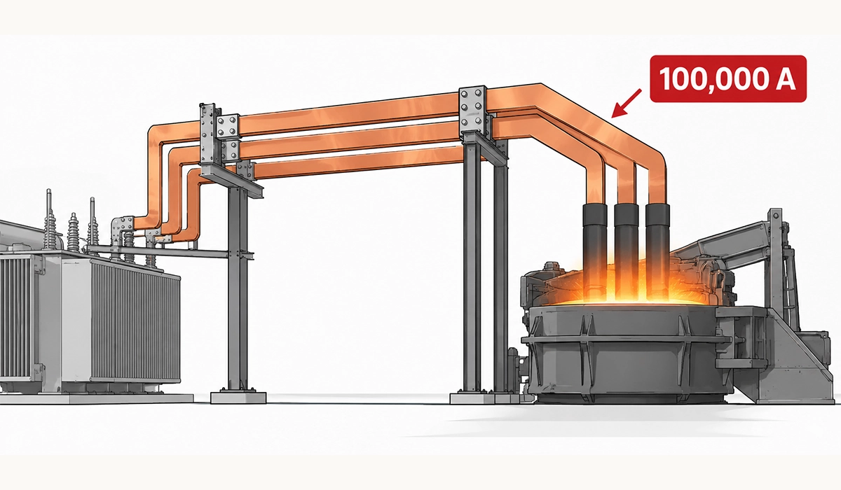
The EAF power supply usually starts from a high-voltage grid connection. First, a step-down transformer often brings it to a medium voltage, such as 30 kV (typical value). Next, the furnace transformer cuts the voltage to well under 2 kV and raises the current in the same ratio.
Its low-voltage side then feeds the electric arc furnace secondary circuit, which engineers often call the short network. This chain of bars, cables and tubes runs from the transformer terminals to the graphite electrodes. Finally, the current jumps from each electrode tip to the steel through the arc. Because the short network is heavy and close to the furnace, its layout decides how much transformer power actually reaches the arc.
Furnace short networks are an extreme case of the busbars found in every power distribution system. For the fundamentals of busbar types, design and applications, see our guide to power distribution busbars.
Where 100,000 Amps Comes From
So, how much current does an electric arc furnace use? The answer follows from a simple rule: power equals voltage times current. For a three-phase transformer, current equals apparent power divided by √3 times the secondary voltage. For example, a 150 MVA unit at 900 V delivers about 96,000 A per phase (hypothetical estimate). In contrast, the same unit at 1,500 V delivers about 58,000 A (hypothetical estimate). In other words, lower voltage means higher current for the same power. Halving the voltage doubles the current and quadruples the resistive heat in every conductor. Large steelmaking furnaces therefore often run at 60–120 kA per electrode (typical range), while small ladle furnaces draw far less.
Anatomy of the Secondary Circuit
So, what is the secondary circuit of an arc furnace? It is every conductor between the transformer’s low-voltage terminals and the electrode tips. Good arc furnace secondary circuit design keeps this path short, balanced and well cooled, because every small loss here repeats on every heat.
Calculation papers split the circuit into parts so that engineers can check heat, stress and impedance one by one. For instance, a 2019 study of a 110-ton furnace lists seven elements, from the transformer secondary to the electrode clamping ring, in its secondary circuit study.
The secondary circuit is one specialized way of arranging conductors between a source and a load. Compare it with the common layouts in our guide to busbar arrangements.
Delta Closure and Flexible Cables
Furnace transformers usually have delta-connected secondary windings, and the delta closure is the set of bars that joins them. Designers close the delta either at the transformer or near the furnace, and on large units the closure is often water-cooled. From there, flexible cables carry the current to the moving parts. They must flex, because the electrode arms rise and fall and the furnace tilts to tap. Large furnaces typically use water-cooled cables, with copper strands inside a hose that carries the cooling water (typical; varies by design). As a result, the cables stay cool, although every bend cycle slowly fatigues their strands.
Water-Cooled Bus Tubes
Next, the current reaches the EAF bus tubes, rigid copper tubes that run along or above each electrode arm. So, why are furnace bus tubes water-cooled? First, they sit just above a furnace that radiates intense heat. Second, they carry tens of kA, so resistive heating is high. Water flowing through the bore removes both heat loads and keeps the copper at a steady temperature.
In addition, a tube suits AC current well. At 50 Hz, skin effect pushes most of the current into roughly the outer 9 mm of copper, so a solid core would add weight but carry little current. Water-cooled bus tubes therefore put copper where the current flows and water where the copper would sit idle. As a result, a compact tube can carry far more current than a solid bar of the same weight.
Electrode Arms and Contact Clamps
Each EAF electrode arm holds one graphite electrode and moves it up and down to control arc length. On older designs, separate bus tubes ride on a steel arm. Many modern furnaces, however, use current-conducting arms made of copper-clad steel or aluminum, which carry the current themselves.
At the arm tip, the electrode holder grips the electrode. Copper contact clamps, also called contact pads, press against the graphite with high spring force, while hydraulics release them so operators can lower the electrode as its tip burns away. That contact face is the last joint in the circuit, and it carries the full phase current. If dirt, wear or low clamping force raises its resistance, the pad overheats and can even arc against the electrode.
Design Challenges at Extreme Current
At these currents, effects that stay tiny in a switchboard become design limits. A high current busbar in a furnace bay must handle current crowding, large magnetic forces and phase imbalance at the same time.
Spacing rules for round tubes rarely appear outside patent text, so the original filings remain a useful reference. For example, a 1979 Lectromelt patent explains why rectangular bars carry current unevenly and states the usual tube spacing in its bus bar patent.
The same magnetic forces that shake furnace bus tubes also test panel busbars during faults. Learn how engineers check bars and supports in our article on short-circuit withstand.
Proximity Effect and Spacing
Skin effect pushes AC current toward the outside of a single conductor. Proximity effect, in contrast, pushes it toward one side when another conductor sits close by, because each conductor’s magnetic field acts on its neighbor. The busbar proximity effect arc furnace designers face is severe, since the currents are huge and the conductors run close together.
For example, a US patent on arc furnace bus bars notes that designers usually space round tubes at least 2.25 times the tube diameter apart to avoid harmful current redistribution. The same patent explains that in rectangular bars, current tends to flow along only one surface. As a result, part of the copper does little work while the loaded face runs hot. Therefore, round tubes and rectangular bars are not interchangeable here.
Electromagnetic Forces and Thermal Stress
Parallel conductors push or pull on each other, and for equal currents the electromagnetic force grows with the square of the current. For example, two conductors 0.5 m apart, each carrying 100 kA, feel about 4 kN per meter (hypothetical estimate). With AC, that force pulses at twice the supply frequency, so supports and joints face constant vibration. During electrode short circuits, such as scrap cave-ins, the current can rise several times above normal, and the force rises even faster. Meanwhile, ampacity depends on temperature, and every heat cycle expands and shrinks the copper. Therefore, clamps, spacers and bolted joints need a fatigue-resistant design, not just static strength.
Reactance and Balance Between Phases
In the short network, reactance (the AC opposition caused by magnetic fields) is far larger than resistance. For example, the 110-ton furnace study lists about 3.5 mΩ of reactance against 0.6 mΩ of resistance in the secondary circuit. Reactance limits current and sets the power factor, so designers manage it rather than simply minimize it. However, problems start when the three phases see different reactance. In a flat layout, the middle phase sits between its neighbors and couples with them differently from the outer phases. As a result, one phase can deliver more arc power than the others, which wears electrodes and refractory unevenly. Many furnaces therefore arrange the conductors in a triangle to balance the three phases.
Materials and Fabrication of Furnace Busbars
So, what material is used for furnace busbars? Copper leads, because it combines high conductivity, strength at temperature and a conductive oxide film. Aluminum appears in some current-conducting arms, where its low weight helps the arm move quickly. However, copper vs aluminum in the main bars and tubes usually favors copper, since space near the furnace is tight and joints must survive heat. Even so, an arc furnace copper busbar or tube still needs the right grade (typical choices; confirm per project).
| Grade (EN / UNS) | Typical use in the short network | Fabrication note |
|---|---|---|
| Cu-ETP (CW004A / C11000) | Delta bars and bolted connection bars | Very high conductivity; risks embrittlement when welded or brazed |
| Cu-OF (CW008A / C10200) | Bus tubes and welded or brazed parts | Most weldable copper; conductivity close to Cu-ETP |
| Cu-DHP (CW024A / C12200) | Cooling-water fittings and some tube work | Welds well, but conducts noticeably less current |
At PAYAPRESS, we build machines that cut, punch and bend busbars, and copper busbar fabrication for furnaces pushes every machine to its limit. Heavy sections come first. Delta bars and connection plates often run 10–20 mm thick and 100 mm or wider (typical; varies by design). For these, a hydraulic shear or a cold saw gives a square, burr-free cut, while a worn blade leaves a rolled edge that spoils the joint face. Tubes, in contrast, need a saw, because a shear crushes the bore.
Bending comes next. Flat bending of soft copper typically allows an inside radius of about one bar thickness, while edgewise bending of wide bars needs much larger radii to avoid buckling (typical; confirm per grade and temper). Bus tubes are harder still. Without internal support, a tube flattens or kinks in the bend, which cuts water flow and creates a hot spot. Therefore, good practice is to bend tubes over a mandrel or with a filler, then check ovality after each bend.
Finally, drilling and joint preparation decide contact resistance. In our experience, thick bars need drilled rather than punched holes once the hole diameter falls below the bar thickness. Contact faces should be flat, deburred and cleaned just before assembly. Many furnace joints are also machined flat or silver-plated (typical; varies by design), because a single micro-ohm at 100 kA turns into about 10 kW of heat. Welded and brazed joints, meanwhile, need the right grade and preheat, since copper draws heat away from the weld quickly.
Grade choice matters most where tubes and fittings must be welded or brazed into a water circuit. TWI’s guidance explains why oxygen-free copper welds most readily and why tough pitch grades risk embrittlement in its copper welding guide.
Bend radii and springback matter just as much on heavy delta bars as on panel busbars. Our guide to bending copper busbar covers minimum radii and fabrication tips in detail.
Cooling Systems
Cooling turns a conductor that would overheat into one that runs all day. A water-cooled busbar for arc furnace duty usually belongs to a closed loop that also serves the delta closure, the flexible cables, the bus tubes, the contact pads and often the arms (typical; varies by design). Pumps drive treated cooling water through each circuit, and a heat exchanger then rejects the heat.
Water quality matters as much as flow. The water links parts at different potentials through insulated hoses, so many plants limit its conductivity to cut leakage current and corrosion (typical practice). In addition, scale and debris narrow the bores and reduce heat transfer, so filters and regular flushing help. Each circuit also needs flow and outlet temperature monitoring, because a falling flow or a rising temperature difference warns of a blockage before the copper overheats. Many plants also fit flow switches that alarm or trip the furnace when a circuit loses water.
Leaks, however, are the real danger. Water that reaches molten steel can turn to steam explosively, so leak detection and fast isolation valves protect both people and the furnace. For the electric arc furnace busbar itself, a slow leak also wets insulation and speeds corrosion at the joints.
Transformer suppliers cool the low-voltage connections too, because the heat starts before the current even leaves the tank. GE Vernova’s brochure describes bushings with internal water tubing for very high secondary currents in its transformer cooling details.
Cooling is what lets a compact conductor carry far more current than its size suggests. To see how current, temperature rise and cross-section connect, read our busbar sizing guide.
Arc-Fault Protection
So, what causes busbar failure in arc furnaces? Loose or dirty joints overheat, water leaks wet the insulation, and constant vibration fatigues supports and cable strands. Conductive dust adds a further risk, because it settles on insulators and bridges the gaps between conductors. Once an arc forms between two conductors, it can release enormous energy within seconds.
A 2023 study of an ore furnace shows how fast this happens. There, each transformer section feeds a pair of water-cooled copper bus tubes 20–40 mm apart, wrapped in fiberglass cloth, with operating currents of 35–150 kA. The authors found that abrasive dust wears through the insulation wrap, while coal dust can form conductive bridges between the tubes. An arc fault can then destroy the whole assembly within one to three seconds.
Arc fault protection for furnace busbars is difficult, because the fault current may not rise far above the normal load. As a result, standard overcurrent relays may not trip, and current transformers large enough for differential protection are costly. The study therefore proposes a current-based method that senses the busbar’s magnetic field instead. In a healthy assembly, the field around the paired tubes stays symmetrical. However, an arc between any pair upsets that symmetry, so a sensor near the bus detects the fault. Other plants rely on optical arc-flash sensors, differential relays or Rogowski coils, and the right mix depends on the layout. Whatever the method, fast tripping matters most, because the damage grows with every cycle the arc burns.
Paired-tube layouts appear in many high-current furnaces, so the failure modes in this study apply beyond ore smelting. The open-access paper models the field pattern and checks it against measurements on a 16,000 kVA unit in its arc fault study.
Many arc faults start where dust or moisture shrinks the gap between conductors. Our article on busbar clearances explains how spacing rules keep phases safely apart.
Inspection and Maintenance
Good furnace busbar maintenance catches small faults before they become arc faults or forced outages. Most checks fit into scheduled furnace stops, while thermography and cooling data can run during operation (typical practice).
| Area | What to check | Warning signs |
|---|---|---|
| Bolted joints | Torque, contact faces, plating wear | Discoloration, loose bolts, rising temperature |
| Contact clamps | Pad faces, spring force, cleanliness | Arc marks, pitting, uneven wear |
| Cooling circuits | Flow, outlet temperature, hoses, fittings | Leaks, low flow, scale, damp insulation |
| Flexible cables | Hoses, strands, end fittings | Kinks, bulges, broken strands, hot ends |
| Insulation | Wraps, spacers, insulators | Abrasion, cracks, dust build-up |
| Thermography | Infrared scan of joints, pads and tubes | Hot spots or rising temperature trends |
| Supports | Clamps, spacers, welds | Cracks, loose fixings, vibration damage |
Thermography works best as a trend rather than a single snapshot. For example, a joint that runs clearly hotter than similar joints under the same load deserves a closer look, even while it stays within limits. Similarly, micro-ohm readings taken during shutdowns give each joint a baseline, so a rising value flags trouble early.
Dust control belongs on the list too. Regular cleaning of insulators, wraps and spacers removes the conductive film that invites tracking and, eventually, arcs.
General maintenance standards set a minimum rhythm for these checks, although furnace plants usually inspect far more often. TÜV SÜD summarizes the NFPA 70B 2023 rules, including thermography at least every 12 months, in its NFPA 70B overview.
Inspection intervals and test methods often trace back to formal busbar requirements. For an overview of the key rules, see our guide to busbar standards.
Conclusion: Electric Arc Furnace Busbars
Carrying 100,000 A takes more than a large copper section. The electric arc furnace busbar circuit must manage skin and proximity effects, magnetic forces, phase balance, cooling and dust all at once. Choose the right grades, fabricate carefully, protect against arc faults and inspect on a steady rhythm, and the short network will deliver power reliably for years.
Many of the same principles, from grade choice to joint plating, also apply to smaller high-current installations. Find out when a silver plated busbar is worth its extra cost.


Rate this article
Choose a rating from 1 to 5 stars.
No ratings yet