



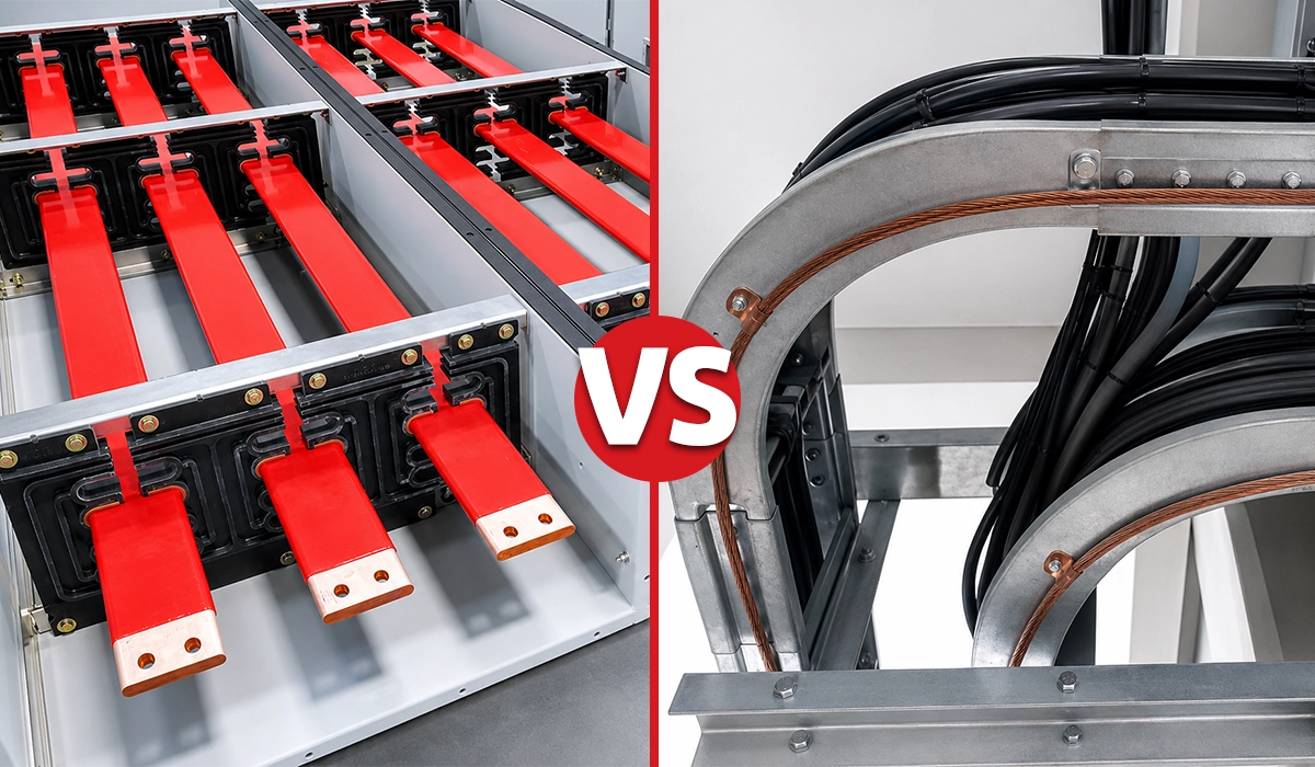





Why Use Busbar Instead of Cable or Wire?
Busbars replace cable for one reason above all others: at high current, cable stops scaling. Everything else follows from that.
Past roughly 630 A, a single cable set can no longer carry the load, so the designer runs cables in parallel — four, six, sometimes eight per phase. And parallel cables bring problems that a single conductor does not have:
Every added cable makes the bundle hotter. Cables in a group heat each other, so a grouping derating factor applies to the whole bundle. Adding the sixth cable does not add a sixth of the capacity.
Current does not share itself equally. Small differences in cable length or termination resistance push more current down one path than another. Every parallel set needs checking, and the check has to hold for the life of the installation.
The labor multiplies, not adds. Six cables per phase means eighteen pulls, eighteen sets of cleats, and thirty-six terminations. Each one is a chance to get phasing or torque wrong.
The tray infrastructure grows with it. More cables means wider tray, more supports, more steelwork, and more space in a room where space is usually the constraint.
A busbar system removes all four at once. One enclosure, one conductor per phase, factory-fixed phasing, a type-tested rating, and bolted joints instead of terminations.
A note on wording: “wire” and “cable” are often used interchangeably here, but in distribution work the comparison is really busbar against cable — insulated conductors sized for power circuits. Wire generally means smaller single conductors used for control and branch wiring, where busbar was never a candidate. The engineering question is the same either way: at what current does a flexible conductor stop being the sensible answer?
What Are Busbar Systems?
A well-specified busbar trunking system distributes up to about 6,300 A in a single enclosed assembly, with the largest commercial busway families reaching that range. IEC 61439-6 is the standard that governs these systems — it does not set a current ceiling, but it defines the construction requirements and the design verification that a manufacturer must complete for whatever rating is claimed, using rigid copper or aluminium conductors in a prefabricated, phase-segregated housing.
In any busbar vs cable specification, the system architecture is the starting point. The busbar system — busway, bus duct, or busbar trunking system — uses rigid copper or aluminium conductors in a flat or edge-on arrangement inside a protective enclosure. Conductors are chosen for current rating, weight, and installed cost. The enclosure segregates phases and contributes to short-circuit withstand performance.
Busbar trunking systems come in a modular, prefabricated format. Sections bolt together on site without field-fabricated joints. Tap-off units attach at fixed positions, suiting switchgear rooms, data centers, substations, and production lines where loads are distributed along a common route.
Busbar systems are one part of the broader family of electrical busbars used across power distribution systems, from LV panels to large industrial installations.
Bus Duct vs Cable: Is It a Different Comparison?
Mostly no, but the terms are worth pinning down because they are used differently by region.
Bus duct usually means an enclosed, high-current run between major equipment — transformer to switchgear, generator to main board. It is a point-to-point connection, often at very high current, and frequently has no tap-offs at all.
Busbar trunking or busway usually means a distribution run with tap-off points along its length, feeding loads as it goes.
Against cable, bus duct wins on the same grounds as busway, only more sharply. A transformer-to-switchgear link at 4,000 A would need eight or more cables per phase, and the termination work at both ends is substantial. A single bus duct run replaces all of it with two connections. Where bus duct differs is that the flexibility argument barely applies — there is nothing to tap off — so the decision comes down almost entirely to current, space and termination labor.
What Are Cable Systems?
A cable power distribution system provides a proven path for circuits up to approximately 630 A per cable set. IEC 60364-5-52 governs how current-carrying capacity is derived for insulated conductors in trays, conduits and buried ducts. In practice, most designers treat about 630 A as the point where a single cable set stops being sensible.
Cable systems use insulated single-core or multicore cables in trays, conduits, or buried ducts, with terminations at both ends. For high-current work, designers add parallel cables per phase. Familiar to contractors and easy to procure, they suit smaller loads, irregular routes, and long-distance underground runs.
Cable systems ultimately feed into distribution boards that receive and distribute power to final circuits. Understanding the types of electrical power distribution boards available helps clarify where cable systems connect to the broader distribution hierarchy.
Cable runs terminate somewhere: our guide to distribution board types covers what sits at the end of the run.
Busbar vs Cable: The Key Differences at a Glance
The busbar vs cable comparison becomes concrete when both systems face the same engineering criteria. On high-current projects, busbar trunking vs traditional cable distribution can reduce switchgear room floor space by 40–50%. Manufacturer field studies attribute this to consolidating phase conductors and mechanical support into a single enclosed assembly.
| Factor | Busbar Systems | Cable Systems |
|---|---|---|
| Space requirement | Compact — one enclosure per circuit | Multiple trays, supports, and cable sets |
| Installation speed | Faster — prefabricated, bolted sections | Slower — pulling, cleating, termination |
| Current capacity | Up to 6,300 A in a single assembly | Parallel runs needed above ~630 A |
| Safety | Enclosed conductors, defined IP rating | Site-installed; routing errors are possible |
| Maintenance | Accessible, clearly segregated phases | Complex in high-density cable routes |
| Scalability | Tap-off units added without full rewire | Expansion needs new cable pulls and tray capacity |
| Initial cost | Higher for the busway assembly | Lower for simple or low-current work |
| Lifecycle cost | Lower where labor, space, and expansion matter | Can rise significantly with future modifications |
Why Busbars Beat Cables: Six Practical Advantages
Busbar system advantages in industrial electrical applications are most visible in high-current, high-density, or frequently modified projects. The busbar trunking system advantages over cable translate into lower project delivery time, lower maintenance burden, and better expandability — measurable across installation labor, maintenance access, and future expansion cost.
The advantages of busbar systems over cable become even clearer when viewed through the lens of how busbars function inside LV switchgear panels, where the same principles of compact current distribution and defined phase segregation apply at a smaller scale.
Higher Current Capacity
A busbar system delivers its rated current in a single enclosure without the grouping derating that banked cable sets require. That rating is not estimated on site — under IEC 61439-6 the manufacturer must verify temperature rise by design verification before the system ships.
The case for busbar vs cable for high current applications is clearest above 800 A. A single busway assembly carries 3,200 A or more. The equivalent cable system needs four to six cables per phase at that current level. Each set requires its own tray, termination, and a current-sharing check at every joint.
Parallel cable runs demand precise attention to current balance. Length differences or termination resistance variations cause uneven loading between parallel sets. Busbar conductor geometry eliminates that variable.
Higher current capacity in busbar systems requires correct sizing to match both continuous current and short-circuit withstand requirements. The sizing methodology that governs this decision applies to both busbar trunking and individual panel busbars.
Whichever system you pick, the rating has to be derived properly — see busbar sizing by current and temperature rise.
Space-Saving Design
In switchgear rooms, plant rooms, and data centre risers, space is a real constraint. A single 2,000 A busway section occupies a fraction of the cross-section of an equivalent cable bundle. Tray structures, individual cleats, and pull-box arrangements disappear. This matters most in riser shafts and congested plant rooms where the electrical zone competes with HVAC, pipework, and structural steelwork.
Space-saving busbar design depends heavily on maintaining correct clearances between conductors and enclosure walls.
Faster Installation
The installation labor difference comes from what each system asks the site team to do. A busway run is a sequence of bolted joints between prefabricated sections. The equivalent cable route means pulling four to six cables per phase, dressing each to tray, cleating at the required intervals, and making every termination twice — once at each end. Above 1,000 A the termination work alone can run into days. That is where the hours go, and it is why the gap widens as current rises rather than staying proportional.
Bolting prefabricated sections together and connecting plug-in units is faster than pulling multiple heavy cables, dressing them to tray, cleating at required intervals, and making every termination. The saving is most significant above 1,000 A, where termination work alone runs into several days.
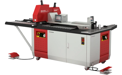
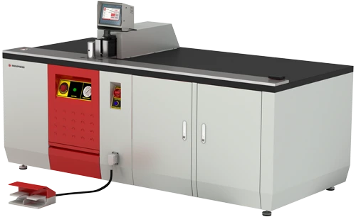
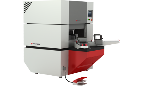
Faster installation of busbar systems also depends on accurate fabrication of the busbar conductors themselves, since sections that are cut, punched, or bent out of tolerance create rework on site.
Better Heat Dissipation and No Grouping Derating
A correctly rated busbar enclosure maintains conductor temperature within IEC 61439 temperature-rise limits at full rated current. Type-testing verifies this by confirming heat distribution across the full conductor surface, not just at grouped cable centre-cores.
In dense cable routes, center cables in a grouped arrangement run hotter than outer cables. This forces a grouping derating factor, reducing usable current capacity across the entire bundle. Busbar conductors have defined, type-tested thermal performance — factory-validated before delivery. That removes a layer of thermal uncertainty that cable derating always carries on site.
Heat dissipation performance in busbar systems is closely related to how power factor is managed across the installation, since reactive current contributes to conductor heating and affects the thermal margin available at rated current.
Easier Expansion
Plug-in busbar tap-offs allow new load connections along the busway without removing the assembly or interrupting adjacent circuits. IEC 61439-6 sets the requirements that tap-off units must meet and the verification they must pass; where the sockets sit along the run is the manufacturer’s design choice, and it is worth confirming at specification stage.
When a production line adds a machine or a data center adds a rack row, a plug-in system absorbs the new load at an existing tap-off position. The busbar trunking system vs cable alternative means routing new cables to the source board, locating tray capacity, and managing a planned outage. On facilities with a rolling capital program, that difference in expansion cost compounds quickly.
Easy expansion through plug-in tap-offs works best when the overall busbar arrangement has been planned with future load additions in mind from the outset. A structured comparison of single and double busbar schemes helps engineers choose the arrangement that best supports long-term flexibility.
Cleaner Layout and Easier Maintenance
Clear phase identification and accessible tap-off units replaced the dense, multi-layered cable bundle that made fault tracing slow.
Busbar system maintenance is more straightforward than cable maintenance in a dense route. The system is visible, labelled, and accessible. Thermal imaging and insulation resistance checks are quick. A fault buried under two layers of cables in a shared tray is genuinely difficult to trace. Busbar trunking makes the distribution path clear at every inspection point.
Cleaner layout and easier maintenance also depend on using well-designed busbar trunking systems that provide clear tap-off access and defined inspection points throughout the run.
Our busbar trunking guide covers how these systems are structured and maintained.
Where Cable Still Wins Over Busbar
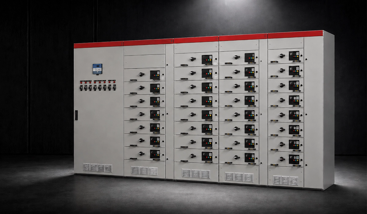
Cable systems deliver lower total installed cost for distribution circuits below approximately 400 A. Material and labor comparisons across standard industrial projects confirm this, where insulated conductors avoid the custom engineering and manufacturing lead time that busbar assemblies require.
For circuits up to 400 A — the bulk of branch-circuit work in most industrial plants — standard cable in a properly sized tray is cost-effective and fast to procure. Lead times are short and design tools are widely available.
Cable systems handle irregular routes that a rigid busway cannot follow. Underground distribution, installations that wind through plant structures, and long-distance runs to outlying equipment all suit cable well. Cable system disadvantages emerge at high current levels and in dense installations — not in standard branch-circuit work.
Where future expansion is unlikely and current ratings are modest, cable is the simpler, lower-risk choice.
Cable systems in low-current applications often use flexible busbars at transition points where the cable connects to a rigid bus or terminal bar inside a panel. Understanding the available flexible busbar types and their sizing standards helps engineers specify these transition sections correctly.
Busbar vs Cable Cost: Why Material Price Misleads
On industrial projects distributing above 1,000 A, the busbar system cost vs cable cost comparison consistently favored busbar on a total lifecycle basis. This calculation included parallel cable sets, tray infrastructure, labor, and future modification cost — not just material price.
The busbar system cost vs cable system installation cost comparison is often muddled by looking at material prices alone. Busbar assemblies cost more per meter — but total installed cost tells a different story on high-current projects.
Several factors shift the calculation toward busbar: installation labor, tray and support steelwork, termination hardware, future modification outage cost, and the maintenance burden in dense cable routes. Labor is the biggest driver — it rises steeply with cable count and parallel runs.
Cable systems look cheaper on a materials-only basis. Include labor, space, and lifecycle costs for a large industrial distribution system, and the gap closes — often inverting above 1,000 A. Never compare systems without a project-specific cost model.
A realistic cost comparison between busbar and cable systems should include current busbar material pricing as an input, since copper and aluminium prices fluctuate and directly affect the material cost side of the calculation.
Copper and aluminium move with the metal markets, so start from current busbar prices rather than last year’s estimate.
Busbar vs Cable Safety: Which Is Easier to Keep Safe?
How busbar systems improve electrical safety and reliability is measurable. Enclosed conductors, defined phase separation, and type-tested short-circuit ratings reduce fault risk, as verified against IEC 61439 and IEC 61140. These properties eliminate the wiring errors that dense cable installations introduce.
Both systems can be safe when correctly designed, installed, tested, and maintained. The engineering question is which system is easier to keep safe across its operational life.
Busbar systems enclose live conductors in a rated housing. Phasing is fixed and factory-tested. The short-circuit withstand rating is type-tested and documented. Inspection is straightforward because the system is organized, accessible, and clearly labelled.
Cable systems rely on correct routing, labelling, and termination on site. In dense installations with parallel runs, phasing errors, missed cleats, or undertightened terminations are possible — and the opportunity for error rises with system complexity.
Both require correct engineering, protection coordination, and maintenance. Selecting either system without a proper fault-level study is the more common safety failure on real projects.
Safety and reliability of busbar systems are directly tied to short-circuit withstand performance, which must be verified during the design stage against the available fault level at each point in the distribution system.
The rating that matters most here is short-circuit withstand, verified against the fault level at each point.
Where Busbar Systems Are Usually the Better Choice
Why use busbar instead of cable in factories becomes clear above approximately 800 A. Busbar systems vs cable systems for industrial power distribution consistently show faster installation, lower space consumption, and lower maintenance cost — across data center, manufacturing, and substation applications.
Busbar systems are the stronger technical and commercial choice for:
- Manufacturing plants and production lines with distributed machine connections along a common route.
- Switchgear rooms and panel feeders at 630 A and above.
- Data center busway risers matched to rack-row layouts, where plug-in flexibility matters.
- Substations with high-current connections between transformers and switchgear.
- High-rise building risers where shaft space is tightly constrained.
- Facilities with changing production layouts requiring regular load additions.
- Any busbar system for industrial applications where current level, space, and expandability align.
Busbar systems in manufacturing plants and switchgear rooms are particularly well served by a selection guide that ties busbar type to the specific requirements of LV panel applications. Using a structured selection framework prevents over- or under-specification at the panel-feeder level.
Where Cable Systems May Still Be the Better Choice
Cable system limitations in high current power distribution are real. Below approximately 400 A in stable installations, cable is the more practical choice. Lower total installed cost and faster procurement give cable the edge where custom busbar lead time is not justified.
Cable systems remain the right choice for:
- Individual circuits below approximately 400 A.
- Long-distance or underground distribution routes.
- Sites with irregular routing geometry that a rigid busway cannot navigate.
- Projects where initial budget is the primary constraint and expansion is not planned.
- Retrofit work where existing cable infrastructure is adequate and replacement is not justified.
Cable systems at the lower end of the current range often connect into terminal busbars inside panels, where the transition from flexible cable to rigid bus must be correctly specified and rated. Understanding how terminal busbars are designed and applied helps engineers manage this connection point safely.
How to Choose Between Busbar and Cable: A Decision Matrix
Selecting busbar vs cable without a load schedule and site layout in front of you is a specification risk. Applying defined thresholds at the design stage prevents costly redesign later.
| Decision Factor | Choose Busbar When… | Choose Cable When… |
|---|---|---|
| Current rating | Above ~630–800 A per circuit | Below ~400–630 A |
| Space | Constrained — plant room, riser, switchgear | Open route; tray space is available |
| Installation time | Program is tight | Timeline allows conventional installation |
| Future expansion | Load additions expected within 5–10 years | Layout fixed; expansion is unlikely |
| Route geometry | Straight or gently curved runs | Irregular, long-distance, or underground |
| Maintenance access | Regular inspection required | Route accessible; cable density is low |
| TCO priority | Lifecycle cost drives the decision | Initial capital cost is the main constraint |
The crossover is never a single number. It combines current level, route geometry, program pressure, and future plans. Work through the decision matrix above with real project data before committing to either system.
Making the right choice between busbar and cable also benefits from using dedicated busbar design software that models current density, derating, and voltage drop for candidate configurations before the decision is locked.
Final Verdict: Busbar Systems vs Cable Systems
For industrial and commercial distribution above approximately 800 A, busbar vs cable is not a close call. Busbar systems deliver lower total cost, faster installation, and better scalability — demonstrated across switchgear, data centers, and manufacturing sites — through factory-engineered assemblies, compact enclosures, and modular expansion points.
For modern industrial power distribution where current ratings are high, space is limited, future changes are expected, and reliability is non-negotiable, busbar systems are the stronger technical and commercial choice. Their advantages in installation speed, space efficiency, and scalability compound across a 20-to-30-year asset life.
Cable systems are not obsolete — they are the right choice for simpler, lower-current, or geographically complex installations. Base the decision on load data, lifecycle cost, and expansion requirements, not convention.
The same trade-off appears at panel-feeder level — see busbar in electrical panels.




Rate this article
Choose a rating from 1 to 5 stars.
No ratings yet