






If you’d rather listen than read, feel free to play the audio file below for the rest of this article.
Quick-Reference Busbar Torque Table (M6–M16)
This busbar torque chart gives dry-thread values for high-tensile steel (grade 8.8) or aluminium bronze fasteners on copper busbar. Read it as a busbar bolt torque nm chart for checking a design, not as a substitute for the connector or switchgear manufacturer’s own spec sheet. Busbar bolt tightening torque is a specified value, not a derived one.
| Bolt size | Copper busbar torque (CDA Table 22) | Bar width and bolt count it belongs to | Generic ISO 898 Gr. 8.8 steel torque (dry) | Busbar figure as share of steel figure |
|---|---|---|---|---|
| M6 | 7.2 Nm | 16–20 mm bar, 2 bolts | 9–12 Nm | ~0.6–0.8× |
| M8 | 17 Nm | 25–30 mm bar, 2 bolts | 22–29 Nm | ~0.6–0.8× |
| M10 | 28 Nm | 40 mm bar (2 bolts), 60 mm bar (4 bolts) | 45–57 Nm | ~0.5–0.6× |
| M12 | 45 Nm | 50–120 mm bar, 2–5 bolts | 77–100 Nm | ~0.45–0.6× |
| M16 | 91 Nm | 160–200 mm bar, 6–8 bolts | 190–248 Nm | ~0.4–0.5× |
Two things stand out. Every busbar figure sits below the structural figure for the same bolt. And the third column matters as much as the second, because CDA ties each torque to a bar width, an overlap and a bolt count, not to bolt size alone.
If you would like to explore this subject further, you can read more about it here.
Why a Regular Bolt Torque Chart Is the Wrong Tool for Busbar Joints
A structural torque chart answers a different question. It tells you how to load a bolt close to its proof strength so two steel plates cannot slip relative to each other. That is a mechanical objective, and the bolt is the component being optimised. Nothing in that calculation concerns electricity.
For anyone who wants to review this later without an internet connection, the offline version is available to download.
A busbar joint has an electrical objective. What matters is contact pressure across the overlap area, held stable through years of load cycling. CDA data shows contact resistance falling rapidly as pressure rises, but flattening out above roughly 30 N/mm², with 10 N/mm² and above the preferred working range. Past that point, extra torque buys almost no electrical improvement.
That is the core of the busbar bolt torque table above: you tighten to reach a contact pressure, then stop. Copper busbar bolt torque is bounded from above by the bolt, not by the bar.
One widespread claim needs correcting here. It is often said that structural torque figures will crush or cold-flow a copper bar. CDA states the opposite: because of the strength of copper, deformation of the conductor under joint pressure is not normally a consideration. For a what-is-busbar, the risk profile differs by material — cold flow is a genuine concern in aluminium and a minor one in copper.
So what does over-torquing actually damage on a copper joint? Not the bar, in most cases. The bolt. CDA’s guidance is that bolt tension must stay below 95% of yield at any temperature in the working range. Differential expansion between a steel bolt and a copper bar raises tension as the joint heats. A joint tightened to a structural figure at 20 °C can exceed the bolt’s safe stress at 90 °C, yield slightly, and come back cooler and looser than it started. Copper creep plays a smaller part in the same story. The failure is delayed, which is what makes it easy to miss.
What Actually Sets the Right Torque for a Given Joint
Bolt size is only the first of five variables in an electrical busbar torque specification. Change any of the others and the correct number changes with it. That is why two identical M10 bolts, in two panels, can carry legitimately different torque figures. The four subsections below take the remaining variables in the order they usually get overlooked: grade, washer, conductor material, and thread condition.
Bolt grade and material
Torque must match the grade stamped on the head, not just the diameter. A grade 10.9 bolt takes appreciably more than an 8.8 of the same size, and stainless A2 or A4 takes less.
Material matters for a second, busbar-specific reason. CDA prefers aluminium bronze fasteners such as CW307G over galvanized steel, because their thermal expansion closely matches copper, so contact pressure stays stable through the load cycle. The trade-off is that these alloys have no sharply defined yield point, so the correct torque for busbar bolts has to be respected more carefully.
The most up-to-date information is always published on the official website, so it is worth checking there as well.
Washer type
A plain flat washer spreads load and protects the bar surface. It does nothing to maintain clamp force once the joint starts moving.
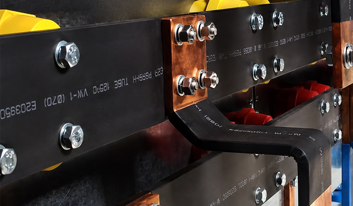
A conical spring washer to DIN 6796, commonly called a Belleville washer, stores elastic energy. As the bar expands, the washer compresses and limits the rise in bolt tension; as it cools, the washer returns and keeps the joint tight. CDA specifies them where steel bolts would otherwise be pushed past safe stress. A Belleville stack changes the busbar joint torque specification, so never carry a flat-washer figure across to a spring-washer joint.
Copper vs. aluminum busbar
Aluminium creeps under sustained pressure at ordinary temperatures; copper needs about 150 °C to creep at a comparable rate. Aluminium oxide forms within microseconds and insulates, while copper oxide forms slowly and still conducts when compressed between copper faces.
Published sources disagree sharply. One widely reproduced table says copper torque may be raised to 150–200% of its tabulated figure. Search M12 bolt torque for copper busbar and you will find 18 Nm to 54 Nm.
The direction holds even where magnitudes do not: copper tolerates more clamping pressure. When choosing copper or aluminum, take any aluminum busbar bolt torque from the connector manufacturer.
Lubrication, plating, and joint compound
Every figure in the table above assumes dry threads. CDA’s nut factor is 0.20–0.22 dry, 0.19–0.21 with contact aid compound, and 0.15–0.16 with a boundary lubricant. Applying a dry-thread torque to lubricated threads produces substantially more clamp force than intended, and field reports describe threads stripping for exactly this reason.
Joint compound is separate from thread lubricant. CDA recommends an oxide-inhibiting contact aid on the mating faces to fill voids and prevent corrosion. It advises against plating copper-to-copper faces unless the environment demands it, because soft plating can flow and relax contact pressure.
If this topic is completely new to you, this beginner-friendly guide is a good place to start.
How to Torque a Busbar Connection Correctly
Answering how tight should busbar bolts be is only half the job. The sequence around the torque wrench decides whether the value you set is the value the joint gets. The same procedure covers a torque value for busbar lugs and terminations.
Good joint preparation starts long before the wrench comes out. A hole punched with worn tooling leaves a raised burr on the exit face, and that burr holds the two bars apart exactly where they should be in contact. The bolt then loads a high spot instead of the joint area. This is where busbar fabrication practice meets maintenance practice. A correct torque figure applied to a badly prepared joint will not deliver the contact pressure it should.
- Confirm the specification. Find the bolt grade, size and the OEM or connector torque value if one exists. Any recommended torque for busbar connections printed by the manufacturer outranks a published chart, including the one above.
- Inspect and clean both faces. Remove oxide, burrs and punching debris. CDA notes that current crosses at discrete contact spots covering roughly 1% of the overlap area. A flat, lightly roughened face changes joint resistance materially.
- Check the washer stack and orientation. Confirm whether the specified torque assumes flat washers or a Belleville, and fit them the right way round. A reversed conical washer provides almost no spring.
- Apply joint compound where specified. Standard practice on aluminium joints. Keep it off the threads unless the figure is a lubricated one.
- Hand-tighten and align. Bring the bars into position and take up the slack before any torque is applied.
- Torque with a calibrated wrench, in sequence. Work multi-bolt joints in rotation rather than one at a time, building up gradually. Torque wrench calibration is not optional on a safety-related bolted joint.
- Mark the bolt head. A witness mark across bolt, nut and bar shows at a glance whether anything has moved since installation.
Step six carries the most field error. A wrench that has been dropped, left loaded at full scale, or simply used for years without recalibration can read several percent off, and the error is invisible. Calibration records matter as much on a busbar joint as the figure itself.
If any part of this feels unclear, this simple explanation describes it in simple language.
Standards and Real-World OEM Examples
No single standard sets one busbar bolt tightening torque for every joint. There is no IEC 61439 busbar bolt torque requirement as such: that standard governs design and verification of low-voltage assemblies. In North America, NEMA CC1 and ANSI C119.0 cover connector and bus-connection fastening. All three set a framework rather than a figure.
Two published examples show how far the actual switchgear busbar bolt torque can sit from a generic chart.
ABB’s Uniswitch installation manual covers busbar connections in 12 kV and 17.5 kV cubicles. It specifies an M10 × 20 bolt, a 10.5 washer and an M10 nut, tightened to 10 Nm. Set that M10 busbar bolt torque against CDA’s 28 Nm and a generic 8.8 figure near 45–57 Nm. The gap is driven by the specific joint, washer and hardware ABB tested.
Schneider Electric’s support documentation gives a busbar terminal torque of 16–18 Nm for the terminal-to-vertical-busbar bolt on Masterpact NW/MTZ assemblies. For any torque spec for busbar to breaker connection, it directs installers to the value printed on the back of the device rather than to a catalogue figure. That instruction is itself worth noting: the manufacturer treats its own published number as provisional.
The instructive detail sits inside ABB’s own documentation rather than between the two brands. The Uniswitch material specifies 40 Nm for an M10 earth connection. One bolt size, one manufacturer, two joints, four times the torque.
That single comparison is the argument against generic charts, made better than any caveat could make it. The number is a property of the joint — its bars, washers, hardware and tested duty — not of the thread. Which joint you are working on matters more than which bolt is in your hand, and the same logic applies when comparing any busbar scheme across manufacturers.
What Happens When Torque Is Wrong
Busbar connection torque values fail in two directions, and the two paths look nothing alike.
Under-torque starts quietly. Contact pressure sits below the level where oxide films break down, so joint resistance is higher than designed. Under load, I²R losses at the interface generate heat. Heat accelerates oxidation, oxidation raises resistance further, and higher resistance makes more heat. That feedback loop is thermal runaway, and it is self-reinforcing: nothing about it self-corrects. Fretting and stress relaxation loosen the joint further as it cycles. CDA notes that no deterioration is noticeable until the final stages of connector life. That is exactly why loose joints are found by thermography rather than by inspection.
Over-torque fails immediately or on the first hot cycle. The bolt yields, threads strip, or a washer’s bearing surface digs into the bar. On aluminium, the conductor itself can cold-flow. Punched holes near a bar edge can distort, and a brittle insulator standoff carrying the reaction load can crack. None of these is recoverable by retightening — a yielded bolt has already lost the clamp force the joint was designed around.
There is a practical asymmetry here worth holding onto. Over-torque announces itself, usually during assembly, and usually to the person who caused it. Under-torque does not announce itself at all. It passes commissioning, passes visual inspection, and degrades quietly for months or years before the first thermal signature appears. That is why the under-torque path deserves more attention than it usually gets, and why the maintenance regime in the next section exists.
Checking and Re-Torquing Busbar Connections Over Time
Bolted joints move over their service life. Thermal cycling, copper creep and vibration all relax clamp force gradually, so a joint torqued correctly at commissioning is not guaranteed to stay that way. Nothing about a bolted electrical joint is permanent, and the maintenance regime exists because of that.
Practice has shifted on how to respond. Traditional maintenance called for scheduled annual re-torquing of every connection. Current thinking increasingly favours thermographic inspection, with repairs triggered by findings. Indiscriminate re-torquing disturbs sound joints, and field data suggests only a minority of loose connections improve from re-torquing alone. Most need full disassembly, cleaning and reassembly.
Thermal imaging is the non-invasive first check. Compare joint temperature against nearby bar under similar load; a widening differential is an early warning. The comparison matters more than the absolute reading, because load and ambient both vary between surveys.
Witness marks make the follow-up faster, showing at a glance which fastener has moved. Record the load at the time of each survey, so the next reading can be compared meaningfully rather than guessed at. A short log beats a good memory once the panel has been in service for a decade.
Flexible connections are worth checking on the same rounds, since busbar connections that absorb movement carry their own inspection needs.
Conclusion about Busbar Bolt Tightening Torque
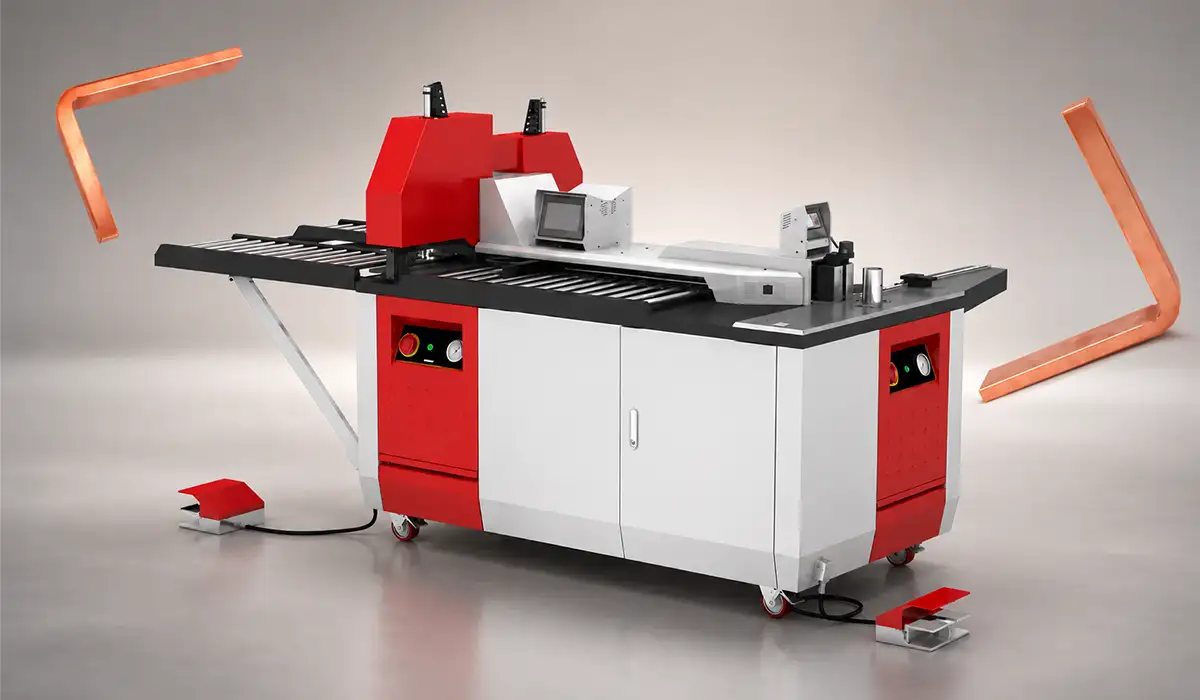
Use the M6–M16 table as a sanity check, not as an instruction. Before committing a real joint, confirm three things about the busbar bolt tightening torque you plan to apply. The manufacturer’s documented value. The actual bolt grade and material in your hand. The washer stack the figure assumes. Where any of those disagree with a published chart, the manufacturer’s figure wins every time. PAYAPRESS builds the punching, cutting and bending machines that prepare busbar for these joints, and joint quality starts with a clean, accurately punched hole.



Rate this article
Choose a rating from 1 to 5 stars.
No ratings yet