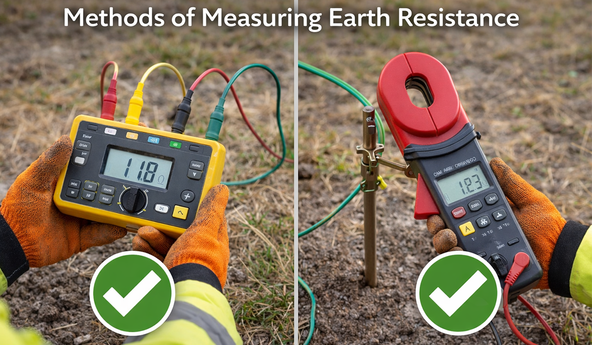


Earth resistance measurement is essential for verifying the safety and performance of grounding systems. The main methods of measuring earth resistance include the fall-of-potential method, the 62% rule, the slope method, the three-point method, and other field techniques used when standard testing conditions are difficult.
Before choosing a test method, it is important to understand the difference between soil resistivity and earth electrode resistance. Soil resistivity describes how strongly the soil resists electrical current, while earth electrode resistance measures how effectively an installed grounding electrode dissipates current into the surrounding earth.
Soil Resistivity
Soil resistivity is the electrical resistance of soil expressed in ohm-meters (Ω·m). It indicates how easily current can flow through the ground and is normally measured before designing or installing a grounding system.
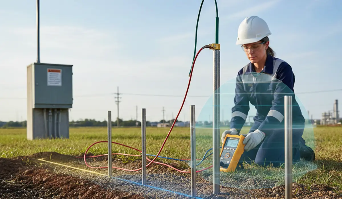
Soil resistivity is the resistance of one cubic meter of earth measured between two plate electrodes. The soil’s resistivity depends on the materials that make up the earth, so it varies from place to place. To measure soil resistivity, four electrodes are used (all four are temporary). Four auxiliary electrodes are driven into the ground at a shallow depth, about one meter, with equal spacing and in a straight line.
If the information related to topic X was interesting and informative to you, researching topic IP55 vs NEMA 12 can be very engaging.
Earth Electrode Resistance
Earth electrode resistance is the resistance of the mass of soil around the electrode out to infinity. It is important to note that this resistance is not equal to the resistance of the electrode itself, as the metal electrode has very low resistance.
To gain a deeper understanding of Topic Electrical resistance survey, we highly encourage you to consult this insightful piece.
The Role of Soil in Earth Electrode Resistance
The further we move from the electrode, the smaller the influence of the surrounding soil becomes, which is why paying attention to the soil around the electrode is fundamental to reducing earth electrode resistance.
Steps for Measuring Earth Resistance
- Disconnecting the main power source
- Ensuring the power is disconnected and cannot be reconnected by others
- Using personal protective equipment (PPE)
Factors that Reduce Earth Electrode Resistance
- Increasing the length of the vertical electrode
- Using multiple parallel electrodes
- Improving soil resistance using electrolytes
Effect of Increasing the Length of a Vertical Electrode
The more one dimension of the electrode is larger than its other two dimensions, and the more the electrode’s contact with soil is along that dimension, the smaller the total electrode resistance relative to the mass of earth becomes.
Effect of Using Multiple Parallel Electrodes
Using multiple electrodes in parallel reduces earth resistance by a certain percentage. For example, Using multiple electrodes in parallel can reduce total earth resistance, but the reduction is not linear. The final resistance depends on electrode spacing, soil resistivity, electrode depth, and the interaction between resistance areas around each electrode.
Soil Resistance and Its Impact
Soil electrical conductivity is influenced by several physical and chemical factors that affect the movement of electric current through the soil. Among the most important of these factors are soil salinity, moisture content, and temperature, each of which plays a significant role in determining conductivity levels.
Soil Salts
The electrical conductivity of soil depends on the amount of conductive salts present in the soil. The higher the concentration of salts, the lower the resistivity and the higher the electrical conductivity.
Soil Moisture
Soil moisture plays a key role in electrical conduction. Electrical conductivity increases with moisture, but when moisture becomes excessive, conductivity decreases.
Soil Temperature
Conductivity increases with temperature. For example, for every degree Celsius above zero, conductivity increases by about 2%.
Measuring Earth Electrode Resistance
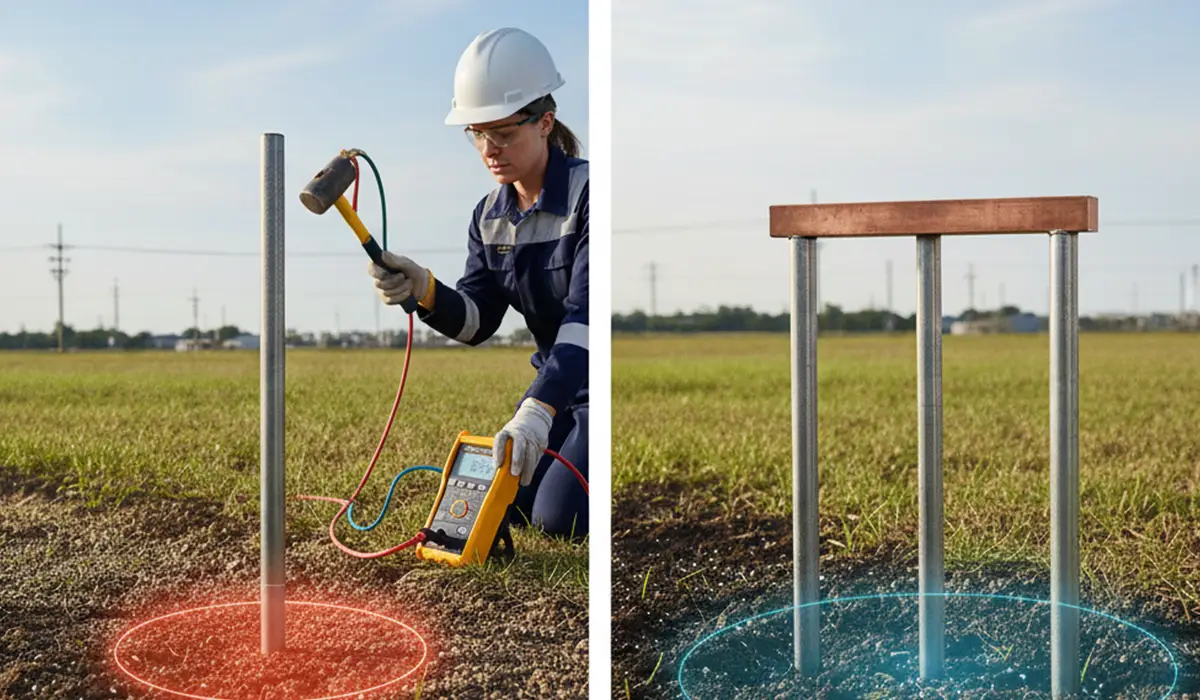
The basis for measuring earth electrode resistance is using a current source to pass current through the electrode, measuring the voltage, and then dividing the voltage by the current to calculate the resistance.
If the details you gathered about topic Measuring Earth Electrode Resistance were interesting and insightful, you may find diving deeper into topic IEC, UL, and CE Standards equally captivating.
Fall-of-Potential Method
The fall-of-potential method is the most common and valid method for measuring earth resistance. It uses a current source and measures the voltage between the auxiliary potential rod and the electrode.
Measuring Earth Resistance Using the 62% Rule
The 62% rule simplifies the fall-of-potential method by measuring the voltage at 62% of the distance between the auxiliary current electrode and the earth electrode. While faster, this method requires an error test for confirmation.
Your deep dive into Topic Measuring Earth Resistance isn’t complete without the essential insights found in this article
Other Methods for Measuring Earth Resistance
- Dead Earth Method (Two-Electrode Method)
- Current Injection Method
- Connected-Rod Method (ART)
- Star-Delta Method
If the material related to topic Methods for Measuring Earth Resistance was both useful and intriguing to you, diving into topic Types of Electrical Wires and Cables will likely be equally fascinating.
Practical Notes for Fall-of-Potential Measurements
- The current and voltage rods must be firmly driven into the ground.
- The entire length of the wires must be fully uncoiled.
- The measurement distance must be large enough to avoid interference from nearby resistive zones.
Measuring Earth Resistance Using the Slope Method
The slope method is used when the fall-of-potential method has errors greater than 5% or when the required measurement distance is too large.
If you are looking for more information about topic Slope Method, it is recommended not to miss reading this article.
Measuring Earth Resistance Using the Three-Point Method
The three-point method is used when it is not possible to drive rods in one straight line, but rods can be driven in different directions at distances greater than 5D from the electrode.
Measuring Earth Resistance Using the Similar Grounding Connection Method
This method is used when two similar grounding connections exist on site. The resistance is measured, and the value is approximated by dividing the combined resistance by two.
Conclusion
Proper measurement of earth resistance is essential for the safety and proper functioning of grounding systems. By using the correct method and accounting for soil properties and electrode conditions, accurate measurements ensure reliable and safe electrical systems.